ODM OTR 700 OTDRs User manual

Revision D
04/2016
OTR 700
Optical Time Domain Reectometer
User's Guide
Copyright 2016
Information contained in this manual is believed to be accurate and reliable, however, no responsibility is
assumed by ODM Inc. for its use nor for any infringements of patents or other rights of third parties that may
result from its use. No license is granted by implication or otherwise under any patent rights of ODM Inc..
The information contained in the publication is subject to change without notice.
This guide is written for use with the OTR 700 series.
This includes the standard OTR 700 OTDRs, OTR 700-EXT, OTR 700-PON and OTR 700-CWDM
Optical Design Manufacturing Inc.

I
1. Using This Manual.….....…………................................……....................................................….…………………1
2. Safety...................…...................................................…….………..............................…………………...…………2
3. OTR 700 Quick Start Guide.................................................................................................……......……..………4
4. Introduction ………….........……................................................................................................…….……...……..6
5. OTDRInspectionandIdentication.....................................................................................………………...……7
5.1 Inspection
5.2 IdenticationandConguration
6. OTR 700 Depscription…….……….........................................................................................…….......……….8
6.1 OTDR Physical Description
Instrument Enclosure
Front View
Top View
6.2 Home Screen Display
6.3 Power Requirements
6.4 Battery Replacement
4 NiMH Batteries
Li-ion Pack
7. Fault Locator...........................................................……........................................................................................11
7.1 Fault Locator Operation
Set Wavelength
Start Scan
Exit Fault Locator Mode
7.2 Fault Locator Screen
Event Table
Schematic View
EventTableFieldDenitions
8. OTDR Operations............................................……..............................................................................................15
8.1 Key Pad
8.2 Entering OTDR Function
8.3 IconDenitions
8.4 Main OTDR screen
8.5 OTDR Parameter Settings Screen
Trace Parameters
Event Table/Schematic View Sensitivity Settings
Pass/Fail Thresholds Settings
Date/Time Settings
Exit Parameter Settings Screen
Chapter PAGE

PAGE
II
(Continued)
Chapter Table of Contents
8.6 Auto Test
Set IOR
Set Wavelength
Start Auto Test
8.7 Manual Expert Mode
Set IOR
Set Wavelength
Set Range
Set Pulse Width
Set Averaging Time
Scan
8.8 Construction Mode
Create or Open a Project
Set Base File Name
Set Wavelenghts
Start Testing
Exit Construction Mode
8.9 Trace Analysis
Unit of Measure
Zoom
Cursor Movement
8.10 Loss Measurements
2 Point Loss
dB/km
Optical Return Loss
Basic Splice Loss
Least Square Approximation (LSA)
8.11 Loss Measurement Settings
Setting Splice Loss Measurement Areas
Splice Loss Measurement Areas
Splice Loss Adjustment Positions
LSA Examples
8.12 Event Analysis
Enter Event Analysis
Threshold Settings
Sensitivity Settings
Macrobend Analysis
Event Analysis Screen
Schematic View
Event Table
Event Table Field Descriptions

PAGE
Table of Contents
Chapter
III
(Continued)
9. Project Management............................................................................................................................................33
9.1 Project Management Description
Project Management Screen
Project Management Menu
Project Management File Tab
Project Management Edit Tab
Project Management View/Help Tabs
9.2 Project Management Operation
Create a New Project
Open an Existing Project
Delete a Project
Upload a Project to OpTrace
Rename a Project
Modify Properties
TemporaryModicationofParameters
Exit Project Management
10. File Management..................................................................................................................................................37
10.1 File Management Description
File Management Screen
File Management Menu
File Management File Tab
File Management Edit Tab
File Management View/Help Tabs
10.2 File Management Operation
Saving a Trace
Open/View a Trace
Dual Trace Mode
Delete a File
Upload a Trace to OpTrace
Rename a Trace File
Exit File Management
11. Video Scope........................…..................................................................….................................…...................40
11.1 Entering Video Scope Function
11.2 Video Scope Display
11.3 Video Scope File/Help Icon Menu
Home
Quick Save
Project Management
File Management
Help
11.4 Video Scope Operations Icon Menu
Grading Rings
Pass/Fail Label
Brightness

11.5 Video Scope Operation
Video Probe Tips
Viewing/Focusing a Connector
Centering a Connector Image
Pausing Image Scan
Grading Rings
Pass/Fail
Marking Points of Contamination
Exiting Video Scope Operation
11.6 Pass/Fail Criteria Tables
Fiber End Face Criteria Table for Angled PC Polished Connectors
Fiber End Face Criteria Table for Ultra PC Polished Connectors
Fiber End Face Criteria Table for PC Polished Connectors
12. Loss Test Set.......................................…...................................................…..................................…..............
....45 12.1 Entering Loss Test Set Function
12.2 LTS File/Help Icon Menu
Home
Quick Save
Project Management
File Management
Help
12.3 Light Source Operation
Selecting Light Source Wavelength
Selecting Source Modulation
12.4 Power Meter Operation
Set Power Meter Wavelength
Set Reference
Set Measurement Units
12.5 LTS Project Management
12.6 LTS File Management
12.7 Exit Loss Test Set
12. Specications.........................…...................................................…..............................................…..................47
13.1 OTDRSpecications
13.2 PowerMeterSpecications
13.3 LightSourceSpecications
13. Repair/Warranty.......................................................................................…..................................…...................48
14.1 Repair Information
14.2 Warranty Information
15. Version Control........................….........................................................................................................................49
PAGE
Table of Contents
Chapter (Continued)
IV

1
OTR 700 User's Guide Rev02 11/2016
Warning
A warning alerts to situations that could cause personal injury.
Caution
A caution alerts to situations that may cause damage to the equipment or produce poor testing condi-
tions resulting in inaccurate test results.
Note
A special annotation that will assist the user with operational features.
Chapter 1 Using This Manual
There are warnings, cautions and notes posted throughout this manual.
Opticaltimedomainreectometersareopticalinstrumentsthatemitlaserradiationandthoughthislevelof
radiation is not considered a danger, there are safety considerations and certain practices that should be
followed.
Please read and follow all warning and caution information noted in this manual.
Precautions
There are also a few touch screen tips scattered through this manual, these will assist the user with
touch screen operation. They will be preceeded by the green text below:
Touch Screen Tip
ThismanualcontainsoperationinformationfortheODMInc.,OTR700OpticalTimeDomainReectometer.
This OTDR may be operated by using the touch scree or the onboard key pad. The touch screen is a resistive
style screen and only proper stylus devices should be used when using the touch screen capability.
This guide is written to instruct operation via the onboard keypad. There will be tips throughout the manual to
assist with touch screen operation.

OTR 700 User's Guide Rev02 11/2016
2
This product has been designed and tested in accordance with the manufacturer’s safety standards, and has
been supplied in a safe condition.
This document contains information that must be followed by the user to ensure safe operation and to maintain
the product in a safe condition. Failure to follow these safety warnings and cautions can result in harm to the
user or damage to the instrument.
Warning
Personnel should always be aware when working with fiber optic test equipment that active fibers may
be present, therefore infrared optical energy may be present.
Warning
Never look directly into the end of a connected fiber optic cable or fiber optic interface of optical test
equipment, to do so could expose the user to laser radiation and could result in personal injury.
Warning
To Prevent Fire or Shock Hazard:
Chapter 3 of this manual is a quick start guide. Prior to using the quick start guide or operat-
ing the equipment in any way, it is highly suggested the user reads all safety information.
Chapter 2 Safety
The information in this chapter pertains to safety consideration of OTDRs in general.
Do not install battery types other than those supplied by the manufacturer
Do not use the charger without the proper batteries installed
Do not expose the battery charger to rain or excessive moisture
Do not use the AC adapter when there are signs of damage to the enclosure or cord
Ensure that you are using the correct charger for the local line voltage
Do not use any other charger than the one provided with this instrument.
Do not puncture batteries.
Do not incinerate batteries.
All batteries should be disposed of in a proper manner.
Failure to follow these caution statements could cause unsafe conditions for the operator and
equipment and may void the warranty.

3
OTR 700 User's Guide Rev02 11/2016
Failure to follow these cautions statements may void the warranty of, or cause damage
to this equipment.
Caution
Fiber-optic connectors are easily contaminated or damaged. The connection to the OTDR is physical
contact type of connections and dirty or damaged connectors may impair the instruments capabilities at
minimum and at worst result in the need to return the OTDR to the factory for expensive repairs. Prior
to making any connection to the unit, ensure that all proper cleaning procedures have been followed.
Use UPC Finish Connectors Only -- DO NOT insert APC connectors into the optical ports.
Caution
The OTDR is equipped with a protection circuit to avoid damage from live fiber connections, the in-
strument will not operate properly with active fibers. Even with this protection, high power output from
EDFA’s or other equipment can damage detectors and should never be connected to the OTDR.
If a live fiber is connected to the OTDR and a scan is attempted, a warning dialog will be displayed as in
fig. 2.1. Immediately remove the live fiber from the OTDR and press select to clear the message.
Chapter 2 Safety
Fig 2.1

OTR 700 User's Guide Rev02 11/2016
4
Chapter 3 Quick Start Guide
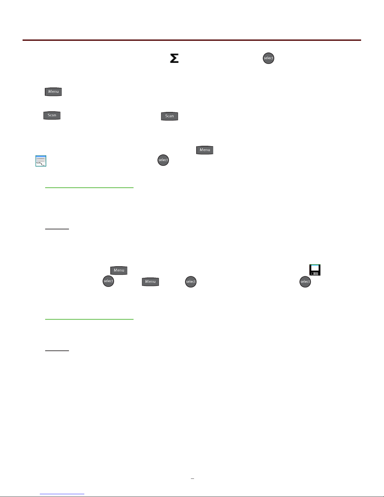
Press to turn on the OTDR.
Use the directional buttons to highlight the OTDR icon and press to enter the OTDR function.
Connectthebertotheappropriateport.(SMorMMOTDROpticalPort)
Press to enter the Menu mode. The menu is displayed at the top of the screen. (To hide the
menu, press the menu button a second time.)
Use the right button to highlight the (wavelength) icon and use to cycle to the desired wave-
length.
If approximate ber length is unknown:
Press to have the OTDR start a test using the selected wavelength, allowing the OTDR to de-
termine the most appropriate range and pulse width. (Autotest will set the averaging time to 60sec.)
If approximate ber length is known:
Set the Wavelength as above and further set the range, pulse width and averaging time.
Press to open the icon menu, use the left or right arrow to highlight the (range) and use
to cycle through the available ranges of 250m, 1km, 4km, 16km, 64km, 128km or 256km.
Use the left or right buttons to highlight the (pulse width) icon and use to cycle through the
available pulse widths of 5ns, 10ns, 30ns, 100ns, 300ns, 1us, 3us, 10us or 20us. (Not all pulse
widths will be available, only pulse widths appropriate for the selected range will be presented )
Prior to using this quick start guide or operating the equipment in any way, it is highly sug-
gested the user reads all safety information in chapter 2.

5
OTR 700 User's Guide Rev02 11/2016
Press the left or right button to highlight the (average) icon and use to cycle to the averaging
times of Real-Time, 15 seconds, 1, 4, 16 or 40 minutes.
Press to exit the menu mode and hide the menu bar.
Press to start a trace. Pressing the again will stop a trace. To operate the cursors, use the
left and right buttons. Press the A/B button to toggle between A and B as the active cursor.
To view the Schematic View and event table, press , use the left and right buttons to highlight
the (schematic view) icon and press .
Touch Screen Tip
Alternately, the touch screen may be used to select the event table or the Schematic view by touching
the tabs immediately below the grid scale.
Note
The OTDR tab displays the trace with the parameters listed and loss and distance measurements dis-
played. The Event tab displays the trace with numbered events and an interactive event table, while the
Schematic tab displays the trace with numbered events and the interactive schematic view of the data.
Tosaveatrace,pressthebuttonandusetheleftorrightbuttonstohighlightthe(le
storage) icon and press . Press , press and with save highlight press . Use the
touchscreenkeyboardtoenterthelenameandtouchsave.
Touch Screen Tip
The onboard QWERTY keyboard is only operational with the touch screen capability.
Note
The Quick Save icon may also be use to save the trace. Touching the Quick Save icon will store the
tracetotheactiveprojectfolderandusethelastbaselenameentered.
Chapter 3 Quick Start Guide

OTR 700 User's Guide Rev02 11/2016
6
Dear Valued Customer,
ThankyouforchoosingODMInc.foryourberoptictestingrequirements.Our
professional staff is available to answer any questions or provide assistance that you
require. We, at ODM, strive to provide premier customer care and technical support
by providing timely responsiveness and training. We are proud of our quality and high
standardsandassureyou,themostuserfriendlyandaffordableberopticsolutionsto
meet individual needs.
Chapter 4 Introduction

7
OTR 700 User's Guide Rev02 11/2016
Before shipment, this instrument was inspected and found to be in perfect working order and free of
defects.
The shipping carton contains the following:
1. OTDR with Protective boot
2. Universal AC/DC charger with interchangeable mains
3. USB cable
4. Manual
5. Set of interchangeable OTDR adapters, SC, ST and FC and Power Meter adapters for SC,
ST, FC, 1.25 universal and 2.5 universal.
Note
ST OTDR adapters are not supplied with PON or CWDM OTDRs)
Fig 5.1
Chapter 5 Inspection and Identication
5.1 Inspection
The instrument’s Model/Part Number, Serial Number and Date of Manufacture are indicated on a
labellocatedonthebackoftheunit.Theinstrument’shistoryisledatthefactorybymodel/part
number and serial number. The unit's serial number is also located on the top plate just above the
USB Port.
5.2 Identication and Conguration

OTR 700 User's Guide Rev02 11/2016
8
Chapter 6 OTR 700 Description
6.1 OTDR Physical Description
Instrument Enclosure
The ODM OTR 700 is packaged in a rugged housing which is further protected with a rubberized
boot. Although the front panel is weather resistant, care must be taken to avoid liquids and contami-
nants around the fragile optical and electrical connectors, and the glass display. Use a mild cleaning
agent and soft damp cloth to clean up the panels and the outside case. See the maintenance sec-
tion to clean the optical connector. NEVER open the instrument for cleaning. Return to the factory for
servicing if necessary.
Front Panel
Power Button
Key Pad
Color Touch Screen
Fig 6.1
Protective Rubber Boot
Top panel
OTDR Port
Power Jack
Position of Second
Optical Port for Quad
Wavelength OTDRs
Video Probe Port
USB Port
Unit Serial Number
Fig 6.2
Battery Charge
Indicator

9
OTR 700 User's Guide Rev02 11/2016
This unit is equipped with a 4” color TFT resistive touch display. Keyboard functions are also executable on the
touch screen.
Chapter 6 OTR 700 Description
6.2 Home Screen Display
Fig 6.3
Touch Screen Tip
These icons may be selected with the touch screen function.
6.3 Power Requirements
The OTR 700 is equipped with either 4-AA NiMH Batteries or with a 2600mAh Li-ion battery.
The 4 NiMH batteries require a 100-240V-0.3A input and 9V, 0.67A center positive output universal AC/DC
battery charger. A fully charged NiMH batter pack will enable about 4 hrs. of use and require 6-8 hours to
recharge.
The Li-ion batteries require a 100-240V-0.6A input and 15V, 1.2A center positive output universal AC/DC
battery charger. A fully charged Li-ion battery pack will typically enable approximately 9 hrs. of use and require
approximately 2 hours of recharging.
The appropriate charger is supplied with each OTDR and it is clearly labeled above the charge port on the
OTDR, which charger is required. These chargers are supplied with interchangeable mains for US, Great
Britain, Europe and Australia.
Visual Fault Locator
If unit is equipment with a VFL,
selecting this icon with will cycle
through CW, Modulate and Off.
Loss Test Set
If CW source is available, Select
this icon to access the CW mode of
the light source.
Video Scope Icon
Select this icon to open the video
scope function.
Optical Time Domain Icon
Select this icon to open the
OTDR function
Firmware Version

OTR 700 User's Guide Rev02 11/2016
10
Warning
To Prevent Fire or Shock Hazard:
Do not install battery types other than those supplied by the manufacturer
Do not use the charger without the proper batteries installed
Do not expose the battery charger to rain or excessive moisture
Do not use the AC adapter when there are signs of damage to the enclosure or cord
Ensure that you are using the correct charger for the local line voltage
Do not use any other charger than the one provided with this instrument.
Do not puncture batteries.
Do not incinerate batteries.
All batteries should be disposed of in a proper manner.
Failure to follow these caution statements could cause unsafe conditions for the operator and
equipment and may void the warranty.
Chapter 6 OTR 700 Description
6.4 Battery Replacement
4 AA NiMH
To replace the batteries, remove the OTDR from the protective boot by pulling the bottom of the boot down
and back allowing the bottom of the unit to be lifted out. The battery door is located on the back side of the
unit. Replace the batteries with only high quality AA NiMH batteries. Spare battery packs are available with
a charging unit for extended battery operation. If you install NiMH batteries that are dead or less than 1 volt
each, charge these batteries for one (1) hour before using the OTDR. For proper maintenance, batteries require
a monthly recharge.
Li-ion Pack
Thebatteriesnoteldreplaceable.AnRMAshouldbeacquiredandtheunitmustbereturnedtothe
factory for battery replacement. This Li-ion battery pack should not be punctured, incinerated or disposed of
improperly.

11
OTR 700 User's Guide Rev02 11/2016
Chapter 7 Fault Locator Operation
7.0 Fault Locator
The Fault Locator is a simple autotest feature which displays the test results in event table with the schematic
view.Thefaultlocatorwilltakeascanoftheberinautotestmode.Theusersetsthewavelengthtobe
testedandtheOTDRwillsetthepulsewidthandrangetobestsuitetheberundertestattheselected
wavelength. The average time will be set to 15 seconds.
7.1 Fault Locator Operation
To enter the Fault Locator mode, touch the FAULT icon on the home screen. The screen below will be
displayed.
Touch Here To
Select
Wavelength
Touch The Lower Area
Of The Screen To
start a Scan
Set Wavelength
To select the wavelength to be tested, touch the wavelength indicator as shown in Fig. 7.1 above, t his will cycle
through the available wavelengths on the OTDR.
Start Scan
To start a scan, touch in the bottom right corner of the display. A "Please Wait, Scanning" message will be
displayed. The scan will take about 15 seconds.
Exit Fault Locator Mode
To exit the fault locator mode double touch in the event table area or press the Menu button.
Fig 7.1
Double Touch in the
Table Area to return
to the Home Screen

OTR 700 User's Guide Rev02 11/2016
12
Chapter 7 Fault Locate Operation
7.2 Fault Locator Screen
The fault locator screen includes the event table, Schematic View and event map view of highlighted event.
Fig 7.2
7.1 Fault Locator Operation Continued
When a scan it taken with the Fault Locate, the trace information is temporarily stored in the OTDR. If the full
trace needs to be viewed, double touch in the event table area or press the Menu button to return to the home
screen. Touch the OTDR icon and the trace will be displayed with full OTDR operation.
Schematic
View
Event Table
Event Map
with adjustable
splice zones
Trace Param-
eters

13
OTR 700 User's Guide Rev02 11/2016
Chapter 7 Fault Locate Operation
Fig 7.3
Failing Event is Red
Event Number
Schematic View
Range of the Trace
Red Ares is
Currently Being
Displayed
Event Table
Event Number
Pass/Fail
Event Location Event Loss in
dB
Loss Between
Previous and
Current Events
dB Per/Km, Kf or Mi
Between Events
Event Type or
Reectance
Value
Fig 7.4
Reective
Events
Event Location
Note
The End of Fiber is the last item in the schematic view. It is labeled E in the event number position and
displays a vertical Bar instead of horizontal.
Link Informa-
tion Link Loss
EOF Event
Information
System ORL
Fiber Link Length
Passing event
is green
Non-Reective
Event
Link dB Per/
Km, Kf or Mi

OTR 700 User's Guide Rev02 11/2016
14
Event Table Field Description
# Event Number:
Indicates the event in sequence, where the higher the number the further distance from the OTDR the event
occurs.“E”(End)whichistheeventdeterminedtobetheendoftheberundertest.Thelastcolumnis
labeled"L"therowincludeddatathatisrelevanttothelink(fullberundertest).
P:
Pass/Fail, if any one of the thresholds are not met for and event, the P/F column will display an F. The
parameter that failed will be displayed in red. If all the parameters are met, this column will display a P. There
is no Pass/Fail threshold for the last event labeled "E" (End) and the Pass/Fail for the "L" (Link) row includes
the 2POINT column, which for the link is the total link loss and the TYPE column which for the link row is the
system ORL.
Km or KF or MI:
Event Location (Distance from OTDR), Labeled Km for Kilometer or KF if unit of measure is Kilo-feet MI for
mile.Thisisthedistance/locationthattheeventoccursalongtheberlink.Thisdatashouldbethesamefor
the End of Fiber and Link.
Splice:
SPLICEisthedBlossattheeventatthislocationontheber.Lossisrepresentedasapositivenumber.(A
positive number is the amount of loss and a negative number indicates a gain normally due to mismatched
index of refraction.) This is a settable threshold for the Pass/Fail purposes. The "E" event will display LINK as
this is not an event that would have meaning. The event that is deemed the EOF will normally display a large
lossasthislosswillbegreaterthanthethresholdsettodeterminetheendoftheber.
2PO I NT:
2 Point Loss is the loss measured from the end of the dead zone of the previous event to the beginning of
current event. The value in the "L" line of the table for this column is the link loss. The loss from the beginning
ofthetracetotheeventdeterminedtobetheEOF.Thisisthevalueusedtodetermineiftheberlinkpasses
or fails it's loss threshold.
dB/Km:
dB per Kilometer if in KM and DB/KF if in Kilo-Feet and DB/MI if in mile unit of measure. This is the
calculated loss per Km, Kf or Mi from the end of the dead zone of the previous event to the beginning of the
current event. The value in the "L" line of the table for this column is the dB Per/KM, Kf or Mi for the total link.
TYPE:
EventTypeisthetypeofeventorthereturnlossofandevent.Iftheeventhasnoreection,“splc”willbe
displayedandiftheeventisreective,thereectancevaluewillbedisplayed.Forthelasteventwhichis
labeled "E", there is not value displayed, it simply shows "End" and in the "L" row, the Optical Return Loss for
the link is displayed (System ORL).
Chapter 7 Fault Locate Operation

15
OTR 700 User's Guide Rev02 11/2016
Chapter 8 OTDR Operation
8.1 Key Pad
Power button, turns the unit On and Off. (Hold for 1 second)
Scan button starts a scan or stops scan.
AutoTestbuttonoperatesrangendermodeandconstructionmodes.
The Menu button displays and hides the icon menu at the top of the display. It will also back out of most menu
selectedscreens.Intheprojectfolderandlemanageritopensthele/editmenubar.Whenthemenuis
displayed at the top of the screen, the focus of the LRUD buttons and the select buttons are on the icon menu
and no longer on the trace cursors.
Toggles between A and B as the active cursors.
Selects the Zoom level, each press cycles to the next zoom level. Zoom levels are 1x, 2x, 4x, 8x, 16x and 32x.
In the menu mode, the select button actuates highlighted item.
While in the trace mode the directional buttons are used to move the cursors. In the Menu mode, the Left and
right buttons move between the icons. The up button hides the menu bar or moves cursor up in drop-down
menus and the down button opens, drop-down menus or move cursor down while in a drop-down menu.
Fig 8.1
This manual suits for next models
3
Table of contents
Other ODM Measuring Instrument manuals