6
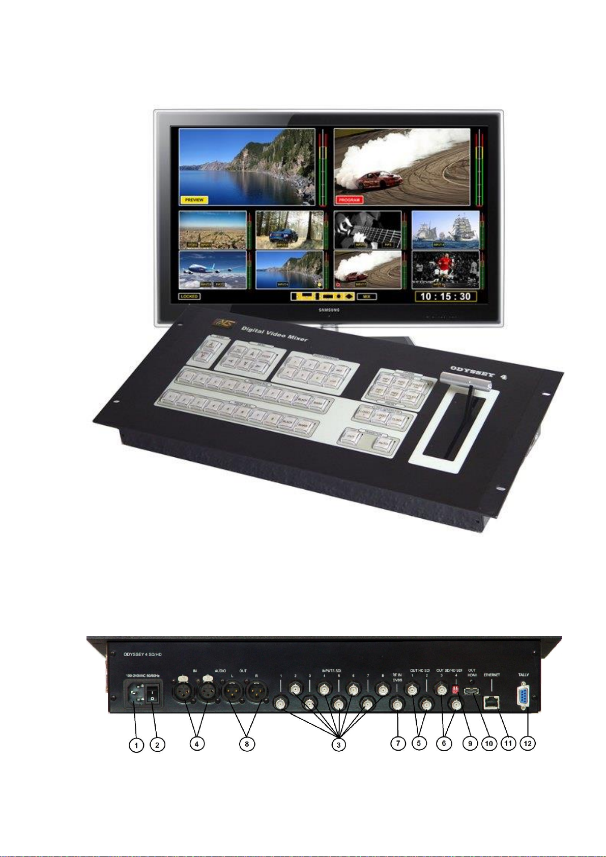
1.2. Destination of connectors (Fig. 1)
1 POWER 220V 220Vpowersupplyconnector
2 I/O powersupplyswitch
3 INPUTSDI SD/HDSDI videoinputs
4 AUDIOIN (L/ R) analogaudioinputs
5 HDSDIOUTPUT HD SDIvideooutputs
6 SD/HDSDIOUTPUT SD/HDSDIvideooutputs
7 RF IN inputofexternalreferencesignal
8 AUDIOOUT analogaudioautputs
9 modeswitcher
10 HDMIOUT multiviewers HDMIpreviewoutput
11 ETHERNET Ethernetconnector
12 TALLY socketfor Tallyinterface
1.3.Connection to a power supply network
Is made through the power supply connector POWER 220V on the rear panel (1 on Fig. 1).
Connection must be made to a socket with a ground contact. Before this, it is necessary to make
sure that the power switch button (2 on Fig. 1) is in O(OFF) position .
1.4. Connection of signal sources
It is possible to connect 8 non-synchronous sources of HD or SD SDI video signals (BNC
connectors - 3on Fig. 1) . On SD mode it is possible to mix between SD and HD video signals.
It is possible to use synchronous sources also. In this case mixer is passes to the slave mode
from a signal of external synchronization through RF IN ( socket 7, fig. 1) from the BBG
(Black Burst Generator, PAL) for SD mode or three-level for HD mode.
As sources of video it is possible to use slides (loaded earlier from external PC static images),
color BARS (4, fig. 2) and black field (BLACK) (3, fig. 2), presented by separate buttons on
mixers buses.
The sources of audio soundtrack signals can be embedded audio in SDI or analogue signals
from an external audiomixer. There is a possibility to assign any of sound channels to any of
video inputs.
Connection of analogue audio sources (two mono or one stereo).) is carrying out through
AUDIO IN (L/R) sockets (two XLR sockets - 4, fig. 1).
1.5.Output connections
There are four video outputs ( HD SDI OUTPUT , SD/HD SDI OUTPUT) ( BNC sockets -5
and 6, Fig. 1). Two of them (5, Fig.1) are use only in HD mode. The rest (6. Fig.1) can be SD or
HD –reassign in menu.
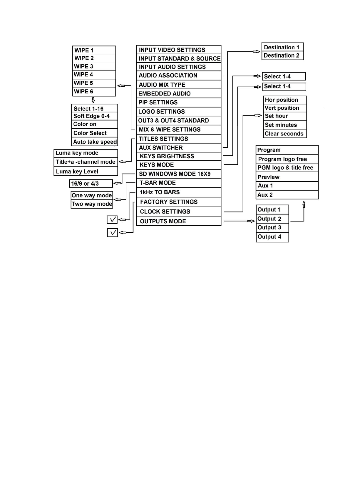
Each of 4 SDI video outputs can be renominated in the menu to output one of 6 signals:
- program output (PGM)
- program output without logos and titles (Titles Free),
- preview output (PVW),
- program output without logos (Logo Free),
- output of internal switcher 1 (Aux1),
- output of internal switcher 2 (Aux2)
The group of embedded audio signals are assign for each of SDI output