avoided as it is not as durable. Allow about 2½ feet (0.8m) of free
cable at the speaker cut-out and sufcient length at the other end
to reach the electronics. Having to add extra cable later can be
tedious and time consuming.
Avoid bundling speaker cables parallel to electrical cables for
extended lengths. Though the impedance is low and the likelihood
of interference low, this may help reduce hum and RF interference.
When securing the cable, use care not to staple or nail through the
electrical conductors. Doing so could result in a short that might
damage the electronics.
When connecting your speakers, make sure proper polarity
(phasing) is maintained. Simply put, this means ensuring the
same wire which is connected to the positive terminal of the
amplier has its other end connected to the positive terminal of
the speaker. It is important to check this on all speakers. If the
connections on one of the speakers are reversed, (out of phase)
the sound quality will be impaired.
If the drywall has not yet been installed a Rough-in-Bracket (RIB-
LCR) may be used to reserve the speaker location on the wall.
The RIB-LCR brackets are available from the distributor or dealer
where the speakers were purchased. When these brackets are
used the holes are cut when the drywall is installed. The cable can
be tied off on the bracket after securing the cable to a nearby joist.
If the drywall is installed and the speaker locations have not yet
been established, then do so now. Assess the wall for possible
concealed obstructions such as wiring, plumbing, etc. Inspect the
backside of the wall, the attic, and/or the crawl space if available
for clues to possible obstructions. Use inspection holes with
inspection tools (camera, mirror, ashlight, etc.) if absolutely
necessary. Use a “stud nder” to locate the positions of the studs.
Once the speaker locations are established
use the cardboard template (the outside
of the inner cardboard rectangle) to mark
the speaker cut-out. The dimensions for
the cut-out are listed in the chart on the
previous page. Using the proper tool, cut
the appropriate sized hole in the wall.
On drywall, clean cuts can be made with
a drywall saw. Cut-out dimensions are
included on the 1st page.
If the cable has not yet been run, do so now
that you have access to the wall’s interior.
To aid in speaker performance, a brous
material, such as berglass, may be
placed behind the speaker. This may
also help to reduce unwanted sound
from being transmitted into adjoining
rooms. If the wall space has blown or
loose insulation, care must be taken
to prevent the loose insulation from
entering the back of the speaker. This
can be accomplished by placing a batt
of berglass insulation behind the back
of the speaker.
Install the frame and clamp ring
assembly by passing the metal clamp
ring through the cut-out as illustrated
in The frame
should t cleanly, without interference,
in the cut-out hole. If the hole is a little
small then trim the hole as needed.
Lightly tighten the screws to secure the
clamp ring against the back of the wall
Use care not to over-tighten
the screws or the frame may become
distorted.
Pull the end of the cable out of the wall,
strip back a section of the jacket as
needed, and then expose ½" (13mm) of
each conductor. Connect the wire to the
terminals on the back of the speaker
assembly, observing polarity (+ & -).
Insert the speaker into the frame and
install the eight screws
The grilles can be painted using multiple light coats of spray paint.
Custom color spray paints are available from specialty companies.
Contact your dealer for more information. The grilles should be
removed from the speaker and painted in a clean environment to
prevent contamination. It is best to go around the grilles and apply
the paint from multiple angles. DO NOT remove the scrim cloth
from the backside of the grille. It is not replaceable.
Attach the grilles to the speakers and enjoy. Should you wish to
remove the grilles from the speakers pull at the grilles' corners.
Initially there will be signicant resistance because the grilles are
magnetically attached.
• NOTE: It may be necessary to moisten one's ngers to achieve
good traction on the waveguide.
• The detents will not be felt when the waveguide is fully
depressed. Decrease pressure to locate the detents.
If after reading this Installation Guide you are uncomfortable
with the planning or installation process then please contact
a professional for assistance. Placement of In-wall speakers
should be carefully considered and it is beyond the scope of
this publication to discuss all of the various aspects of speaker
placement but here are some helpful suggestions.
Ideally, the speakers should be located where they will provide
the best possible sound and ease of installation. When used
in a home theater or 2-channel high resolution audio system,
the front left and right speakers should be ear level, or a little
higher, and separated from each other a distance of 0.75x to 1x
the seating distance. For example, if the seating position is 10
feet from the wall where the speakers are to be installed, then
ideally the distance between the left and right speakers should be
somewhere between 7.5 and 10 feet, (Ex. 0.75 x 10ft = 7.5ft). If the
speakers are located behind an acoustically transparent screen
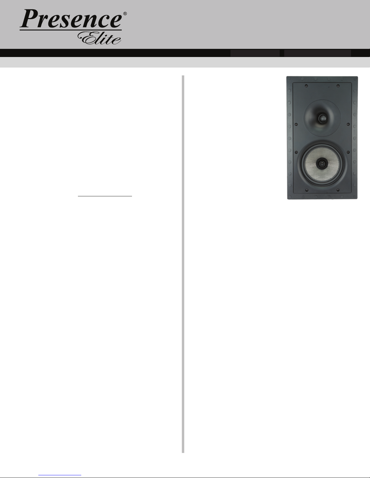
then all the speakers should be oriented portrait style. The tweeter
should be aimed toward the listening area. For other tweeter
positions see the tweeter positions chart to the left.
Placing the speakers within 18 to 36 inches of an adjacent wall,
as measured to the center of the speaker, will tend to increase
the effective bass output. Avoid placing the speakers less than
18 inches from an adjacent wall. When placing speakers near
a corner, avoid locating them an equal distance from the two
adjacent surfaces.
To achieve maximum performance we recommend that the
speaker cable be at least 16 gauge or larger for runs over 50 feet
(15m) and that the cable be double insulated. A CL-2 or CL-3 rated
cable may be required. Check local codes. “Zip cord,” which is
single insulated and is often made with clear insulation, should be
page 3 of 4Rev. ARev. A
page 2 of 4
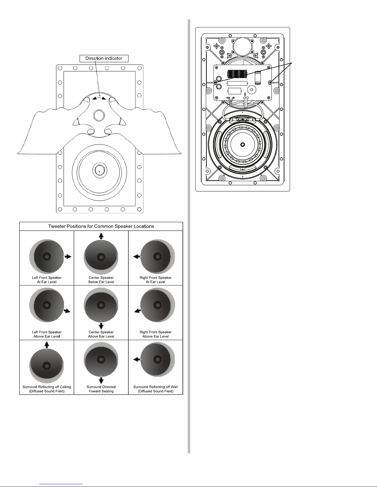
Two holes have been
provided to lock the
tweeter into place and
prevent rotation.
Should it be desirable to
lock the tweeter, install
two #6x3/8" (3.5mm
X 10mm) sheet metal
screws with at washers
in the provided holes.
(Hardware not included)