Contents
4GA 09.033/6.02 – (2011-07) – ©Oerlikon Leybold Vacuum
Product Identification 2
Validity 2
Intended Use 3
Trademarks 3
1Safety 6
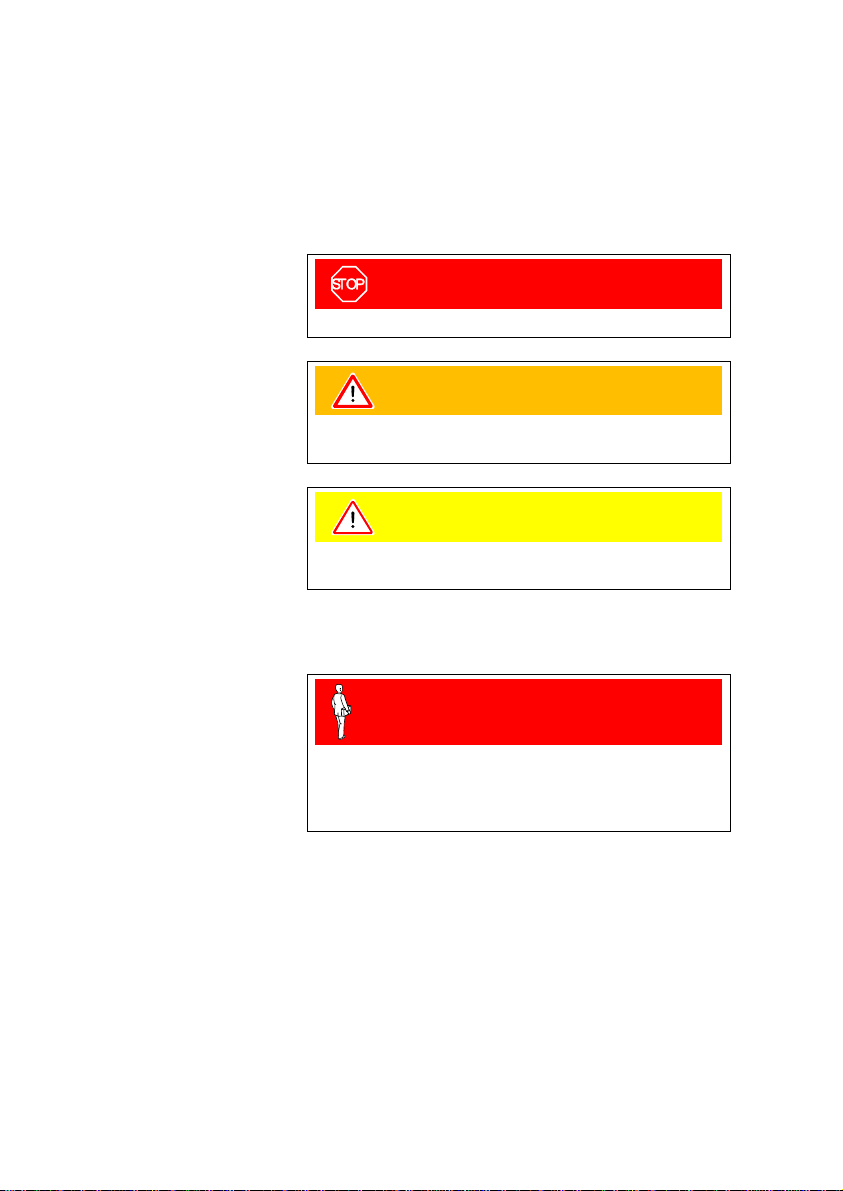
1.1 Symbols Used 6
1.2 Personnel Qualifications 6
1.3 General Safety Instructions 6
1.4 Liability and Warranty 8
2Technical Data 9
3Installation 14
3.1 Personal 14
3.2 Installation, Setup 14
3.2.1 Rack Installation 14
3.2.2 Installation in a Control Panel 20
3.2.3 Use as Desk-Top Unit 21
3.3 Mains Power Connector 22
3.4 SENSOR Connector 23
3.5 Interface Connector RS232 25
3.6 CONTROL Connector 26
4Operation 27
4.1 Front Panel 27
4.2 Turning CENTER ONE On and Off 29
4.3 Operating Modes 30
4.4 Measurement Mode 30
4.4.1 Operation 31
4.4.2 Turning the Gauge On/Off 32
4.4.3 Gauge Identification 33
4.5 Parameter Mode 34
4.5.1 Operation 35
4.5.2 Parameters 37
4.6 Test Mode 51
4.6.1 Operation 52
4.6.2 Parameters 53
4.6.3 Test Programs 55
5Communication (Serial Interface) 61
5.1 RS232C Interface 61
5.1.1 Data Transmission 61
5.1.2 Communication Protocol 63
5.2 Mnemonics 65
5.2.1 Measurement Mode 66
5.2.2 Parameter Mode 70
5.2.3 Test Mode 77
5.2.4 Example 82