OFFCARR ALHENA User manual

1
INSTRUCTION MANUAL
ALHENA
OFF CARR S.r.l. Via Dell’Artigianato II, 29 35010 Villa del Conte (PD) Italy
Tel. +39 049 9325733 Fax +39 049 9325734

2
INDEX
1. INTRODUCTION...........................................................................................4
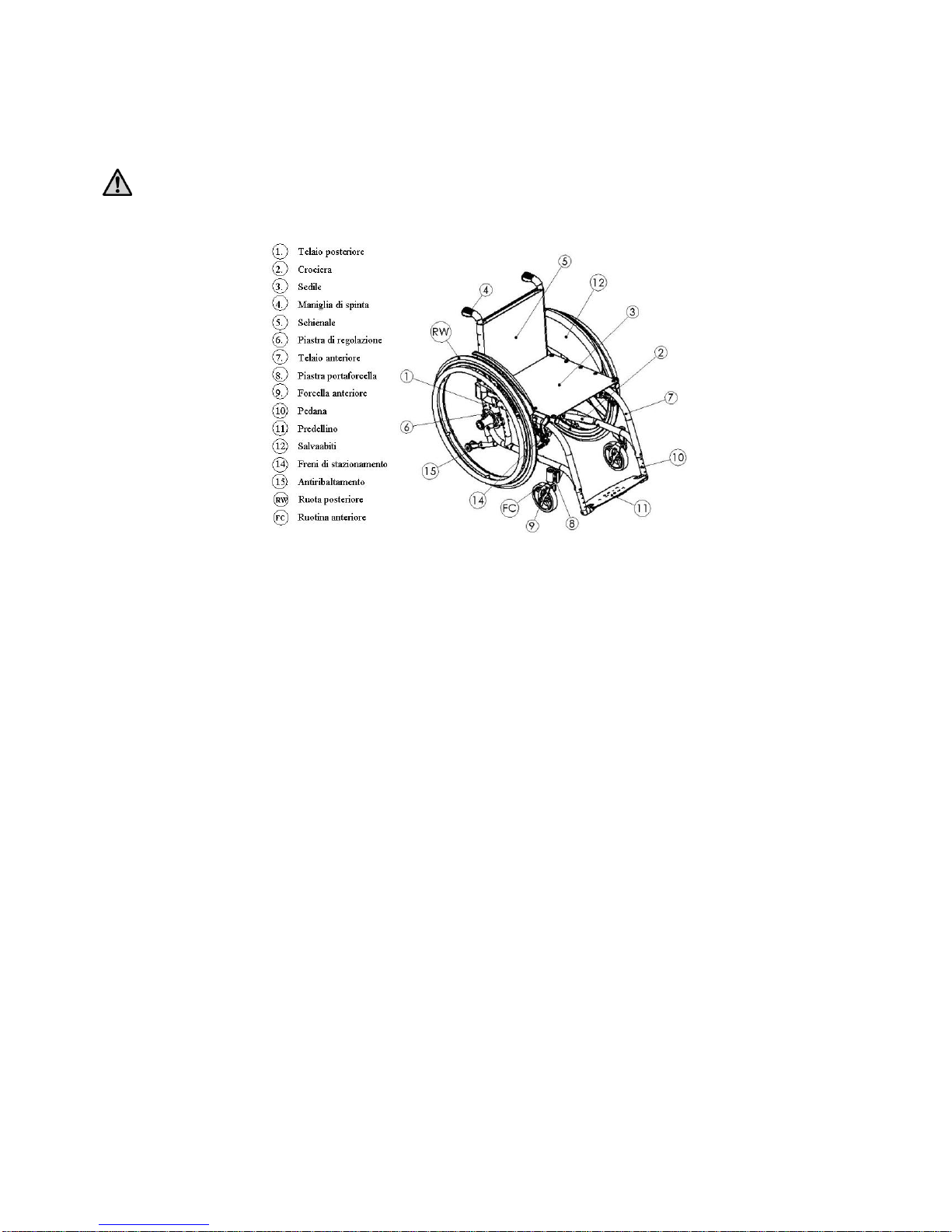
1.1 ALHENA DESCRIPTION..............................................................................................4
1.2 FEATURES ALHENA ..................................................................................................5
2. PREPARATION FOR USE............................................................................6
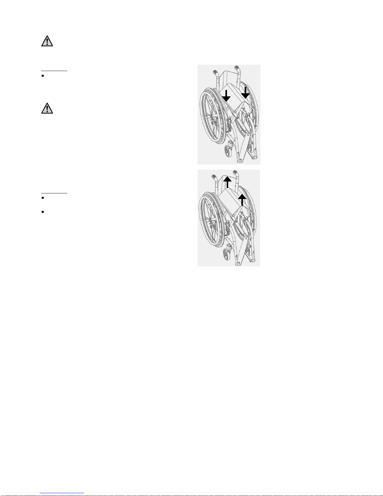
2.1 OPENING/FOLDING OF THE ALHENA WHEELCHAIR ........................................................6
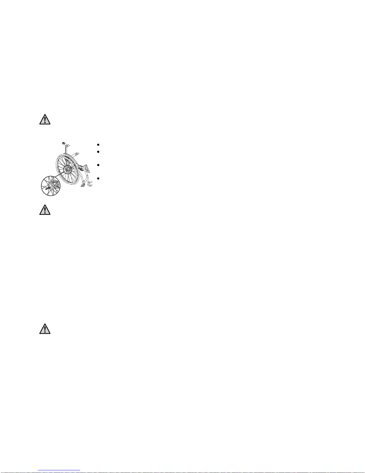
2.2 REAR WHEELS ASSEMBLY AND RELEASE.......................................................................7
2.3 PNEUMATIC PRESSURE CHECK......................................................................................7
2.4 FOOTREST POSITIONING ...............................................................................................7
2.5 CHECKING THE BRAKES ...............................................................................................8
2.6 CHECKING THE ACCESSORIES .......................................................................................9
3. SETTING UP ALHENA...............................................................................10
3.1 SELECTION OF THE REAR HEIGHT SEAT AND GRAVITY CENTER. ...................................10
3.2 SETTING THE FRONT HEIGHT OF THE SEAT...................................................................11
3.3 SETTING THE PERPENDICULARITY OF THE FRONT FORK SUPPORT PLATE.......................11
3.4 CLOTH-GUARDS SETUP...............................................................................................12
3.5 SETTING AND MAINTENANCE OF BRAKES....................................................................12
3.6 ADJUSTMENT OF THE BACKREST TENSION...................................................................13
3.7 BACKREST HEIGHT ADJUSTMENT................................................................................13
3.8 HIGTH ADJUSTABLE PUSHING-HANDLE .......................................................................13
3.9 DISTANCE FROM FOOTPLATE TO SEAT ADJUSTMENT....................................................13
3.10FOOTPLATE INCLINATION ADJUSTMENT......................................................................14
3.11WHEEL CAMBER ADJUSTMENT ...................................................................................15
4. ARMREST.....................................................................................................16
4.1 SPORT TIP UP AND DETACHABLE ARMREST .................................................................16
4.2 “L” TYPE ARMREST....................................................................................................16
5. ANTI-TIP DEVICE......................................................................................18
5.1 USE OF THE REVOLVING ANTI-TIP DEVICE...................................................................18
5.2 ADJUSTMENT OF THE ANTI-TIP DEVICE .......................................................................19
5.2.1 Adjustment through the rotation of the support plate...19
5.2.2 End terminal adjustment...............................................19
6. UMBALANCING SYSTEM.........................................................................20
7. EXTENDED WHEEL PLATE.....................................................................20
8. STRETCHED BAR.......................................................................................20
9. USE OF THE WHEELCHAIR....................................................................20
10. KEY MEASURES TO BE TAKEN TO LIMIT THE RISKS ASSOCIATED WITH MISUSE OF THE
WHEELCHAIR.............................................................................................22
11. MAINTENANCE, INSPECTIONS AND CONTROLS.............................23
12. TECHNICAL SERVICE..............................................................................24
13. GUARANTEE TERMS ................................................................................25
14. PACKAGING, SHIPPING AND DELIVERY ...........................................26
15. MATERIALS DIFFERENTIATION ..........................................................27

3
Thanks for choosing an OFF CARR wheelchair.
From more than 25 years OFF CARR listens and interprets customer’s needs by inventing highly
innovative and technologic solutions, always aimed at reducing daily mobility problems, with special
attention to product style and at improving quality of life for all customers.
OFF CARR has a certified system for quality management following the UNI EN ISO 9001:2008
regulation and a productive system following the UNI EN ISO 13485:2004 regulation. These
certifications offer prestige to the company and find confirmation in the quality of products and in
customer satisfaction.
OFF CARR also meet the 93/42/CEE directives, upgraded with the 2007/47/CE directive.
Before using or making adjustments on this device, carefully read what reported on this
manual.
In case of need, please contact an authorized dealer the manufacturer at the following
address
OFF CARR s.r.l.
Via dell’Artigianato II, 29
35010 Villa del Conte (Padova) Italy
Tel. +39 049 9325733 Fax +39 049 9325734

4
1. Introduction
The ultra light-weight wheelchair model ALHENA (folding frame), is non-intrusive medical devices, specifically designed to
reduce and counterbalance a physical handicap.
These wheelchairs are manually pushed on the back wheels, have many setups and a wide range of accessories to better meet
any customer need. Only qualified operators must prepare the device’s use and eventually.
The use of the wheelchairs or of parts of them is forbidden for different uses than the ones written on this manual.
1.1 ALHENA Description
The wheelchair AHENA is made with a foldable frame and a titanium crossbar. Other details are made with composite
materials, as carbon fibre, aluminum or steel alloys. Various frame colours are available and can be combined with various
coloured anodizing in the accessories and details set. The seat upholstery (3) and of the backrest (5) are, usually made in black
nylon cloth. The backrest can be also made with breathable material to increase the customer’s comfort. The backrest’s
upholstery is easily removable to make the cleaning and washing operations easier and its straightening is adjustable by acting
on the velstraps under the upholstery.
A comfortable compartment with closing zip can be added in the lower part of the backrest and another can be placed frontally
under the seat. The backrest is adjustable in height by acting on the frame-fixing screws.
The rear wheels (RW) are equipped with the quick releasing axle. The rear wheel support (6) allows an easier adjustment of
the rear wheel position, and finds the most comfortable setup for the user. On demand, for special needs, the wheelchair can be
equipped with the extended wheelplate for safer setup.
The front forks (9) have adjustable inclination and can lodge various wheel diameters (FC) at various height, to better answer
the setup and agility needs of users.
The front frame (7) is available with fixed or removable footrests. Considering possible setup restrictions, the footboards (11)
can be single or double and adjustable in height and inclination.
The wheelchair is supplied with carbon fibre sideguards (12) or in alternative made with aluminum or composite polymer as
per choice on the order form
The wheelchair can be configured also with sport armrest tip-up and detachable 22cm high from the seat, or with “L” shaped
armrest tip-up and detachable with selectable high from 22 up to 28 cm.
The brake device (14) standard or scissor model are adjustable to compensate different wheel size and different wheel setup.
The wide and sophisticated range of accessories available, allows to configure in a highly customized Alhena both
aesthetically and functionally.

5
1.2 Features ALHENA
Titanium folding frame
Titanium double crossbar
Two angle shaped fron frame
Multiple position for rear wheels
Tilt adjustable front fork
Carbon fiber clothe guards
Armrest foldable and detachable (if selected on the configuration)
Footrest according with the choice during configuration
Maximum load 115 Kg
The order form allow different setup and various combination of accessories.

6
2. Preparation for use
The preparation for use of these devices must be performed by qualified personnel both for evaluate the
suitability of the product and to provide the correct instructions to the user.
2.1 Opening/folding of the Alhena wheelchair
OPENING
Apply pressure with the open palm over the sides of the
seat (as shown on the drawing) until the seat will be
perfectly aligned to the frame.
Be careful not to wrap with the fingers the tubes of
the crossbar to avoid being pinched between the
frame and the crossbar.
FOLDING
If the footplate is not automatic, please fold up it to allow
the folding of the wheelchair;
pull up the fabric of the seat with both hands acting as
shown on the drawing.

7
2.2 Rear wheels assembly and release
Alhena wheelchair is normally shipped with the rear wheels already assembled while rigid frame wheelchair are shipped with
the rear wheels aside.
If necessary is possible to assembly or release the wheels as following:
• Ensure the brakes are released;
• Insert the shaft into the wheel by holding down the button;
• holding pressed the button of the shaft insert it into the bush on the frame of the wheelchair;
• release the button;
• check the efficiency of the engagement by trying to pull out the wheel without pressing the button and make sure it does not
come off.
It is suggested to verify the proper assembly and the efficency of the quick release axle before using the
wheelchair and always after performing releasing and assembly of the rear wheels to the frame.
Test for the right functioning of the quick release axle and proper assembly of the rear wheels
Ensure the brakes are released;
holding pressed the button of the shaft, pull out the
wheel from the hub;
still holding pressed the button of the shaft, insert it
into the hub on the frame of the wheelchair;
check the efficiency of the engagement by trying to
pull out the wheel without pressing the button and
make sure it does not come off.
For safety reasons it is important to repeat this check every time that for transportation reasons or
maintenance, the rear wheels are removed and reassembled to the frame.
2.3 Pneumatic pressure check
A periodical check of the pneumatic pressure may helps to keep the wheelchair efficient and more comfortable.
Verify the tire pressure value according to the value marked on the tyre.
Normally 7.5 BAR is the right value for high pressure rear tyres, and 2.5BAR is the maximum pressure for front wheels.
The above values are indicative as the specific value is always available on every tyre.
The pressure for the model Schwalbe Marathon Plus should always be kept from a minimum of 7 BAR to a
maximum of 9 BAR to prevent damage to the surface of the tyre itselves.
2.4 Footrest positioning
The wheelchair Alhena can be configured, depending on the model, with detachable or not detachable footrest. According with
the limits of configuration, the foot-plate can be single liftable automatically with the closing of the wheelchair, single or
separated manually liftable.
Once the wheelchair is open, rotate down the foot-plate in position ready for use.
If the foot-plate is single, pay attention to engage properly its connection pin to the corrisponding connector on the frame.

8
Predellini separati in
profilo di alluminio
Predellino unico in profilo
di alluminio
The automatic footrest, at the opening of the wheelchair, is automatically placed and the foot-plate, in absence of weight. Is
slightly tilted on one side. This condition is absolutely normal to allow the automatic closing. With a light weight on the plate,
this immediately takes a plain position.
In case of frame with removable footrests, the footrests are packed separately.
To insert the footrest:
open the wheelchair;
insert the footpads in their proper rotation housing starting from a position at 90° to the frame (as shown) and rotate it
inwards until the hooking mechanism snaps
To extract the footrest:
Press the hooking lever and rotate the footrest outwards
Remove the footrest from the hinge pin by pulling it upwards
Note: If necessary, you can turn the footrest to the inside of the wheelchair
2.5 Checking the brakes
To check the functioning and the efficiency of the parking brakes act as following:
Activate the brake (Fig. P, S, U);
Check if the wheels are blocked.
Pushing brake “OFF”
position
Pushing brake “ON”
position
Fig.P
Fig.O

9
The included brakes, except for
eventually drum brakes, have to
be used only as parking brakes and
not to decrease the speed of the
wheelchair.
To ensure the efficiency of the brakes it
is necessary to maintain the proper tire
pressure and check frequently the wear
of the clamping elements.
Pulling brake “OFF”
position
Pulling brake “ON”
position
Scissor brake “OFF”
position
Scissor brake “ON”
position
2.6 Checking the accessories
Any accessory required at the time of the configuration of the wheelchair is to be shipped separately. If so they should be
properly installed before using the wheelchair.
Fig.R
Fig.S
Fig.T
Fig.U

10
3. Setting up ALHENA
The wheelchair is shipped configured according to the order form. The selected parameters in the order form, should ensure the
best postural to match the customer’s needs. Keeping in consideration of potential conflicts of configuration is still possible to
perform other set up adjustment to fit better the user needs.
Please refer to authorized and qualified personnel only to perform any type of adjustment on the wheelchair.
3.1 Selection of the rear height seat and gravity center.
As advanced are assembled the rear wheels axis, as active and agile become the wheelchair but at the same time the stability
is reduced. As back the rear wheels axis are assembled, more stable is the wheelchair but more effort is required to push it.
Change of the rear height seat from ground:
by pushing the button in the center of the wheel hub
remove the rear wheel (vd.par.2.3);
Loosen the four screws "C" that secure the plate to
the frame;
Choose the new desired plate position and tighten
the four screws "C";
Change of gravity center:
Loosen and remove from the rear plate the wheel
bush “B”;
Select the new position for the bush from the three
holes “A” available, keeping the original sequence
for spacers and washer;
pay attention to the proper camber adjustment before to fix tightly the wheel bushes; (please check instructions 3.11)
Connect again the wheels to the chair checking the proper assembly as for instruction 2.3);
Operations to change the gravity center have always to be performed simmetrically.
Note: consider that the further the hub is connected, the more agile the wheelchair will be, and the further back it is
assembled, the lesser active but safer the wheelchair will be.
If any of the three “A” holes available on the plate satisfies the new setup requirements, the right plate can be inverted with the
left one, adding this way some other setting up possibilities.

11
Be sure to have chosen the same position in both wheel-keeping compasses on the back of the frame. Asimmetric combinations
produce instability.
Once changed the position of the back wheels, it is essential to adjust the front forks’ perpendicularity (see.
par.3.3) and the positioning of the parking brakes (see par.3.5) and, if necessary, to position the clothes-guards
(see par.3.4).
3.2 Setting the front height of the seat
It is possible to vary the front height of the wheelchair by changing the diametre of the front wheels or by choosing a different
position of the wheel on the fork:
Unscrew completely one of the “D” screws and remove
the “E” pern, on the side of the non-removed “D” screw,
being careful to the positions of the “F” spacers
If necessary, change the wheel
Position the wheel’s hole in level with the most
appropriate fork hole;
Insert the “E” pivot, being careful to the original positioning of the “F”
spacers;
Fix the “D” screw.
3.3 Setting the perpendicularity of the front fork support plate.
Once the front and rear height seat are set-up is necessary to verify and if necessary to adjust the perpendicularity of the front
fork support plate. This adjustment is important to reach the maximum agility and the best driving sensitivity fa the wheelchair.
Remove the protective cap “A”;
Loosen the two screw “B” that secure the fork support
plate;
Rotate the upper eccentric nut until the plate reaches
the perpendicular position;
tighten the two screws “B”;
place again the protective cap “A”.
Note: the two eccentric nuts have different profile. The upper nut with round profile allow a continuos adjustment of the plate
perpendicularity. In the lower position is assembled the exagonal profile eccentric nut. Is suggested to rotate it only
when the rotation of the upper nut is not enough to reach the right position.

12
3.4 Cloth-guards setup
Acta s follow if is necessary to change the carbon
fibre cloth-guards position:
loosen the screws “A” and “B”;
choose the new desired position of the corbon
fibre wing considering that the ideal gap
between tire and cloth guards is about 6 mm;
if needed the screw “B” can be romoved and
repositioned in one of the holes “C” more
convenient;
tighten the screws “A” and “B”.
3.5 Setting and maintenance of brakes
The supplied brakes are designed for parking only and they are not suitable to reduce the wheelchair speed.
If the rear wheel position have been changed from its original one, it is necessary to proceed with the brake adjustment. Alhena
wheelchair can be equipped with classic pushing or pulling brakes or scissor brakes.
Acta s follow to adjust the brake position:
leave the brake in OFF position (see par. 2.6 fig.O, R o T);
loosen without remove the screws “A” that secure the brake to the relevant support, and the screws “B” that fix the brake
holder to the wheelchair frame.
CLASSIC BRAKE:
move the brake on its support until the knurled pin will
be about 10 mm faar from the tire;
make sure the knurled pin will be perpendicular to the
tire, than properly tighten the screws “A” and “B” ;
if the knurled pin appare worn in the contact area with the tire, is possible
to turn it to find a better contact area or to change it with a new one;
SCISSOR BRAKES:
put the brake in ON position (see par. 2.6 fig.U)
move the brake along its support until it touch the tire;
return the brake in OFF position (see par. 2.6 fig.T) and
move the brake of 3-4mm, in the wheel direction, than
properly tighten the screws “A” and “B”;
verify the efficiency of the brake (see par. 2.6) and if
necessary repeat the adjustment procedure.

13
3.6 Adjustment of the backrest tension
The backrest tension can be adjusted by acting on the velcro
strapp belts:
leave up the cover “B” of the backrest upholstery.
Normally it is closed closed in the back side but
according with the configuration it can be fold down in
front;
adjust the upholstery tension opening or closing a little
bit the velcro belts under the upholstery;
fold down again the backrest upholstery cover “B”.
The belts “A” that adjust the backrest tension cannot be excessively tight in order to avoid to deform the geometry of the
wheelchair frame and to permit a smooth opening and closing frame operation.
3.7 Backrest height adjustment
The backrest heigth will be fixed during assembly according with order form selection. However is possible to change it over
the time.
If the wheelchair is equipped with push-handle is possible to move up or down them of a fiew centimeters acting as follow:
leave up the upholstery cover and open the tension belts
to reach the fixing screw “A”;
remove the screws “A”;
move up or down the push-handle extensions till the
desired height (the extension tube are already pre-holed
with steeps of two cm);
insert again the screws “A” and tighten them properly;
close again the belts with the right tension and fold
over the upholstery cover (see par.3.6).
Same procedure can be followed also if the push-handles are
height adjustable.
Similar procedure can be followed also to change the
extended backrest tubes when the wheelchair is configured
without push-handle.
3.8 Higth adjustable pushing-handle
If the wheelchair is equipped with height adjustable push-handle
is possible to adjust the mas follow:
Loosen the clamp unscrewing the knob “B”;
Choose the most convenient position for the push-handle;
Tighten properly the knob “B”;
Turn the knob”B” in a convenient position.
Nota: the knob “B” is a special spring lever. To change its position is possible to pull out the lever, turn it in the desired
position and release it again.
3.9 Distance from footplate to seat adjustment.
The telescopic footplate support is inserted into the front
frame of the wheelchair and secured through the screw “E”.
L’altezza è variabile con un passo di 2 cm:
Loosen and remove the screw “E”;
Move the footplate to reach the right distance from the
seat;
Insert again and tighten properly the screw “E”.

14
3.10 Footplate inclination adjustment
Single or separated footplates have the possibility to be
adjusted in their inclination:
Leave up the footplate to be able to reach the screw
“B”;
loosen the screw “A” if the footplate is single “A”;
loosen the screw “B” if the footplate are divided;
select the desired footplate inclination;
properly tighten the screws “A” or “B”.
Follow a similar procedure as above if the footplate is
automatic:
loosen without remove the screws”C”;
select the desired footplate inclination;
properly tighten the screws “C”.

15
3.11 Wheel camber adjustment
The rear wheel camber is fixed according with the choice on the order form. However is possible to change it if required.
On Alhena wheelchair is possible to change the wheel camber by replacing the rear bushes as follow:
remove the rear wheels (vd.par.2.3);
unscrew and remove the locking nut “A”;
replace the bush”B” with a new one with the desired
camber;
place the bush “B” in a way that the camber is in the
right direction and the two flat surface are about
perpendicular to the ground;
Insert the washer and the nut “A” keeping it loose in
order to be able to performe a fine adjustment of the
wheel camber;
Insert the rear wheels and check the distance
from them (d1e d2), measured in front and rear
at the level of the hub as indicated in the figure;
d1 and d2 have to be equal.
Check the distance “C” from frame to wheel
and verify if they are equal in the left and right
side;
Once the necessary correction are been performed and all the above tests are
passed, tighten properly the nut ”A” that secure the bushes to the holder plates.

16
4. Armrest
According with the order form configuration, Alhena wheelchair can be equipped with “Sport” tip up and detachable armrests
or “L” model tip up and fix or detachable armrests.
The armrest are not designed to lift up the wheelchair both with or without user.
4.1 Sport tip up and detachable armrest
To flip up the armrest:
Push the lever “A” to unlock the armrestc;
Rotate backword the armrest.
To remove the armrest:
Unlock the armrest by pushing the “A” lever
and rotate it a little backword;
Pull-up the armrest untill it is completely
removed from its back support.
Note: when the armrest has to be placed again on the wheelchair, be sure it
completely inserted on its back support in order to avoid unwanted rotation
of the armrest.
4.2 “L” type armrest
Usually the armrest is 22 cm height from the seat. On Alhena the height of the L type armrest can be increased of 2 or 4 cm to
increase the confort of the user:
Remove the screw “B” ;
Select the desired height and insert the screw previously removed;
Properly tighten the screw “B”
According with the order form configuration, the “L” armerst can be assembled to be rotated backword and also detachable
pulling-up it like the sport armrest.

17

18
5. Anti-tip device
Alhena wheelchair can be equipped with left or right antitip devices or both at the same time.
Never use the anti-tip wheels as transit wheels.
5.1 Use of the revolving anti-tip device
When not in use the anti-tip wheel is positioned under the frame:
To activate the anti-tip device is necessary to push down and rotate it backword until it will be locked in the proper position.

19
5.2 Adjustment of the anti-tip device
The position of the anti-tip is defined during the assembly. However is possible to change its distance from ground if
necessary.
5.2.1 Adjustment through the rotation of the support plate
Loosen without removing the screws “A”;
Rotate the anti-tip support until the desired distance of the
small wheel from the ground is reached;
Properly tighten the screws “A”.
5.2.2 End terminal adjustment
Remove the screw “B”;
Move the telescopic end terminal until the small wheel is in
the right position;
Insert the screw “B” and fix it properly.

20
6. Umbalancing system
On Alhena wheelchair is possible to assembly the umbalance pedal
necessary sometime to help assistant to overcome some steeps or to
facilitate the movement on the gravel.
On Alhena the umbalancing pedals are connected to the frame using
the holes available on the frame to locate the rear wheel support
plate.
NOTE: the umbalancing pedal is incompatible with the anti-tip device, they cannot be assemmbled in the same side of the
frame.
7. Extended wheel plate
The standard rear wheel support plates can be replaced by
special extended wheel plates to increase the stability of the
wheelchair to meet some special requirements.
The back position of the extended wheel plate move in front the baricenter of the wheelchair plus user complex. This special
setup make the wheelchair more stable but less agile and more hard to pus hit.
8. Stretched bar
The stretched bar is a device added to the backrest to keep
stable the geometry of the back frame when the back-rest is
very high or the wheelchair is very large or when the
configuration require it for safety reasons or for choice of
the user.
NOTE: OFFCARR reserve always the right to verify the technical compatibility of the stretched bar with other caracteristics of
the wheelchair configuration.
The stretched bar is always removable to allow to fold the wheelchair for transport.
9. Use of the wheelchair
In order to move safely and to effectively use the wheelchair, it is recommended to always consult qualified
personnel.
Here are some suggestions and recommendations for proper use of the wheelchair, also aimed at maintaining the security
features in time and duration:
The brake has only a stationary function and should never be used as a service brake to slow down the wheelchair in
motion.
To ensure the efficiency of the brakes, maintain the tires properly inflated and check every 3 months the knurled locking
pins’ wear (see par. 2.4 e 2.6).
The arm rests are not designed to lift the wheelchair
Anti-tilt wheels aren’t to be used under any circumstances as transit wheels
Do not lean too far forward because, by moving the centre of gravity too much, you may tip.
Table of contents
Popular Medical Equipment manuals by other brands

Inventec Appliances
Inventec Appliances Chiline S68 instruction manual

Gima
Gima 27850 User manual and assembly instructions

Biosense Webster
Biosense Webster LASSO Instructions for use

Johnson & Johnson
Johnson & Johnson Biosense Webster LASSO 2515 Instructions for use

Blatchford
Blatchford Silcare Breathe SBTTLP22L user guide

Siemens
Siemens Healthineers MAGNETOM Sempra Operator's manual