manuals.online logo
Brands
  1. Home
  2. •
  3. Brands
  4. •
  5. Offshore
  6. •
  7. Controllers
  8. •
  9. Offshore 3350-HTPO User manual

Offshore 3350-HTPO User manual

HOLDING TANK PUMP OUT CONTROLLER
Part Number: 3350-HTPO Holding Tank
Pump Out Controller
INSTALLATION AND OPERATING INSTRUCTIONS
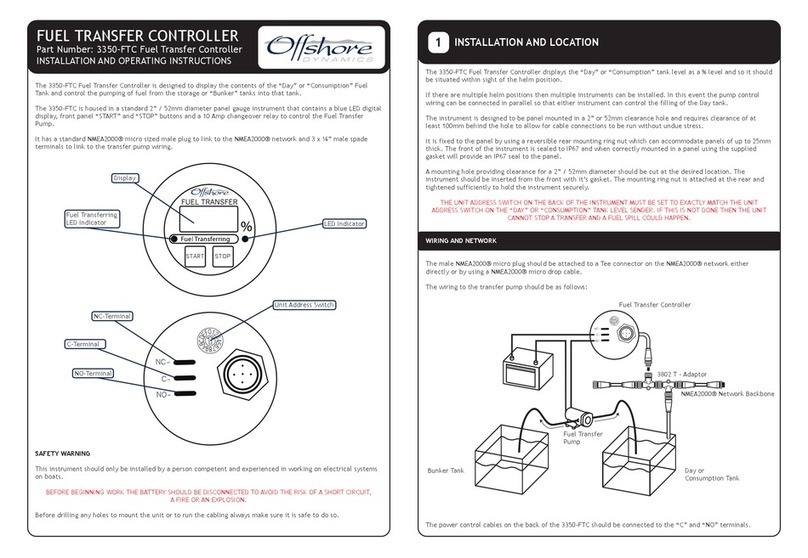
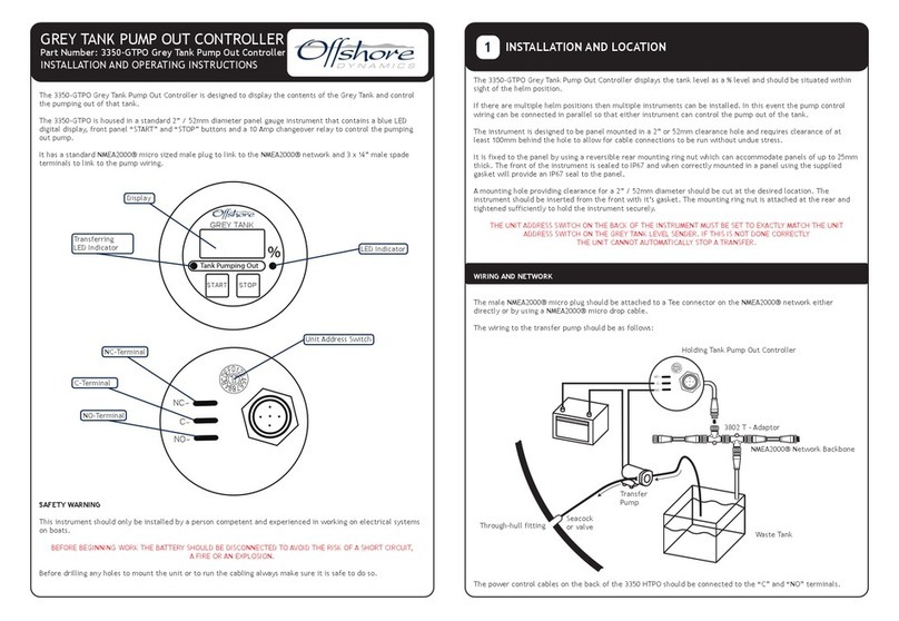
The 3350-HTPO Holding Tank Pump Out Controller is designed to display the contents of the Holding Tank and
control the pump out of the Holding Tank.
The 3350-HTPO is housed in a standard 2” / 52mm diameter panel gauge instrument that contains a blue LED
digital display, front panel “START” and “STOP” buttons and a 10 Amp changeover relay to control the Transfer
Pump.
It has a standard NMEA2000® micro sized male plug to link to the NMEA2000® network and 3 x ¼” male spade
terminals to link to the transfer pump wiring.
SAFETY WARNING
This instrument should only be installed by a person competent and experienced in working on electrical systems
on boats.
BEFORE BEGINNING WORK THE BATTERY SHOULD BE DISCONNECTED TO AVOID THE RISK OF A SHORT CIRCUIT,
A FIRE OR AN EXPLOSION.
Before drilling any holes to mount the unit or to run the cabling always make sure it is safe to do so.
The 3350-HTPO Holding Tank Pump Out Controller displays the tank level as a % level, it should be situated within
sight of the helm position.
If there are multiple helm positions then multiple instruments can be installed. In this event the pump control
wiring can be connected in parallel so that either instrument can control the pump out of the tank.
The instrument is designed to be panel mounted in a 2” or 52mm clearance hole and requires clearance of at
least 100mm behind the hole to allow for cable connections to be run without undue stress.
It is fixed to the panel by using a reversible rear mounting ring nut which can accommodate panels of up to 25mm
thick. The front of the instrument is sealed to IP67 and when correctly mounted in a panel using the supplied
gasket will provide an IP67 seal to the panel.
A mounting hole providing clearance for a 2” / 52mm diameter should be cut at the desired location. The
instrument should be inserted from the front with it’s gasket. The mounting ring nut is attached at the rear and
tightened sufficiently to hold the instrument securely.
THE UNIT ADDRESS SWITCH ON THE BACK OF THE INSTRUMENT MUST BE SET TO EXACTLY MATCH THE UNIT
ADDRESS SWITCH ON THE HOLDING TANK LEVEL SENDER. IF THIS IS NOT DONE CORRECTLY
THE UNIT CANNOT AUTOMATICALLY STOP A TRANSFER.
WIRING AND NETWORK
The male NMEA2000® micro plug should be attached to a Tee connector on the NMEA2000® network either
directly or by using a NMEA2000® micro drop cable.
The wiring to the transfer pump should be as follows:
The power control cables on the back of the 3350 HTPO should be connected to the “C” and “NO” terminals.
INSTALLATION AND LOCATION
1
LED Indicator
LED Indicator
Display
STARTSTOP
0
F
E
D
C
B
A
9
8
7
6
5
4
3
2
1
NC
C
NO
Unit Address Switch
3802 T - Adaptor
Holding Tank Pump Out Controller
NMEA2000® Network Backbone
0
F
E
D
C
B
A
9
8
7
6
5
4
3
2
1
NC
C
NO
Through-hull fitting
Seacock
or valve
Waste Tank
Transfer
Pump
NC-Terminal
C-Terminal
NO-Terminal
Tank Pumping Out
HOLDING TANK
The 3350-HTPO Holding Tank Pump Out Controller can be operated in either Manual or Automatic modes.
MANUAL OPERATION
When the user wants to empty a tank he simply presses the green START button which will cause the relay to start
the transfer pump if the level in the Holding Tank is more than 10%.
The user can stop the transfer at any time by pressing the red STOP button.
AUTOMATIC OPERATION
The unit is designed to automatically stop the transfer, when the level in the tank falls below 10%.
DURING TRANSFER
Whilst pumping out the red LED will flash to indicate that a transfer is in progress.
As soon as the tank level has reached 10% the relay will stop the transfer automatically.
Please note that the user can stop the transfer at any time by pressing the red STOP button.
If the ship’s power is removed during the pump out the transfer will stop. For safety reasons when the power is
restored the unit will NOT restart the transfer unless the START button is pressed again or the automatic start
feature is enabled and the tank level is below the user settable threshold.
MAINTENANCE
The 3350-HTPO controller can be cleaned with mild soap and water. Do NOT use solvents or abrasive or pressure
washers as these could damage the front of the instrument.
OPERATION
2
DOC NO. 00112 Rev. 2.0
Copyright © 2016 Offshore Dynamics Ltd. All rights reserved.Our policy is one of continuous product improvement so product
specifications are subject to change without notice. Offshore Dynamics products are designed to be accurate and reliable. However,
they should be used only as aids to vessel monitoring, and not as a replacement for traditional navigation and vessel monitoring
techniques. NMEA2000® is a registered trademark of the National Marine Electronics Association.
Offshore Dynamics Ltd
Unit 10 -11 Milton Business Centre, Wick Drive,
New Milton, Hampshire, BH25 6RH, United Kingdom
Tel: +44(0)1425 610022 Fax: +44(0)1425 614794
Email: [email protected] Web: www.osukl.com
STARTSTOP
Transferring
Transferring can
be manually stopped
any time
Tank Pumping Out
HOLDING TANK

Other Offshore Controllers manuals

Offshore 3350-FTC User manual

Offshore

Offshore 3350-FTC User manual

Offshore 3350-GTPO User manual

Offshore

Offshore 3350-GTPO User manual

Popular Controllers manuals by other brands

Emerson TARTARINI FL Series instruction manual

Emerson

Emerson TARTARINI FL Series instruction manual

Presys DCY-2050 manual

Presys

Presys DCY-2050 manual

Watlow Electric F4S Series user manual

Watlow Electric

Watlow Electric F4S Series user manual

National Instruments NI 8352 user manual

National Instruments

National Instruments NI 8352 user manual

Eaton EVER-Tap Installation, operation and maintenance instructions

Eaton

Eaton EVER-Tap Installation, operation and maintenance instructions

Tempco TEC95040 Installation & operating manual

Tempco

Tempco TEC95040 Installation & operating manual

Siemens 3VT9500-3MN00 operating instructions

Siemens

Siemens 3VT9500-3MN00 operating instructions

MDT AMI series Technical manual

MDT

MDT AMI series Technical manual

Techtrol TLIC Instruction and programming manual

Techtrol

Techtrol TLIC Instruction and programming manual

CD Automation REVEX 1Ph 30A user manual

CD Automation

CD Automation REVEX 1Ph 30A user manual

ATA DCB-05V2 manual

ATA

ATA DCB-05V2 manual

Samson 3271 Original instructions

Samson

Samson 3271 Original instructions

KIOUR FA3F quick start guide

KIOUR

KIOUR FA3F quick start guide

Qorvo ACT88326 manual

Qorvo

Qorvo ACT88326 manual

Dover Petro Vend FSC3000 installation manual

Dover

Dover Petro Vend FSC3000 installation manual

ISSI IS31IO7326 Guide

ISSI

ISSI IS31IO7326 Guide

CRE Technology UNIGEN manual

CRE Technology

CRE Technology UNIGEN manual

OBELUX CSW-DCW manual

OBELUX

OBELUX CSW-DCW manual

manuals.online logo
manuals.online logoBrands
  • About & Mission
  • Contact us
  • Privacy Policy
  • Terms and Conditions

Copyright 2025 Manuals.Online. All Rights Reserved.