RISK OF ELECTRIC SHOCK - Dangerous and poten-
tially fatal voltages are present when working on this
equipment. Before installation or beginning any trou-
bleshooting procedures, the electric power to this equip-
ment must be disconnected and locked out as described
by OSHA Standards. Units suspected of being faulty
must be removed and returned to Ogden for inspection
and/or repair. They contain no user serviceable compo-
nents.
To help minimize the possibility of fire or shock hazards,
do not expose this instrument to rain or excessive
moisture. This control is not to be used in hazardous
locations as defined in Articles 500 and 505 of the
National Electric Code.
Do not use this instrument in areas subject to
hazardous conditions such as excessive shock,
vibration, dirt, moisture, corrosive gases or oil. The
ambient temperature of the areas should not exceed
the maximum rating specified in Section 3, on previous
page.
Unpacking:
Upon receipt of the shipment remove the instrument
from the carton and inspect the unit for shipping dam-
age. If any damage due to transit is noticed, report and
file a claim with the carrier. Write down the model num-
ber, serial number, and date code for future reference
when corresponding with our service center. The serial
number (S/N) and date code (D/C) are located inside
the control.
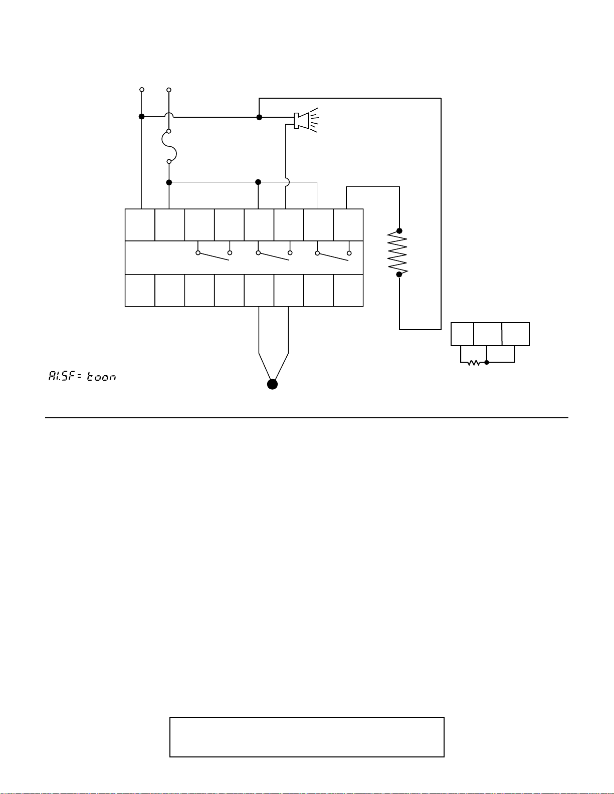
Mounting:
Make panel cutout to dimensions shown below right.
Insert the controller into the panel cutout. The maxi-
mum panel thickness is 1⁄8" (3.2mm).
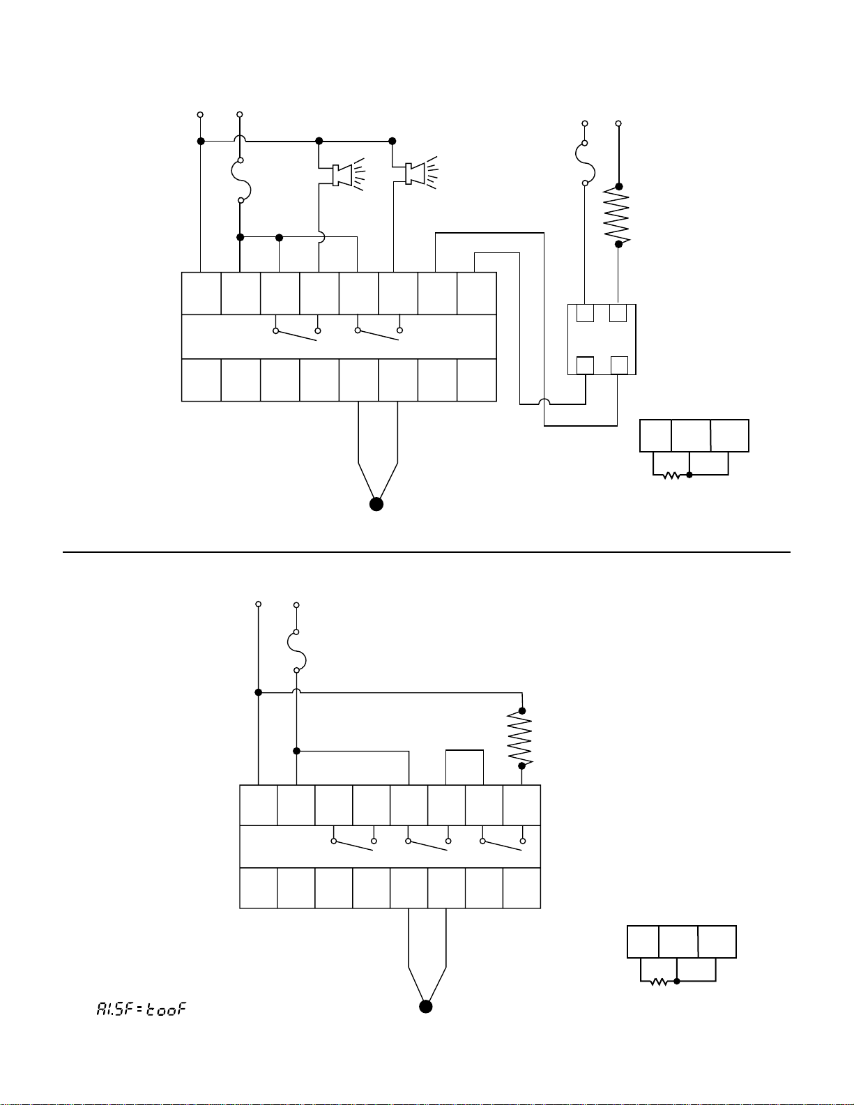
Wiring Precautions:
•Before wiring, verify the label for correct model num-
ber and options.
•Care must be taken to ensure that maximum voltage
ratings specified in Section 3 on previous page are
not exceeded.
•It is recommended that power to these instruments
be protected by fuses or circuit breakers rated at the
minimum value possible.
•All units should be installed inside a suitably ground-
ed metal enclosure to prevent live parts being acces-
sible to human hands and metal tools.
•All wiring must conform to appropriate standards of
good practice, national and local codes and
regulations. Wiring must be suitable for the maximum
voltage, current, and temperature ratings expected in
the system.
•Only “stripped”leads should be used for thermocou-
ple connections to prevent compensation and
resistance errors.
•Take care not to over-tighten the terminal screws.
•Unused control terminals should not be used as
jumper points as they may be internally connected,
causing damage to the unit.
•Verify that the ratings of the output devices and the
inputs as specified on page 3 are not exceeded.
•Electric power in industrial environments contains a
certain amount of noise in the form of transient volt-
ages and spikes. This electrical noise can enter and
adversely affect the operation of microprocessor-
based controls. For this reason we strongly recom-
mend the use of shielded thermocouple extension
wire which connects from the sensor to the controller.
This wire is a twisted-pair construction with foil wrap
and drain wire. The drain wire is to be attached to
earth ground at the sensor end only. We carry both
type J and type K in our stock.
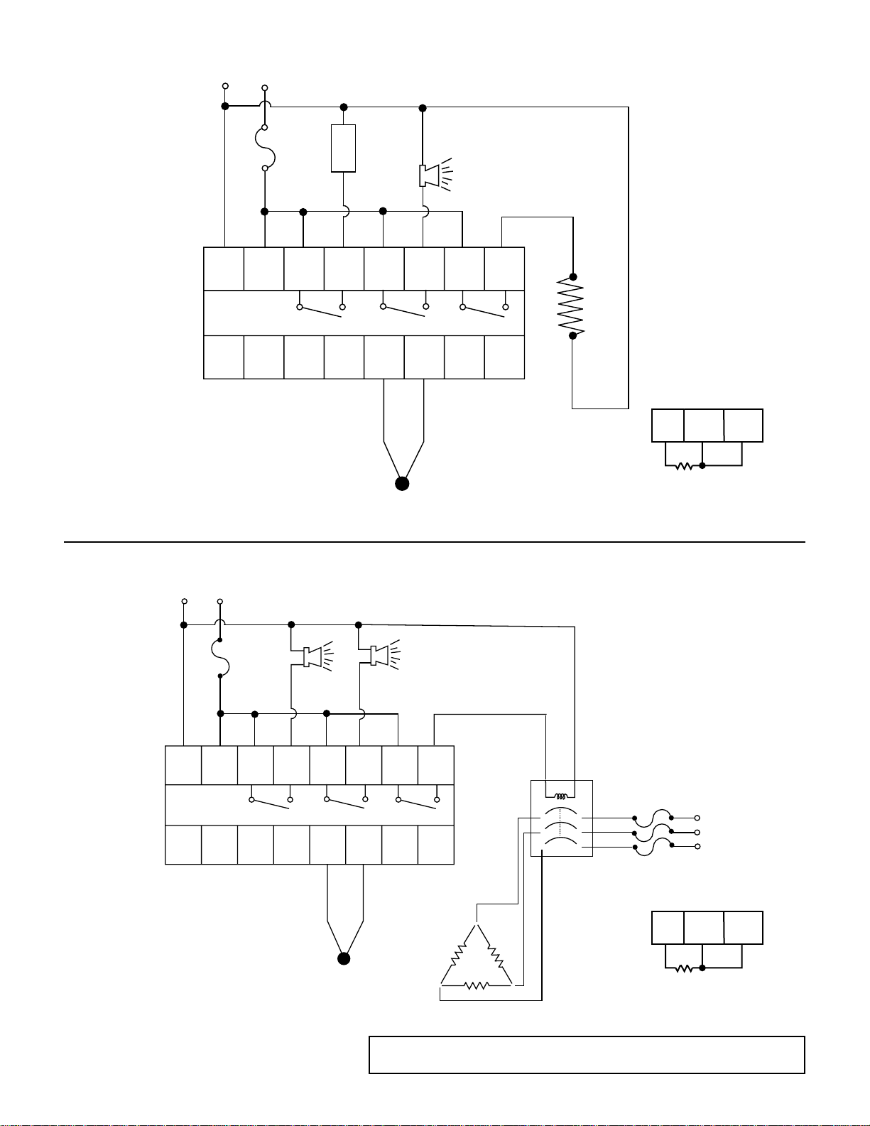
NOTE: The use of motor starters in place of magnetic
contactors should be avoided. They have very large
inductive loads that can damage the controller's relay.
Section 4: INSTALLATION