OK International MX-DS1 User manual

1
With power applied, the tip temperature can be > 300°C. Failure to observe the following
precautions may lead to injury to users or damage the equipment:
• Do not touch any metallic parts of the hand-piece
• Do not use near flammable items
• Do not use unit for any function other than described in this manual
• Use only genuine OK International replacement parts
• Use in a well ventilated area
• Do not use the equipment with wet hands
• Connect only to properly grounded outlets to prevent risk of electric shock.
• Always place hand-piece back into the work stand to prevent accidental
burning of oneself or surrounding objects.
• This appliance is not intended for use by persons (including children) with
reduced physical, sensory or mental capabilities, or lack of experience and
knowledge, unless they have been given supervision or instruction concerning
use of the appliance by a person responsible for their safety.
• Children should be supervised to ensure that they do not play with the
appliance.
Although the systems offer superior EOS (Electrical Overstress) protection, periodic
checks of the instrument cord should be incorporated into standard operator
maintenance procedures.
Waste Electrical and Electronic Equipment Directive -WEEE (2002/96/EC).
When this product is no longer required, if it cannot be re-used,
we ask our customers not to dispose of it as unsorted municipal
waste but to appropriately recycle the product. In Europe, please
contact your OKInternational distributor who can advise the
recycling options available.
WARNING
!

2
INTRODUCTION
The MX-DS1 is a hand-held desoldering tool which utilizes shop air to create a powerful
Venturi vacuum to clean through-holes quickly and efficiently. Paper solder collection liners
within the hand-piece barrel are easy to maintain and are an improvement upon traditional
glass tubes. Shop air is required for operation.
ACCESSORIES & SPARES
MX-DCF1
DS1 Filter Pack; 15 Chamber Liners, 6 Fume Filters
MX-DCF1L
DS1 Chamber Liners (pack of 40)
MX-MCF1F
DS1 Fume Filters (pack of 20)
MX-DAR1
Air Regulator and Filter with Fittings
AC-TC-P
Desolder tip Cleaner (Pack of 12)
AC-CB1-P
Desolder Chamber Cleaning Brush (Pack of 25)
AC-CB2-P
Desolder Tube Cleaning Brush (Pack of 6)
MX-DVC-1
Venturi Cartridge for Desolder Gun
MX-DSL1
DS1 Chamber Seal
MX-DSL2
DS1 Cartridge Seal
MX-DSB
Desolder Gun Swivel Bushing
MX-DLA
Desolder Gun Latch Adjustment (Pack of 10)
MX-DMK1
DS1 Maintenance Kit
CHOOSING THE CORRECT
GEOMETRY
Select a tip with an inside diameter
larger than the lead diameter. Select a
tip with an outside diameter that is
approximately the same size as the
pad.
A standard STDC cartridge can
desolder a maximum lead length of
0.0170." For fast, safe removal of
devices that are difficult to reach on
densely populated boards, or to remove long pin connectors, try the STDC long reach
cartridges. They are identical to standard STDC tip cartridges, but with a 0.46" long extension
at the tip.
CHOOSING THE CORRECT TEMPERATURE (SERIES)
Start with a 600 Series cartridge, switching to a
700 Series only where absolutely necessary; for
example, when working with ground planes or
multi-layer boards. For long reach tips, start with
a 700 Series cartridge.
For extremely heavy loads tied to ground planes,
or very thick multi-layer boards, 800 Series
cartridges may be necessary.
Inside Outside
Part Number
Dia.
Dia.
600
700
800
LONG
long reach
(A)
(B)
Series
Series
SERIES
Reach*
800 series
0.025"
0.055"
STDC-002
STDC-102
STDC-802
N/A
N/A
0.030"
0.066"
STDC-003
STDC-103
STDC-803
STDC-703L
STDC-803L
0.040"
0.070"
STDC-004
STDC-104
STDC-804
STDC-704L
STDC-804L
0.050"
0.080"
STDC-005
STDC-105
STDC-805
STDC-705L
STDC-805L
0.060"
0.090"
STDC-006
STDC-106
STDC-806
N/A
N/A
0.095"
0.125"
STDC-007
STDC-107
STDC-807
N/A
N/A
** When using long reach cartridges, 600 series heat delivery is insufficient for fast, safe device
removal. Therefore, long reach desolder tips are only available in 700 and 800 Series.
Correct
Too Small
Too Large

3
CHOOSING THE CORRECT DESOLDER CARTRIDGE
Proper tip cartridge selection is important for getting the best results from your Metcal System.
Choosing the right tip cartridge will maximize your performance at the lowest possible
temperature. Since changing the tip cartridge is so quick and easy, there is no need to
compromise.
ATTACHING THE AIR HOSE TO THE DESOLDER HANDPIECE
1. Make sure the system is turned off.
2. Clamp the Desoldering Power Cord to
the air line using the clamp, making
sure that the end of the Power Cord is
four inches beyond the end of the air
line
3. Attach the desoldering air line to the
DS1 hand-piece by using the swivel
fitting. A wrench is not needed, but the
connection should be as tight as your
fingers can make it.
4. Attach the other end of the Air Line to
your air supply, using a filter/regulator
to maintain the proper psi. Operating
the desoldering tool above 100 psi could cause the air line to rupture. The tool
works best when the air supply is set at 80 psi.
PREPARING THE DESOLDER HAND-PIECE
1. Open the hand-piece by sliding the top grooved portion forward.
2. Pivot the top of the hand-piece open.
3. Apply a thin layer of silicone grease inside the top of the chamber. This will aid in
keeping the roof of the chamber clear of incidental solder splatter.
4. Inspect the chamber seal to be sure it is clean and is not cut or damaged.
INSERTING FILTERS INTO THE DESOLDER HANDPIECE
1. Open the hand-piece. CAUTION: THE TIP MAY BE HOT!
2. Insert a new Chamber Liner in the rectangular cavity. Be sure to orient the tab
toward the back of the hand-piece.
INSERTING/REPLACING TIP CARTRIDGES INTO THE DESOLDER HAND-PIECE
1. Make sure the system is turned off.
2. Pull out the cartridge
using the Cartridge
Removal Pad
3. Insert the tip cartridge
into the desoldering
hand-piece by pushing in
the “back end” of the
cartridge (the end without
the tip) as far as it will go.
Notice that the tailpipe must be oriented down.
4. Turn on the system. The new cartridge should heat up to temperature quickly.

4
MAINTENANCE: CLEANING THE COLLECTION CHAMBER
WARNING: ALTHOUGH THE DESOLDER TOOL CAN BE OPENED AND CLEANED
WHILE THE SYSTEM IS ON, THE CARTRIDGE WILL BE HOT. USE EXTREME
CAUTION WHEN OPENING THE TOOL SO AS TO AVOID BURNING YOUR
FINGERS OR HAND ON THE EXPOSED CARTRIDGE
1. Open the Desoldering Handle and
remove the Chamber Liner. The
liner has a convenient lift-out tab to
facilitate removal.
2. In addition to replacing the
Chamber Liner when full, you
should periodically scrape any
solder or resin from the inside of the
upper half of the handle in the area
around the Cartridge tailpipe.
3. Apply a layer of silicone grease to
the surface after it is scraped clean.
Check that the chamber seal surface is clean before closing the handle.!
4. Two cleaning brushes are included with your system. Use these with Isopropyl
Alcohol or detergent to clean flux and solder residue from the chamber and
cartridge seals.
NOTE: SILICONE GREASE WILL CONTAMINATE ELECTRONIC CONNECTIONS
AND SHOULD BE USED WITH CARE AROUND ELECTRONIC PARTS.
The Venturi Filter will collect resins and will need to be replaced as often as use dictates. After
time, the passageways below the filter will
also clog with resin. When this happens,
follow the procedure below.
1. Open the Desoldering Handle and
remove the chamber filter.
2. Squirt flux cleaner in the passage,
and then pull the trigger to suck
the solvent through the Venturi.
Repeat until Venturi is clear.
MAINTENANCE: REPLACING THE VENTURI
If vacuum is still low after checking and cleaning the
Venturi, it will have to be replaced.
1. Open the Desoldering Handle.
2. Remove the Chamber filter.
3. Use an appropriate slotted screwdriver to
remove the Venturi cartridge. The cartridge
should screw out normally. Do not force.
4. Use a torque driver to install the Venturi
Cartridge to a torque of 10 to 15 inch-
pounds.
MAINTENANCE: CLEANING THE
DESOLDERING HANDLE
1. Remove the Desoldering Cartridge from the handle.
2. Disconnect the power cord and air hose from the handle.
3. Remove the cartridge and chamber seals.
4. Clean the handle in a mild vapor degreaser or ultrasonic bath.
5. Allow time for the tool to dry, and then replace the seals.

5
MAINTENANCE: CLEANING THE WORKSTAND
The exterior of the workstand can be cleaned with a soft bristle brush and a mild detergent.
The cradle can be cleaned separately by removing the attachment screw, located on the
bottom of the workstand.
MAINTENANCE: REPLACING THE SWIVEL BUSHING
1. Turn off shop air.
2. Unscrew air hose from the desolder tool.
3. Using an adjustable wrench, unscrew the swivel bushing.
Note: the swivel bushing is secured in the tool with a sealant so it may be difficult to
remove.
4. When you remove the swivel bushing, you will see a spring. Keep it in place.
5. Make sure the area where the swivel bushing screws in is clean of foreign materials
(this may require removing the spring temporarily).
6. Wrap Teflon pipe sealant around the end of the swivel bushing and with the spring
in place, screw the swivel bushing into the back of the desolder tool using a torque
wrench to 30-50 in-lbs.
7. Screw in the air hose onto the swivel bushing.
8. Turn on shop air and check for leaks.
MAINTENANCE: REPLACING THE UPPER CHAMBER
For an illustration of many of the steps in this technique, see following page.
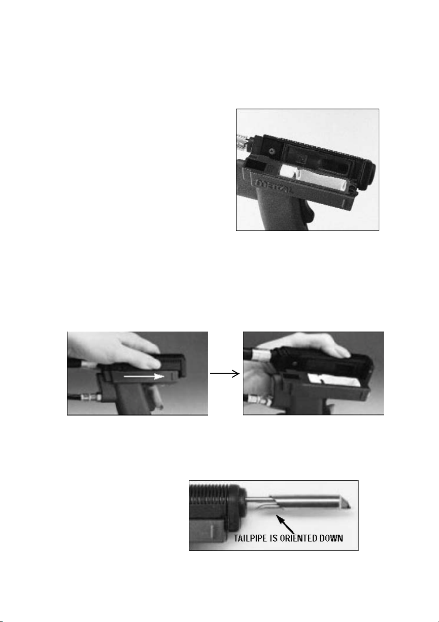
1. Remove the power cord from back of the upper chamber.
2. Open the upper chamber.
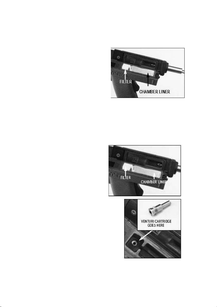
3. Insert a long, thin tool in the back hinge where the upper chamber hinges to the tool
handle assembly.
4. Push tool inwards and pull the upper chamber away from the tool handle assembly.
5. Completely remove upper chamber.
6. Remove old pins and springs from the front and back pin bores.
7. Insert two new springs, and two new hinge pins, into the pin bores on either end of
the tool handle assembly. Ensure that the smaller, tapered ends of the hinge pins,
are pointing outward.
8. Install upper chamber assembly onto tool handle assembly by pushing the hinge
pins into their bores until the arms of the upper chamber assembly will slide onto the
handle assembly. The hinge pins should slide out into their pilot holes in the arms
of the upper chamber.
9. Check the functioning of the slide latch and hinge by operating the latch, opening
and closing the upper body a few times. The parting lines (gaps) between the rear
of the chamber and the top rear of the right handle should be parallel.
MAINTENANCE: REPLACING CARTRIDGE SEALS
1. Turn off the system and remove the desolder cartridge.
2. Pry out the cartridge seal (at the front end of tool) by gently prying it out with a small
screwdriver, paper clip, or other blunt instrument.
3. Replace the cartridge seal by pushing it in.
MAINTENANCE: REPLACING CHAMBER SEALS
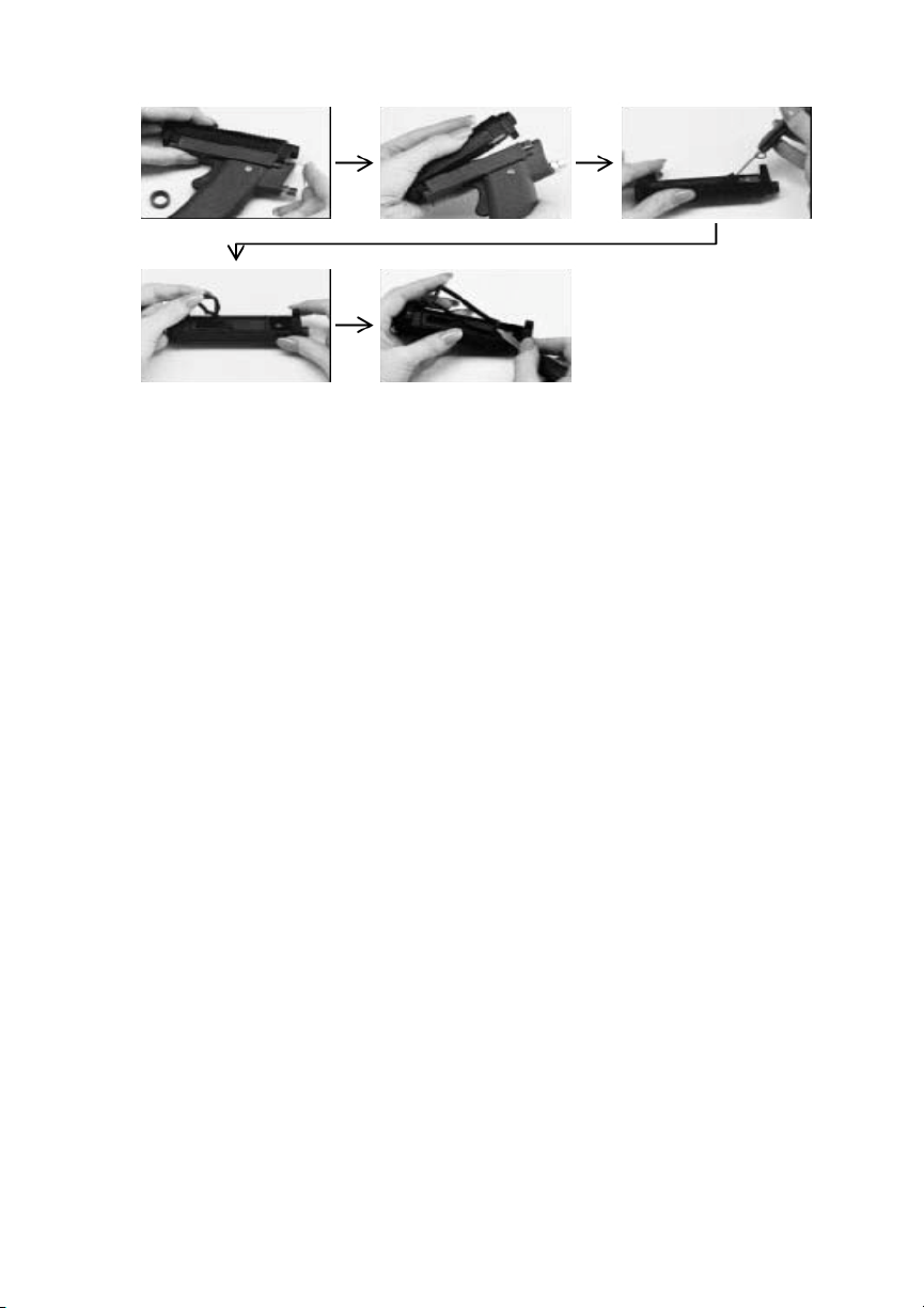
1. Remove the air line and power cord from the desoldering handle.
2. Open the desoldering handle and lay it down with the hinge side facing up toward
you
3. Before removing the hinge pins, cover the hinge area with your hand as you remove
the top. They are spring loaded and might shoot out of the tool as the top is
removed. Take the end of a paper clip and push it into the small hole at the front or
rear of the hinge. This will push the hinge pin into the tool. You can then wiggle the
top of the tool away from the hinge pin. Repeat this with the other hinge.
4. Remove the top half of the tool.
5. Remove the solder chamber seal using a knife.
6. To install the new chamber seal, start with a short side, and use a screwdriver or
other blunt tip to tuck the seal lip into the retaining grove

6
7. Next, tuck the other short side.
8. Finish with the long sides.
TROUBLESHOOTING GUIDE: DESOLDERING TOOL DOES Not REMOVE SOLDER
1. Check if the tip is heating up by applying solder to the tip. If it does not heat, follow
the steps under “Tip Will Not Heat” earlier in this manual.
2. Turn the power supply off.
3. Open the handle.
4. Replace the Chamber filter if it appears dirty and full of flux.
5. Replace the Chamber liner if it is full.
6. Lay the edge of your hand over the top of the collection chamber to provide a seal.
Press the trigger of the tool and verify that you feel a strong suction against your
hand.
7. If the suction is not strong, proceed to step 12. Ifthe suction is strong and you
replaced wither the chamber filter or liner, close the tool, insert a cartridge, turn the
system on and press the trigger while melting some solder with the tip.
8. If the solder is not sucked into the tool, clean the tip with a thin wire or Tip Cleaner.
9. If this does not help, turn the system off, remove the cartridge, and visually inspect
the cartridge seal and chamber seal for leaks (tears, nicks, debris). Close the tool,
remove the cartridge, and place your thumb over the front opening of the tool while
pressing the trigger.
10. If you do not feel a strong suction, try replacing the chamber seal.
11. If you still do not feel a strong suction, adjust the set screw under the front lip of the
top slide latch.
12. If the suction is weak, check the air pressure (80 psi is ideal).
13. If there is still no vacuum generated by the unit, check all the air lines to the handle
for cuts, kinks or obstructions.
14. Clean the Venturi. Squirt flux cleaner in the passage (or on a fresh Venturi), the pull
the trigger for a few seconds (with the handle open).
15. If this does not work, replace the Venturi cartridge as described in “Replacing the
Venturi”.
Warranty
OK International warrants the MX-DS1 against any defects in materials or workmanship for
one (1) year from the date of purchase by the original owner. This Warranty excludes normal
maintenance and shall not apply to any opened, misused, abused, altered or damaged items.
If the product should become defective within the warranty period, OK International will repair
or replace it free of charge at its sole option. The repaired or replacement item will be shipped,
freight prepaid, to the original purchaser. The warranty period will start from the date of
purchase. If the date of purchase cannot be substantiated the date of manufacture will be used
as the start of the warranty period.
Table of contents