manuals.online logo
Brands
  1. Home
  2. •
  3. Brands
  4. •
  5. Okamura
  6. •
  7. Indoor Furnishing
  8. •
  9. Okamura LIVE S Shelf User manual

Okamura LIVE S Shelf User manual

GXC293/2020-10
Shelf [High type]
Caution
●Secure enough workspace before assembly. Failure to do so may cause injury.
●Assembly must be conducted by two or more people. Failure to do so may cause injury.
●Use specified tools for assembly. Improper assembly, such as not completely tightening screws, may cause damage to
the product or cause the product to overturn resulting in injury.
●Take gloves off when using power tools. Gloves may get caught in tools causing injury.
●Be careful when handling the ends and backs of parts, and with the gaps between parts. Failure to do so may cause injury.
● Ensure that you have all the parts required.
● Prepare tools for assembly.
● When you inserting screws, lightly tighten
before completely tightening them.
● Handle the product with care.
●
Make sure there is about 300mm of space from the
ceiling to assemble the product from above
Assembly Preparations
Safety Instructions (Make sure to follow these instructions)
This indicates that improper handling may cause injury or property damage.
  Caution
Assembly Guide
Shelf Unit
Figure of completed assembly
● Are bolts completely tightened? ‥‥‥‥‥‥‥‥‥‥‥‥‥‥‥‥‥‥‥‥‥‥‥‥‥‥‥‥
●Are there any scratches, dirt, distortions or malfunctions? ‥‥‥‥‥‥‥‥‥‥‥‥‥‥
●Are there any packaging materials or trash on the floor? ‥‥‥‥‥‥‥‥‥‥‥‥‥‥‥
Lastly…
Make sure of the following items when assembling is complete.
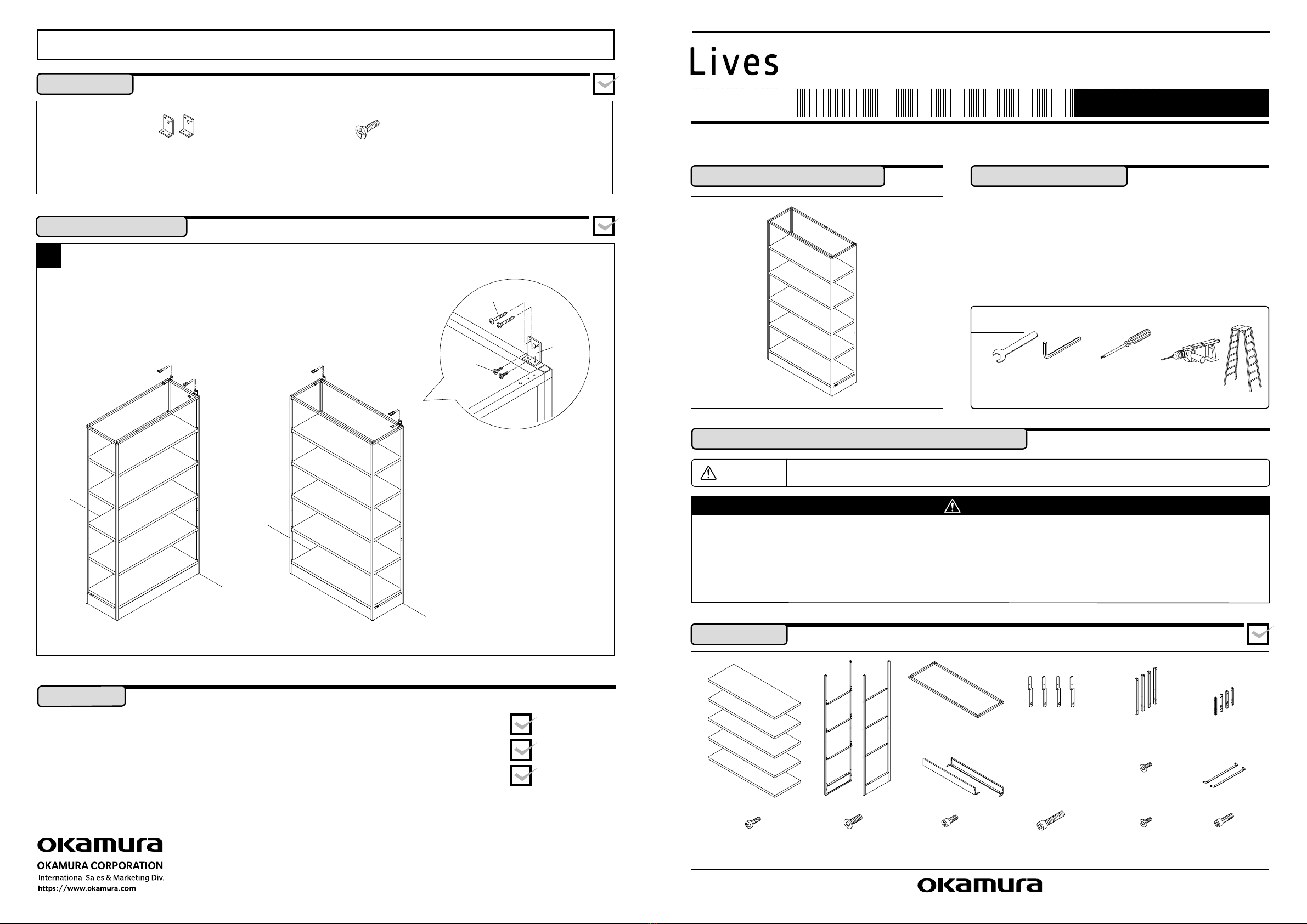
Attachment to wall
Wall
Wall
When attaching perpendicularly to the wall When attaching parallel to the wall
Purchase screws
for this separately.
Self-threading
flat head
screw
(M4x8L)
Wall
attachment
brackets
Self-threading flat head
screw (M4x8L) x4 pieces
Wall attachment brackets x2
*
The type of screws required for attachment to the wall will differ depending on the wall
s material. Purchase screws for this separately.
Follow the instructions to ensure proper assembly.
Assembly Instructions
Upper frame x1
Shelf x5 Side frame x2 Baseboard x2
Z bracket x4 Extension frame x4 Connector
bracket x4
Bracket x2
Self-threading
pan head screw
(M5x10L) x16 pieces
Ultra low
head screw
(M6x15L) x16 pieces
Hexagonal socket
head cap bolt
(M6x15L) x4 pieces
Hexagonal socket
head cap bolt
(M8x20L) x4 pieces
Special screw
(M6x12L)
x8 pieces
Ultra low head
screw (M6x15L)
x4 pieces
Hexagonal socket
head cap bolt
(M8x16L) x2 pieces
〈ShelfUnit(2236H)〉
Tools
Hexagon
wrench
(width across
flats 4mm)
Phillips-head
screw driver
Spanner
(13mm)
Electric drill
Stepladder
This guide will enable you to properly assemble and use <Lives Shelf>.
Read this guidebook thoroughly and fully understand its content before assembling the product.
1
① Attach the wall attachment brackets using the self-threading
flat head screws M4 by screwing them into the 2 holes on
the top of the upper frame.
② Attach the wall attachment brackets to the wall.
Method for attaching to wall
Make sure that you have all of the necessary parts before assembling.
Components
Make sure that you have all of the necessary parts before assembling.
Components
21
Follow the instructions to ensure proper assembly.
Assembly Instructions Follow the instructions to ensure proper assembly.
Assembly Instructions
Self-threading
pan head screw
(M5x10L)
Side frame
Z bracket
Self-threading
pan head screw
(M5x10L)
Self-threading
pan head screw
(M5x10L)
Panel
Connector panel
Hexagonal
socket head
cap bolts (M4x8L)
Hexagonal socket
head cap bolt (M8x20L)
Upper frame
Shelf
Hexagonal socket head
cap bolt (M6x15L) for base only
Ultra low head
screws (M6x15L)
Upper part of
side frame
Hexagonal socket
head cap bolt
(M6x15L)
Bracket
Connector
bracket
Extension frame
Special screw
(M6x12L)
②①
2
1
① Place the side frame on its side and insert the baseboard.
② Attach from the under side of the baseboard
using the self-threading pan head screw (M5x10L)
in 4 places.
③ Insert the Z bracket into the slit, and
attach using 2 self-threading pan head
screws (M5x10L) per bracket.
*
Attach the connector panel to the panel.
① Insert the panel connection fittings into the groove
of the connector panel.
② Insert the Hexagonal socket head cap
bolts (M4x8L) from the panel side to the
connector panel and fix them in place (3
locations).
Frame assembly-1
Mounting of end panel
① Insert the upper frame into the top part of
the frame, and attach using the hexagonal
socket head cap bolt (M8x20L) in 4 places.
*
Mount the end panel after assembling the frame.
4Frame assembly-3
5
*
Determine layout and connect before mounting the shelf if
you are connecting multiple units. (→P.3)
① Place the shelf on top of the bracket and attach using the ultra
low head screws (M6x15L) in 4 places. (Number of shelves: 4)
 Hold together firmly to ensure that there are no gaps between
the side frame and the shelf.
②Hold together firmly to ensure that there are no gaps between
the side frame and the shelf.
③ Remove the transparent sticker from the
Okamura logo on the baseboard. (Front and
back 2 pieces)
Mounting the shelf
Be careful not to pinch your fingers when
sliding in the shelf.
Caution
① First insert bracket to side frame, then connector bracket, and attach
using hexagonal socket head cap bolts (M8x16L) in 4 places.
② Insert the extension frame into the joint bracket and
attach using low head screws (M5x12L) in 2 places.
③ Attach the other side using the same method.
3Frame assembly-2
43
170
270
170
270
Connector plate
x4
Self-threading flat head
screw (M4x8L) x16 pieces
Pan head machine screw with
spring washer (M5x10L) x2 pieces
Cap nut
x2 pieces
Connecting
Pan head machine
screw with spring
washer (M5x10L)
Connectorplate
Self-threading flat head
screw (M4x8L)
Connectorplate
Self-threading flat head
screw (M4x8L)
Pan head machine
screw with spring
washer (M5x10L)
Cap nut
Cap nut
Connecting
Follow the instructions to ensure proper assembly.
Assembly Instructions
Figure of completed assembly Follow the instructions to ensure proper assembly.
Assembly Instructions
1
① The baseboard of the unit has half-punched holes.
Fully open the holes in the attachment areas.
*
When attaching at a 90°
degree angle, location of
appropriate holes might change depending on the
depth of the frame unit.
Half-punched holes
<Connecting side by side> <Connecting at 90°
degree angle>
2
Connecting at 90°
degree angle
① Attach the baseboard using using the pan head
machine screw with spring washer (M5x10L) and
cap nuts in 2 places.
② Attach the side frame using the connector plate
in 2 places. (Self-threading flat head screw
(M4x8L) 4 places)
③ Attach the upper frame using the connector
plate in 2 places. (Self-threading flat head screw
(M4x8L) 4 places)
Connecting side by side
① Attach the baseboard using using the pan head
machine screw with spring washer (M5x10L) and
cap nuts in 2 places.
② Attach the side frame using the connector plate
in 2 places. (Self-threading flat head screw
(M4x8L) 4 places)
③ Attach the upper frame using the connector
plate in 2 places. (Self-threading flat head screw
(M4x8L) 4 places)
Connecting the frame unit
Make sure that you have all of the necessary parts before assembling.
Components
65
Arrangetothesamedimensions
asthepreparedgate
Arrangetothesamedimensions
asthepreparedgate
<Connecting side by side> <Connecting at 90°
degree angle>
Low head self-threading
screw (M4x10L)
Low head self-threading
screw (M4x10L)
Gate
Gate x1
Low head self-threading
screw (M4x10L) x4 pieces
Follow the instructions to ensure proper assembly.
Assembly Instructions
Figure of completed assembly
Attaching to floor
Floor attachment
bracket
Floorboard
Hexagonal Phillips
head bolt (M6x40L)
Hexagonal nut
Anchor bolt
Floor attachment
bracket
Floorboard
Hexagonal Phillips
head bolt (M6x40L)
Hexagonal nut
Anchor bolt
Baseboard
Baseboard
Floor attachment bracket x4 Floorboard x4 Hexagonal Phillips head bolt
(M6x40L) x8 pieces
Hexagonal nut x8 pieces
*
The type of anchor nuts and bolts required for attaching to the floor will differ depending on the floor
s material. Purchase separately.
Follow the instructions to ensure proper assembly.
Assembly Instructions
1Connecting the Frame and Gate
<Connecting side by side> <Connecting at 90°
degree angle>
① Attach the gate to the top part of the frame using the low head self-
threading screw (M4x10L) in 4 places.
Make sure that you have all of the necessary parts before assembling.
Components
1
① Connect the floor attachment brackets to the
corner of the baseboard and determine the
attachment location.
②
Use an oscillating drill to drill a hole into the floor
where you plan on attaching, and attach the
anchor bolt.
③ Set the washer on the anchor bolt and mount the
frame unit.
④ Adjust the level of the frame unit, attach the
hexagonal nut (for use with M6) to the hexagonal
Phillips head bolt (M6x40L) and mount to the
floor attachment brackets.
⑤ Adjust so that the bolt touches the washer and
lock with the hexagonal nut.
⑥ Attach the anchor bolt attachment nut and
attach.
Mounting location of floor attachment brackets
*
Attach to the corner.
Method for attaching to floor
Make sure that you have all of the necessary parts before assembling.
Components

Other Okamura Indoor Furnishing manuals

Okamura Portone User manual

Okamura

Okamura Portone User manual

Okamura UCI Finora User manual

Okamura

Okamura UCI Finora User manual

Okamura 865SAR Installation guide

Okamura

Okamura 865SAR Installation guide

Okamura Nagare User manual

Okamura

Okamura Nagare User manual

Okamura LW User manual

Okamura

Okamura LW User manual

Okamura Lives User manual

Okamura

Okamura Lives User manual

Okamura Visconte User manual

Okamura

Okamura Visconte User manual

Okamura Zephyr light User manual

Okamura

Okamura Zephyr light User manual

Okamura Grata series User manual

Okamura

Okamura Grata series User manual

Okamura Striker User manual

Okamura

Okamura Striker User manual

Okamura Lives LW User manual

Okamura

Okamura Lives LW User manual

Okamura 865JAD Installation guide

Okamura

Okamura 865JAD Installation guide

Okamura Lives LW User manual

Okamura

Okamura Lives LW User manual

Okamura Legender User manual

Okamura

Okamura Legender User manual

Okamura Sphere User manual

Okamura

Okamura Sphere User manual

Okamura T1 Series User manual

Okamura

Okamura T1 Series User manual

Okamura Sabrina Smart Operation User manual

Okamura

Okamura Sabrina Smart Operation User manual

Okamura Sabrina User manual

Okamura

Okamura Sabrina User manual

Okamura CYNARA User manual

Okamura

Okamura CYNARA User manual

Okamura Arco 865JAT Installation guide

Okamura

Okamura Arco 865JAT Installation guide

Okamura Visconte User manual

Okamura

Okamura Visconte User manual

Okamura 865LAD Installation guide

Okamura

Okamura 865LAD Installation guide

Okamura 865XTW User guide

Okamura

Okamura 865XTW User guide

Okamura CP User manual

Okamura

Okamura CP User manual

Popular Indoor Furnishing manuals by other brands

Graham Field Lumex PATRIOT LIBERTY GF6570B-1 Installation & operation instructions

Graham Field

Graham Field Lumex PATRIOT LIBERTY GF6570B-1 Installation & operation instructions

Songmics Vasagle LWD64 manual

Songmics

Songmics Vasagle LWD64 manual

Hesperide ABSOLU 123833 Assembly instructions

Hesperide

Hesperide ABSOLU 123833 Assembly instructions

BUT ESTRAN J0G manual

BUT

BUT ESTRAN J0G manual

realspace Chase manual

realspace

realspace Chase manual

Next THORNLEY instructions

Next

Next THORNLEY instructions

CB2 CADET Assembly instructions

CB2

CB2 CADET Assembly instructions

Rauch M2811 Assembly instructions

Rauch

Rauch M2811 Assembly instructions

avaks nabytok REA AMY 16 Assembly instructions

avaks nabytok

avaks nabytok REA AMY 16 Assembly instructions

emob Miro 160x200 Assembly instruction

emob

emob Miro 160x200 Assembly instruction

pamo LOFT III manual

pamo

pamo LOFT III manual

Forte FRTD311 Assembling Instruction

Forte

Forte FRTD311 Assembling Instruction

GFW STOCKHOLM 2 DRAWER NIGHTSTAND Assembly instructions

GFW

GFW STOCKHOLM 2 DRAWER NIGHTSTAND Assembly instructions

EXPEDO BILLIE W2S Assembly manual

EXPEDO

EXPEDO BILLIE W2S Assembly manual

VISTA PRODUCTS ROMAN SHADES installation instructions

VISTA PRODUCTS

VISTA PRODUCTS ROMAN SHADES installation instructions

Mocka Hamptons Assembly instructions

Mocka

Mocka Hamptons Assembly instructions

modway EEI -1327 manual

modway

modway EEI -1327 manual

Walker Edison W60CMP Assembly instructions

Walker Edison

Walker Edison W60CMP Assembly instructions

manuals.online logo
manuals.online logoBrands
  • About & Mission
  • Contact us
  • Privacy Policy
  • Terms and Conditions

Copyright 2025 Manuals.Online. All Rights Reserved.