Controllo remoto
I - 2
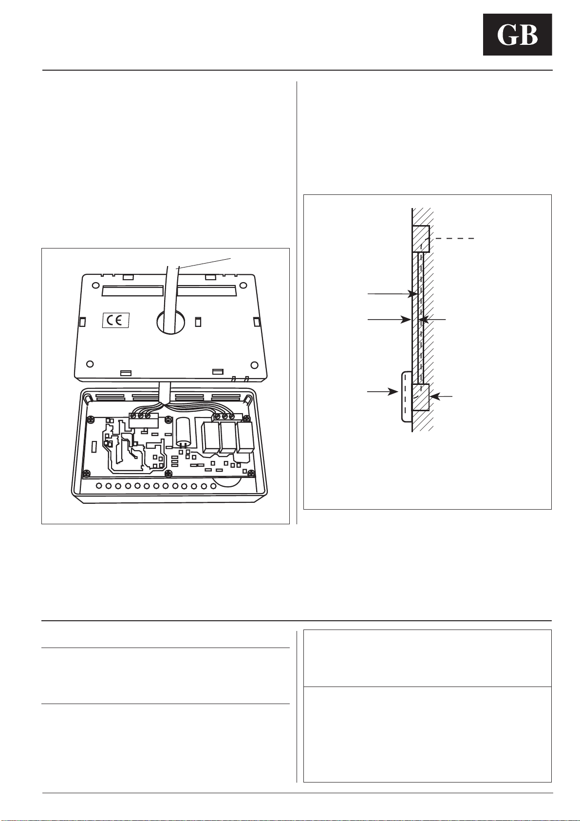
Montaggio
ATTENZIONE:
Prima di installare il comando remoto, togliere
NCNKOGPVC\KQPGGNGVVTKECXGTUQNWPKV´EJGCNKOGPVGT´KN
comando remoto. Le scariche elettriche possono causare
ferite e danni molto gravi alle persone.
+PHQTOC\KQPKIGPGTCNKGECTCVVGTKUVKEJG
IMPORTANTE: Leggere attentamente questo manuale prima
FKKPK\KCTGNŏKPUVCNNC\KQPG
• L’installazione deve essere eseguita da personale
specializzato rispettando la sequenza delle operazioni indicata
nello schema d’installazione.
• Eseguire l’installazione rispettando le normative di sicurezza
Nazionali in vigore.
• Dopo l’installazione eseguire il collaudo funzionale ed istruire
l’utente sul corretto funzionamento della macchina.
• Lasciare il presente manuale all’utente in modo che possa
essere consultato per le periodiche operazioni di manutenzione.
• Eliminare il materiale di imballaggio rispettando le vigenti
normative.
Ŗ+NRTQFWVVQTGTKſWVCSWCNUKCUKTGURQPUCDKNKV´GNCICTCP\KC
sarà nulla se non verranno osservate queste istruzioni di
installazione.
• Assicurarsi che il controllo non abbia subito danni durante
il trasporto; nel caso esporre immediato reclamo allo
spedizioniere. Non installare ne utilizzare controlli danneggiati.
• In caso di funzionamento anomalo spegnere l’unità, togliere
l’alimentazione elettrica e rivolgersi a personale specializzato.
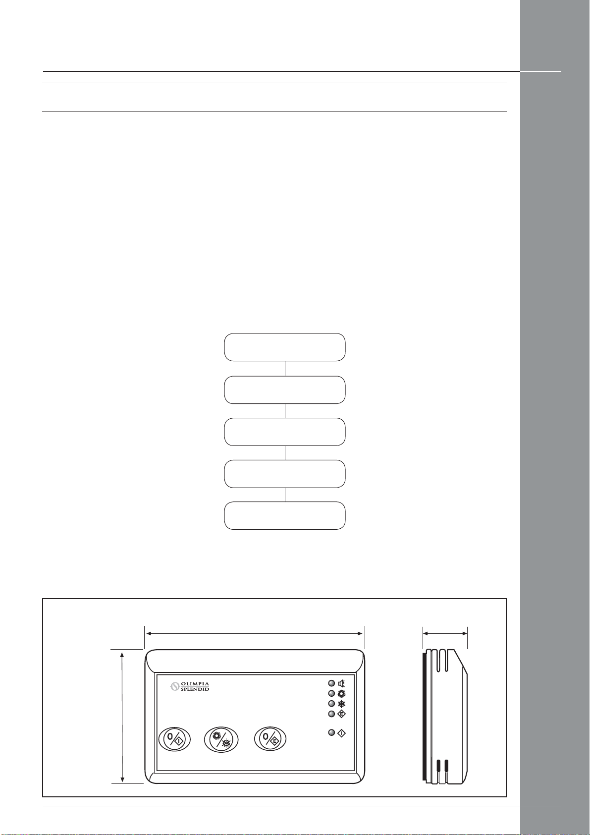
Modelli
Solo freddo / Pompa di calore
Prodotti che possono essere interfacciati con il comando
remoto 30AW.
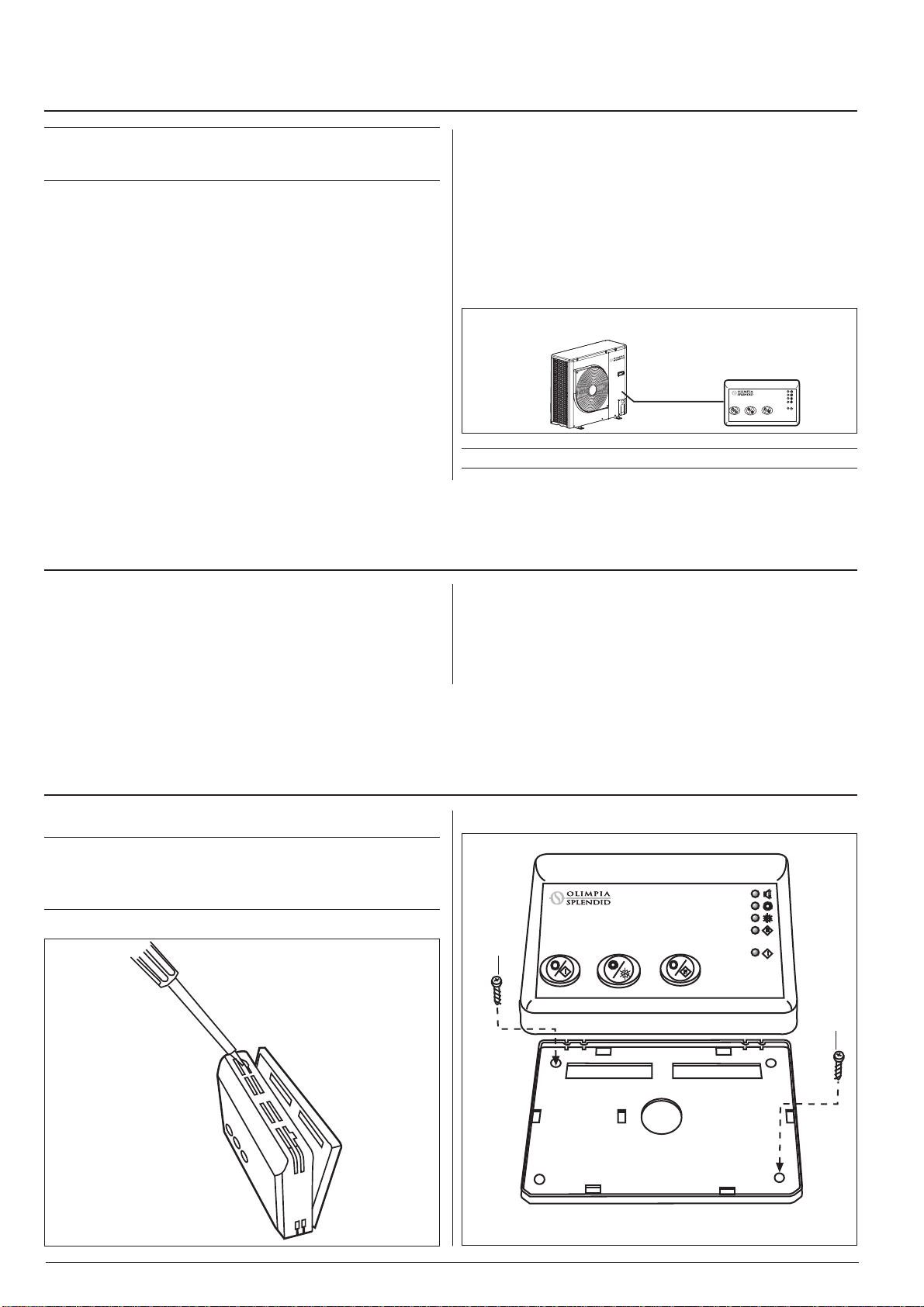
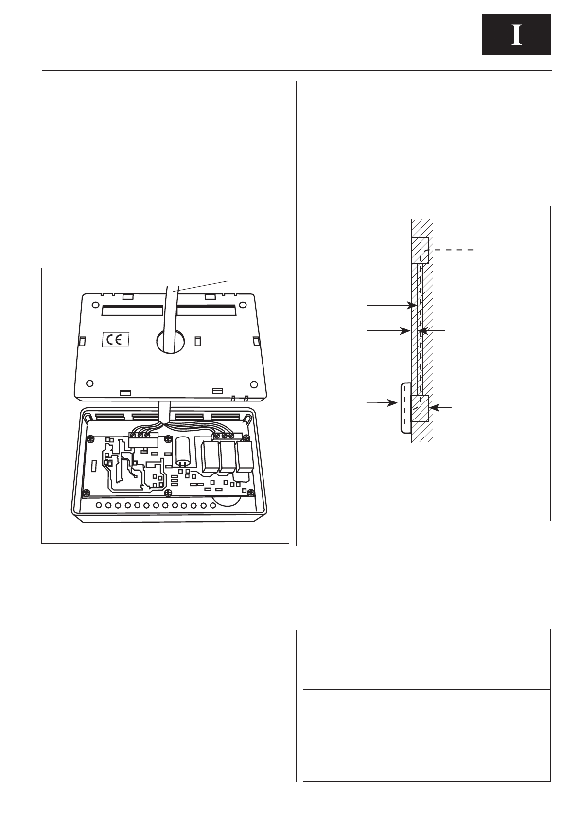
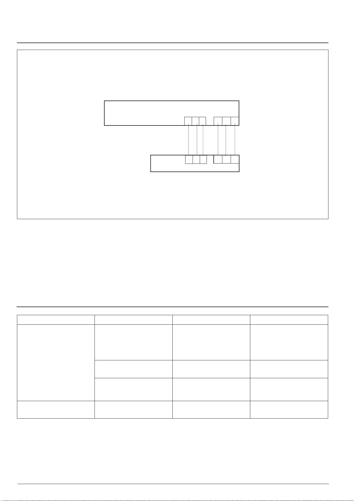
Cablaggio
• Il comando remoto deve essere collegato all’unità 30AW.
#NKOGPVC\KQPG
Il comando remoto non necessita di batterie per il funzionamento
corretto. Il comando remoto non funzionerà senza il collegamento
con l’unità 30AW.
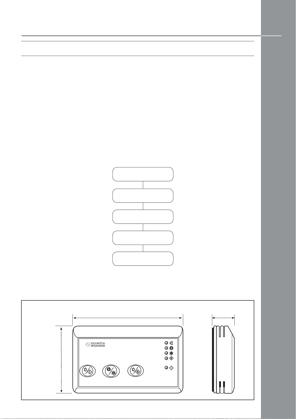
.KOKVKFKHWP\KQPCOGPVQ
Il comando remoto è stato disegnato per applicazioni interne in
ambienti residenziali e/o commerciali.
.CUWCVKRKECCRRNKEC\KQPGÂKNſUUCIIKQCRCTGVGCFCNVG\\C
accessibile dall'operatore senza limiti particolari solitamente
richiesti per apparecchiature analoghe aventi sensori di
temperatura interni.I limiti di impiego sono:
Temperatura massima di funzionamento +50°C
Temperatura minima di funzionamento +0°C
Temperatura massima di stoccaggio +70°C
Temperatura minima di stoccaggio -10°C
Umidità relativa massima di funzionamento 80% u.r.
Umidità relativa massima di stoccaggio 95% u.r.
Tensione di alimentazione nominale 12 V ac (+/- 10%)
5EGNVCFGNNWQIQFKPUVCNNC\KQPGGFKPUVCNNC\KQPG
a
a
Comando remoto
• Togliere l'alimentazione elettrica dell'unità.
016#UWNNGWPKV´#9GUGIWKTGEQPſIWTC\KQPGOQFQ
remoto “REM” .
a 8KVKſUUCIIKQ