Olis VDM-200 User manual

«OLIS»Ltd.
Peeling Machine VDM-200
Operating Manual
VDM-00.00.000OM
(incl. the Manufacturer’s Certificate)
Odessa

Изм.
Лист
№ докум.
Подпись
Дата
Лист
2
VDM-00.00.000OM
Разраб.
Коротченко
Проверил
Федоренко
Н. Контр.
Утвердил
Затв.
Верещинський
Peeling Machine
VDM-200
Лит.
Листов
27
ТОВ «ОЛИС»
Table of Contents
1. Description and Operation
1.1 Purpose of the Product
1.2 Technical Specifications
1.3 Product Structure
1.4 Product Operation
1.5 Electrical System
1.6 Package
2. Usage as Intended
2.1 Operating Limits
2.2 Security Measures
2.3 Product Preparation for Use
2.4 Product Usage
2.5 Operation in Extreme Conditions
3. Maintenance Procedures
3.1.1 Maintenance Procedures, General Guidelines
3.1.2 Maintenance Intervals
3.1.3 Disassembling and Assembling of the Head and Roller
3.1.4 Product Operability Check
3.1.5 Product Preservation and De-Preservation
3.2 Maintenance of the Product Integral Parts
4. Search for Causes of Failures and Malfunctions, and Ways of their
Elimination
5. Storage
6. Transportation
7. Disposal
8. Completeness
9. Resources, Periods of Service and Storage, and Manufacturer’s
Warranty
10. Preservation
11. Certificate of Packaging
12. Acceptance Certificate
13. Product Transfers While in Service
13.1 Transportation Limitations
13.2 Product Send and Receive
13.3 Data on Product Securing While in Operation
14. Repairs and Performance Records Due to Bulletins and
Instructions
15. Notes on Maintenance and Storage
Annex
Page
4
4
5
6
6
9
9
9
9
9
11
12
13
13
14
15
15
16
17
17
18
19
19
19
20
21
21
22
23
24
24
24
25
25
26
27

Изм
Л
исИзм
№ докум.
Подпись
Дата
Лист
3
ВДМ-00.00.000 РЭ
This Operating Manual (OM) is included in the design documentation for the
peeling machine VDM-00.00. - hereinafter referred to as «the Product», and intended
for giving the engineering employees and the maintenance personnel of operational
services insights into purpose, construction, technical characteristics, operating
principles, possible malfunctions and their elimination, features of service and repair of
the Product, as well as with the manufacturer's guarantees.
The product is designed and manufactured in accordance with the requirements of
the following regulatory documents:
Technical regulations of safety of machines (approved by the CMU as of 30.01.
2013, No. 62),
Technical regulations of low-voltage electrical equipment (approved by the CMU
as of 29.10.2009 No.1149);
Technical regulations on electromagnetic compatibility of equipment (approved
by the CMU as of 29.07.2009 No. № 785)
DSTU EN ISO 12100:2014. General principles of the engineering design. Risk
Assessment and Risk Reduction (EN ISO 12100:2010, IDT);
DSTU EN 60204-1:2015 Safety of machines. Electrical equipment of machines.
Part 1: General requirements (EN 60204-1:2006, А1:2009; АС:2010, IDT);
DSTU EN 1672-1-2001 Equipment for the food industry. Requirements for safety
and hygiene. Basic provisions. Part 1. Safety requirements (pr EN 1672-1: 1994, IDT);
DSTU EN 1672-2-2014 Equipment for the food industry. Requirements for safety
and hygiene. Basic provisions. Part 2. Requirements for hygiene (EN 1672-2: 2005 / A1:
2009, IDT);
GOST 12.2.124-90 Food equipment. General safety requirements;
The Product complies with the requirements of the Technical Regulations for
safety and health protection when used for its intended purpose and observance of the
safety measures set forth in this Operating Manual.
The Operating Manual applies to the following modifications (see Table 1):
Table 1. 1 Modifications of peeling machines.
Machine
Modification
Designation due to the
main design document
VDM -200G
VDM-00.00.000
VDM -200P
VDM -00.00.000-01

Изм
Л
исИзм
№ докум.
Подпись
Дата
Лист
4
ВДМ-00.00.000 РЭ
In order to improve the design and operational characteristics, some slight changes
in the design of the Product are possible, which are not reflected in this Manual.
The warning sign in this Operating Manual requires special care, taking into
account the health hazard and possibility of damage to the Product.
The user must develop a safety instruction and technical maintenance regulations
for the Product with due consideration of conditions, operation rate and the requirements
of this OM.
1. Description and Operation
1.1 Purpose of the Product
The Product is designed for buckwheat (VDM-200G modification) and millet
(VDM-200P) hulling at groat-milling plants in the course of their processing into groats.
It is used at groat-milling plants during groat production. Parameters and dimensions of
the Product comply with the requirements for equipment used at grain processing plants.
Any other use of the Product is considered unintended, the manufacturer is not
liable for the loss resulting from the unintended use of the Product.

Изм
Л
исИзм
№ докум.
Подпись
Дата
Лист
5
ВДМ-00.00.000 РЭ
1.2 Technical Specifications
Modification
VDM-200G
VDM-200P
Productivity, t/h
1,0
1,5…1,8
Pre-installed electric power capacity, kW
2.2
3
Mains Voltage, V
Frequency, Hz
380±20
50
380±20
50
Rotation frequency of the roller, rot/min
580
580
Airflow rate for aspiration, m3/h
300
300
Weight, kg
285
305
Overall dimensions, mm. length
width
height
925
420
1032
925
420
1032

Изм
Л
исИзм
№ докум.
Подпись
Дата
Лист
6
ВДМ-00.00.000 РЭ
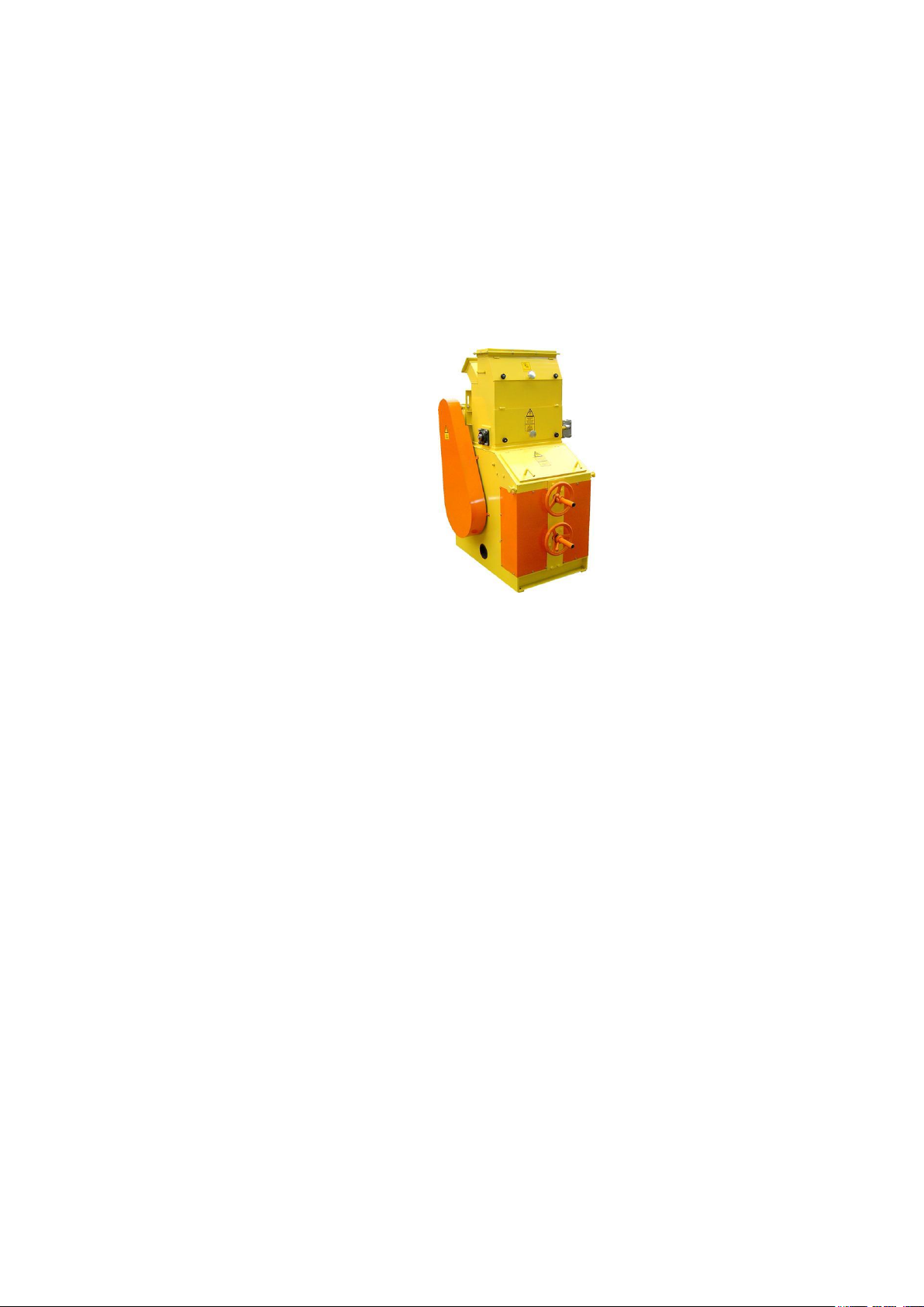
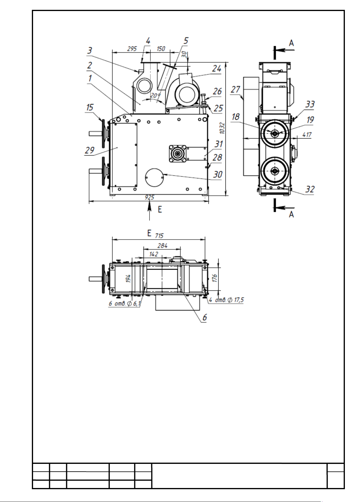
1.3. Product Structure
The Product (see Fig. 1) consists of a bed 1, a feed unit 2 with a regulating valve 3,
a grain supply duct 4, an aspiration duct 5. There is a duct 6 on the bed for feeding out
the processed material, on bearings 7 there is an operating roller 8, on bearings 9 there is
an axis 10 with levers 11 to which the body 12 is fixed with the head 13, equipped with a
working clearance adjustment mechanism consisting of screws 14, nuts 15 with
flywheels and bearings 16 fixed to the rack 17, lock nuts 18 with fixing bolts 19. The
head is secured to the frame with bolts 20. Installed on the axis of the working roller
there is a pulley 21 connected to a belt 22 with a pulley 23 of the electric motor 24
secured on the motor-mounting plate 25 with a screw 26 of a belt drive tension protected
by a mantle 27. The bed apertures are closed by covers 28, 29, 30, and cover plates 31.
The rack to the bed is secured with bolts 32. The bed has hooks 33 for carrying out
rigging works.
The working roller is made of abrasive material; so is the head for buckwheat
processing, the head for millet processing is made of rubber.
No engineering changes or modifications to the Product are allowed without
the manufacturer’s agreement.
1.4. Product Operation
The Product operates as follows. The slide valve and gate valve 3 (see Fig. 1) of
the bunker are opened, grains for processing are fed from the operational bunker of the
processing line to the feed unit 2 where the grains are distributed over the entire width of
the feed unit, and there takes place dosing of the grains which are fed into the operating
area between the roller and head. An emergency stop of the grain supply, if necessary, is
performed by the gate valve 3. Through the aspiration channel 5, located in the rear part
of the feed unit, air is sucked out with small and light impurities, and both the roller and
head surfaces are cooled.
In the operating area between the roller and the head, grains are hulled. The grains
processed in the operating area are taken out of the machine through the outlet 6. In the
process of movement from the operating area to the output nozzle, the grains are blown
by aspiration air flow; light impurities, hulls, and husking bran are taken out through the
aspiration channel 5 of the feeder to the aspiration system.
The working clearance is regulated by screws 14 and nuts 15. Fixing the required
position of the head is carried out by the lock nuts 18 and the locking bolts 19.
By gravity, the processed grains from the outlet nozzle 6 enter the regular
workshop utilities of the pneumatic conveyor system or gravity handling for the
following operations, in accordance with the workshop technological scheme.

Изм
Л
исИзм
№ докум.
Подпись
Дата
Лист
7
ВДМ-00.00.000 РЭ
fig. 1 Peeling Machine VDM

Изм
Л
исИзм
№ докум.
Подпись
Дата
Лист
8
ВДМ-00.00.000 РЭ
fig. 1 Peeling Machine VDM

Изм
Л
исИзм
№ докум.
Подпись
Дата
Лист
9
ВДМ-00.00.000 РЭ
1.5 . Electrical System
The structure of VDM-200G includes 4A90L4 electric motor (1500 rpm; 2.2 kW).
The structure of VDM-200P includes AIR 100S4 electric motor (1500 rpm; 3 kW).
The Product installation design shall provide a connection plan to the electrical
circuit of the enterprise, overload protection, as well as coordinated functioning as part of
the workshop manufacturing equipment.
To protect the motor against overloads, short circuits, incomplete phase modes, use
the automatic motor protection circuit breaker, which corresponds to the rated current
consumption.
The manufacturer recommends the connection diagram - see Annex 3.
1.6. Package
The package consists of two metal beams on which the Product is installed and
secured to it through holes in the feet of the bed with bolted connections. The
documentation for the Product is put inside. The Product is covered with plastic wrap,
which is attached to the Product and the pallet with plastic clamping tape.
Dispose of the package is carried out in accordance with the rules adopted at the
consumer’s enterprise.
2. Usage as Intended
2.1. Operating Limits
Operate the Product in a dry ventilated room at an air temperature of + 5 ° C ... +
40 ° C, relative air humidity shall be not more than 50%, at a temperature of 40 ° C, 75%
at 20 ° C. Grains should be in compliance with regulatory documentation on
requirements for procurement and supply.
The maximum electrical load shall not exceed the value of the rated current of the
motor indicated by the manufacturer on the plate.
The lightning shall meet the standards of industrial facility lighting.
2.2. Security Measures
The trained personnel who have been instructed in safety precautions, as well as
are familiar with the operation manual of the Product, are allowed to work.
Dangerous factors for the maintenance personnel are the electric power supply of
the electric motor as well as rotation of the operating roller and the drive.
Connect the Product to the protection network, power supply and electrical control
panel in accordance with the connection project, by observing safety requirements.
Connection of the Product, selection of the type of cable, method of its installation
should be carried out in accordance with the requirements of DSTU EN 60204-1.

Изм
Л
исИзм
№ докум.
Подпись
Дата
Лист
10
ВДМ-00.00.000 РЭ
It is forbidden to use the Product without connecting to the protection
circuit!
It is forbidden to use the Product if there are any defective or non-
functioning parts and components!
When using the Product, the electrical control cabinet must be closed
with a special tool!
It is forbidden to operate the Product with open covers, protective cover
removed, unsecured parts.
It is prohibited to perform maintenance and repair works, tightening
the fastener during the operation of the Product.
When operating and repairing electrical equipment, observe the
following safety requirements:
the electrical wiring must not have insulation problems;
the insulation resistance of the motor windings and wiring must be at least 1 MΩ;
the motor must have IP54 degree of protection;
the rate of the working roller should not exceed 580 rpm;
the resistance between the PE terminal of the external protective conductor and
each touchable metal non-conductive part of the Product, which may be under voltage,
must not exceed 0.1 Ohm.
Repair of electrical equipment must be carried out by a qualified electrician who
has the key to lock the load switch of the electric control panel and a special tool for
opening the control panel.
In the event of an emergency, the Product must be switched off using the
mushroom-shaped button for emergency shutdown of the equipment.
When carrying out repair works, maintenance, as well as during the
inspection of working cavities, the power supply must be switched off by the load
input switch, the handle of which, in the off position, must be locked with a padlock.
The control panel must have a "Do not switch on! People are working!" sign.
When carrying out repairs or maintenance, use protective gloves and shoes.
When carrying out transport works related to the repair of the electric motor,
the roller, the head, use equipment (hoist) with a lifting capacity of at least 150 kg.
Prior to putting the Product into operation, it is necessary to make sure that
all parts are fixed, all protective covers and plates are closed, all elements are in
operating condition.
The machine must be connected to an aspiration system that is
functioning properly.

Изм
Л
исИзм
№ докум.
Подпись
Дата
Лист
11
ВДМ-00.00.000 РЭ
2.3 Product Preparation for Use
The Product should be delivered in its package to the installation site. The hooks
33 (see fig. 1) made in the upper part of the frame should be used for performing the
rigging works.
Upon its delivery, the preserved Product should be re-preserved prior to the
installation, in accordance with section 1.3.5 of this OM. The external examination of the
Product should be carried out prior to its installation in order to reveal any external
damage or incompleteness. In case of damage or incompleteness detection, the recipient
shall officially notify the manufacturer of the detected non-compliance within a period no
more than 2 days upon receipt of the Product. Claims announced later than this deadline
shall not be accepted.
The Product must be installed on a previously prepared place in accordance with
the workshop project documentation, on a rigid foundation or reinforced floor. It is
necessary to provide a free zone around the machine: fore and aft - 1000 mm, from the
sides - 700 mm.
Attach the Product to the utilities of the workshop conveyance and hoisting
facilities, and the aspiration system as follows:
- connect the feed gravity of the original product to the flange 4 (see. Fig. 1) of the
feeder;
- connect the aspiration duct to the flange 5 of the feed unit;
- connect the outlet nozzle 6 of the bed to the gravity of the removal of hulling
materials. When working with ladders, use the ladders that meet EN131 requirements.
Connect the electric motor to the network, to the electrical cabinet of production
line control. Perform electrical safety work in accordance with section 2.2.
Set a clearance of about 4 mm between the roller and the head, for this - without
switching off the Product –it is necessary to:
- loosen the bolts 19, bring the head with the flywheel of nuts 15 until it comes into
contact with the working roller;
- perform three rotations of the flywheel of nuts 15, in the opposite direction, -
withdraw the head from the roller;
- fix the head position by tightening the bolts 19.
Upon completing the installation of the Product, conduct a test run, at idle speed.
Complete the maintenance of the Product, make sure that all parts are secured, do not
contain foreign objects, notify the personnel about the launch. Producing test launches,
operation of the machine with any parts removed, missing or loose bolts of fastening is
ABSOLUTELY FORBIDDEN!
Set the required direction of rotation of the working roller due to the index pointer
on the equipment corresponding to the phasing adjustment of the electric motor. When
operating at idle, the Product must not generate strong noise or vibration In the presence
of extraneous clatter, noises, as well as increased vibration, the Product must be
immediately stopped by pressing the mushroom-shaped equipment emergency stop
button on the control panel of the technological line; find out the cause of the
malfunctions and eliminate them. In the absence of malfunctions, the Product shall be
switched off or put into operation under load.

Изм
Л
исИзм
№ докум.
Подпись
Дата
Лист
12
ВДМ-00.00.000 РЭ
It is forbidden to exceed the rated speed of the abrasive roller given in
the technical specifications!
2.4. Product Usage
Set the Product in operation in the following order:
- the bunker slide valve and the gate valve 3 (see Fig. 1) in the feeder unit are in
the “Closed” position;
- make sure there is a clearance between the roller and the head, by opening the
inspection hatches 8;
- close the hatches;
- switch on the aspiration system;
- switch on the Product;
- feed the materials into the Product by opening the bunker slide valve and the
gate valve 3 of the feeder;
- set the regulating valve 3 in the feed unit due to the required output rate.
When buckwheat processing, set the clearance between the roller and the head in
accordance with the grade of the processed material.
When millet processing, set the clearance between the roller and the head of not
more than 1 mm.
Upon skipping a small amount of material, take a sample.
According to the analysis of the sample, adjust the gap between the roller and the
head to obtain the necessary hulling coefficient.
In the course of operation, it is necessary to periodically analyze the fractional
composition of the processed product, in case of heterogeneity identification, which goes
to prove the unevenness of the operating clearance across the width of the roller; it is
necessary to stop the hulling process and grind the head. If the specified operation does
not eliminate the heterogeneity, it is necessary to align the roller and grind the head.
Prior to switching off the Product, shut off the material supply, close the slide
valve in the product feed line, process all the material, switch off the machine, after 25 ...
30 s. - Switch off the aspiration system.

Изм
Л
исИзм
№ докум.
Подпись
Дата
Лист
13
ВДМ-00.00.000 РЭ
2.5. Operation in Extreme Conditions
The following extreme conditions may occur:
–shutdown or unsatisfactory operation of the aspiration system which may result
in increased dust content as well as fire potential;
–destruction of the roller, the head, or foreign objects got into the operation zone
between the roller and the head result in increased vibration chatter, hammering
occurrence, strong noise.
In case of detection of the above mentioned signs, as well as in case of failures of
systems capable of causing emergency situations, it is necessary to:
–immediately stop the operation and switch off the Product by pressing the
emergency stop button on the control panel of the workshop production line;
–report on what happened to the shift workshop foreman.

Изм
Л
исИзм
№ докум.
Подпись
Дата
Лист
14
ВДМ-00.00.000 РЭ
3. Maintenance Procedures
3.1.1. General Guidelines
Maintenance procedures of the Product include the following:
- Periodic Maintenance –after 500 hours of operating time.
- Running Maintenance –after 3000 hours of operating time, but not less than once
a year.
- Intermediate Maintenance –after 10000 hours of operating time, but not less than
once every 5 years.
See List of maintenance work items, Table 3.1.
Table 3.1- List of maintenance work items.
Type of Service
List of Work Items
Tools, Materials
Periodic
Maintenance
1. Cleaning of working cavities
of the Product units.
2. Inspection of working
cavities, the working roller, the head
and bearing units.
3. Replenishment of lubrication
in the bearing units.
4. Inspection of the contacts
of the motor connection box, PE
terminals of the external protective
conductor.
5. Tightening of threaded
connections.
6. Drive belt tension.
Brushes, scrapers,
compressed air, bench-work
tools.
Pressure lubricator.
Lubricant Litol-24
Running
Maintenance
1. Works in the amount of
periodic maintenance.
2. Replacement of fast wearing
parts (and belts if necessary).
3. Change of lubrication in the
bearing units.
4. Measurement of insulation
resistance of electrical motor
windings, power circuit, protection
circuit.
A set of fast wearing parts
(see Chapter 8).
Lubricant Litol-24
Unleaded gasoline
Ohmmeter
М41100/3
(see the value in
Chapter 2.2)
Intermediate
Maintenance
1. Works in the amount of
periodic maintenance.
2.Replacement of bearings on
the spindle of the operating rollers.
3. Replacement of belts of the
V-belt drive.
4. Refreshment of protective
paint coating of external surfaces
UCF 208 bearings-2pcs.
Belt А-1600 GOST1284.1-
2pcs.
Paint, paint-spray

Изм
Л
исИзм
№ докум.
Подпись
Дата
Лист
15
ВДМ-00.00.000 РЭ
3.1.2. Maintenance Intervals
To carry out periodic maintenance of the Product, to replace its parts, it is
necessary to complete the operation of the Product under load, process all the material
out of the working cavity, switch off the Product electric motor, and make sure that the
roller is completely stopped. Switch off the power supply in accordance with section 2.2.
Open the covers 28, 29 (see figure 1). Clean the working roller 8, the head 13, the
operating chamber, the feed unit 2 with brushes applying compressed air. If there is any
damage to the roller or head, wear, cracks on their surfaces, replace the parts, carry out
works in accordance with section 3.1.3.
Remove the cover plate 27 and check the tension of the belts 22, if necessary
loosen their tension, loosen the screw 26, and remove the belts 22. By swinging and
rotating the pulleys manually - check for any backlash in the bearings of the electric
motor and the roller, as well as the uniformity of their rotation.
Using a pressure lubricator with Litol-24 lubrication, refill the grease in the
bearings 7 of the roller 8, the bearings 9, as well as the bearings of the nuts 15.
The electric motor maintenance is to be performed in accordance with the
manufacturer's operating manual.
If uneven roller movement (jerking and jamming) is detected, the roller must be
removed, the bearings removed and rinsed with unleaded gasoline, lubricated with Litol-
24, the roller must be assembled, installed in the Product in accordance with section
3.1.3. In case of increased backlash in bearings, they must be replaced.
Remove the cover of the motor terminal box, inspect the contacts, if necessary,
clean and tighten the contacts. Inspect the condition of the electrical wiring, PE terminal
of the external protective conductor. Wires with broken insulation must be replaced.
To set the Product into operating condition, it is necessary to install the removed
parts, tension the belts, check the tightness of the bolts, conduct a test run of the Product
to operation, at idle.
The consumer must keep records of the maintenance and repair works carried out
on the Product by filling out of the form in section 14.
3.1.3. Disassembling and Assembling of the Head and Roller
Disassembling and assembling of the roller and the head shall be carried out during
the current and average repairs of the Product, as well as if necessary.
To disassemble the roller 13, it is necessary to:
- remove the back cover 28 (see Fig. 1) and the side covers 29;
- unscrew the hold-down bolts of the bearing housings 7;
- unscrew and remove the cover plates 31 from the frame;
- remove the roller 8 together with the bearing housings from the bed 1;
- install the roller on the previously prepared wooden pallet;
- remove the bearings 7.
To install the roller, it is necessary to:
- install bearings on the roll;
- install the roller with bearings into the bed;
- bolt the bearings 7 to the bed, install and fasten the covers 28, 29, cover plates 31.

Изм
Л
исИзм
№ докум.
Подпись
Дата
Лист
16
ВДМ-00.00.000 РЭ
Attention!
It is strictly forbidden to throw and roller or to roll it over
to avoid damage to the abrasive!
The roller should be conveyed by cabling ropes tied up to the ends of the shaft. At
the same time, in places where the roller ends touch the cabling rope, wooden blocks
should be underlain.
Carrying out restoration of the hulling ability of the roller is to be produced by
grooving at the lathe. The roller resource is determined by the residual height of the
abrasive mass over the metal cylindrical surface visible at the roll face, which must be at
least 20 mm.
To disassemble the head 13 it is necessary to:
- unscrew and remove the side covers 29;
- create a support by substituting metal rods Ø20 mm under the screw 14 of the
rack 17;
- unscrew the tension bolts 32 of the rack;
- unscrew the bearing bolts 9;
- remove the rack 17 assembled with the head 13 from the bed 1;
- install the rack assembly with the head on a prepared wooden pallet;
- unscrew the nuts from the axles of the head 10, disassemble the assembly of the
rack 17 with the head 13,
- unscrew the bolts 20 and remove the head from the head body frame.
To install the head in the Product it is necessary to: install and fix the head in the
head body frame, assemble the head with the body frame and rack, install the rack
assembly with the head in the frame, bolt the bearings to the frame. Install and secure the
covers 29.
Grinding the head and the roller should be done after their installation in the
Product, pressing the head to the roller with the flywheels of nuts 15. At the same time,
carefully control the motor load with the ampere-meter, not allowing the current to
exceed the rated values.
When replacing the head, use the original manufacturer’s casing of the Product.
3.1.4. Product Operability Check
The Product operability check is conducted when operation both at idle and under
load. The Product is considered operable under the following conditions:
- at any steady-state mode of operation, the electric load of the Product electric
motor shall not exceed the values indicated by the manufacturer on the plate;
- during the operation under load, there must be no full-value grains in the
aspiration suction;
- the temperature of processed grains shall not exceed 40 °С;
- when putting into operation, after a scheduled stop, the Product must
independently switch to the established operating routine, to a stop;

Изм
Л
исИзм
№ докум.
Подпись
Дата
Лист
17
ВДМ-00.00.000 РЭ
- during operation of the Product both under load and at idle, there must be no
strong noise or vibration.
The operability check of the Product is carried out by a shift foreman, a workshop
mechanic.
3.1.5. Product Preservation and De-Preservation
The product is delivered in a preserved form if it has been stored for more than one
month before it is put into operation. Preservation is carried out in accordance with
GOST 9.014-78 by applying to unpainted metal areas of internal and external surfaces.
Litol-24 type lubrication products.
In order to carry out the re-entry, it is necessary to remove the conservation grease
from all surfaces with wooden scrapers and rags. Unleaded gasoline may be used as a
solvent.
After removing the preservative grease, wipe the cleaned surfaces with a dry cloth.
The Product is delivered in a preserved form if the storage period, before putting it
into operation, exceeds one month. Preservation is carried out in accordance with GOST
9.014-78 by applying Lubrication products of Litol-24 type to the unpainted metal parts
of internal and external surfaces of the Product.
For carrying out the re-preservation, it is necessary to remove the preservative
grease from all surfaces with wooden scrapers and rags.
Non-leaded gasoline may be applied as a solvent.
Upon removing the preservative grease, wipe dry the cleaned surfaces with a clean
rag.
3.2. Maintenance of the Product Integral Parts
Maintenance of the electric motor is scheduled in case of detection of backlash in
the bearing units, during maintenance of the Product. In this case, the electric motor is
dismantled for accurate diagnostics, including partial disassembly if necessary. When
confirming the identified defects, the electric motor is subjected to intermediate repair in
accordance with the manufacturer's operating manual.

Изм
Л
исИзм
№ докум.
Подпись
Дата
Лист
18
ВДМ-00.00.000 РЭ
4. Search for Causes of Failures and Malfunctions, and Ways of their
Elimination
Description
of failures and
breakages
Potential reasons
Guidelines for Elimination
Low efficiency
Unsatisfactory condition of
the working surface of the
roller or the head.
Pull relief of the power belts.
Sharpen the head with a lathe
machine. Валок точить на
токарном станке. Grind the
head surface to the roller
surface (see p.3.1.3).
Pull the belts.
Increased machine
vibration
The roller or pulleys are not
balanced.
Loosen securing of units and
foundation bolts
Balance the roller and the
pulleys.
Screw the fasteners.
Bearing overheating
Ingress of dust, dirt.
No lubrication.
Bearing wear.
Rinse UCF 208 bearing.
Lubricate
Replace the bearing.
Heating the roller,
dusting
Unsatisfactory operation of
the aspiration system.
Adjust the aspiration system.

Изм
Л
исИзм
№ докум.
Подпись
Дата
Лист
19
ВДМ-00.00.000 РЭ
5. Storage
Both the Product and its spare abrasive rollers and heads shall be stored in a dry
heated room at a temperature of at least +5°С and humidity of not more than 75%.
In case of noncompliance with the storage rules, and namely:
When stored in a cold and damp room, strength of the abrasive weight of the
rollers and hears is reduced by half. If the Product fails to operate due to improper
storage, the manufacturer does not accept any warranty claims.
6. Transportation
The Product can be transported by all modes of transportation vehicles and does
not require any special preparation for transportation. For carrying out rigging work as
well as for fastening the Product to the vehicle, there are screw jacks installed on the
upper part of the bed.
When transporting the Product, it is necessary to take into account the
environmental conditions.
The air temperature should not be lower than + 5 ° С, and the air humidity should
not exceed 75%. If these conditions are not fulfilled, strength of the abrasive weight of
the rollers and hears is reduced by half. If the Product fails to operate due to improper
storage, the manufacturer does not accept any warranty claims.
Physical data of the package:
Height-1100mm, length-950mm, width - 700mm.
Weight VDM-200G-298kg. Weight VDM -200P-317kg.
The center of gravity of the Products of all models is at a height of 500 mm from
the bed feet. The slinging should be carried out in accordance with Annex 2. The belt
drive cover and the electric motor shall be removed and transported separately.
7. Disposal
The Product does not contain precious metals or materials requiring special
disposal methods and is disposed of in accordance with general practices adopted for
production equipment.

Изм
Л
исИзм
№ докум.
Подпись
Дата
Лист
20
ВДМ-00.00.000 РЭ
8. Completeness
(is filled in by the manufacturer)
Product designation
Product name
Number
Factory
Number
Notes
Component parts of the Product and changes to completeness
VDM-200.00.000
Peeling Machine
1
Packaging
1
Spare Parts, Tools and Equipment
Products with limited resource
(which are installed in the Product)
VDM -02.00.000
Roller
1
VDM -03.04.000
Head
1
Operational documentation
VDM -00.00.000 OM
Operating manual
1
Electric motor
manufacturer’s certificate
Additional information on completeness
(the component parts that are not installed on the Product, i.e. are to be delivered additionally)
Table of contents