Olympia Olympia P324 User manual

P324
PROFESSIONAL
HAND-HELD UHF FM
2-WAY RADIO
PC PROGRAMMING KIT
USER’S MANUAL
Version 2.1.0
(USB compatible)

2
Table of Contents
Introduction........................................................................................................................................................................................... 3
PC Programming Kit Contents.............................................................................................................................................................. 3
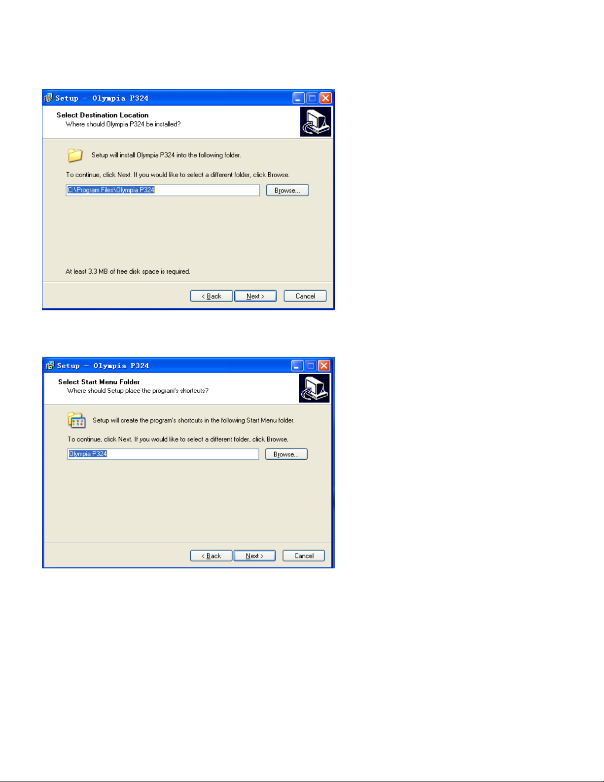
Installing the Software........................................................................................................................................................................... 4
P324 Programming Software............................................................................................................................................................ 4
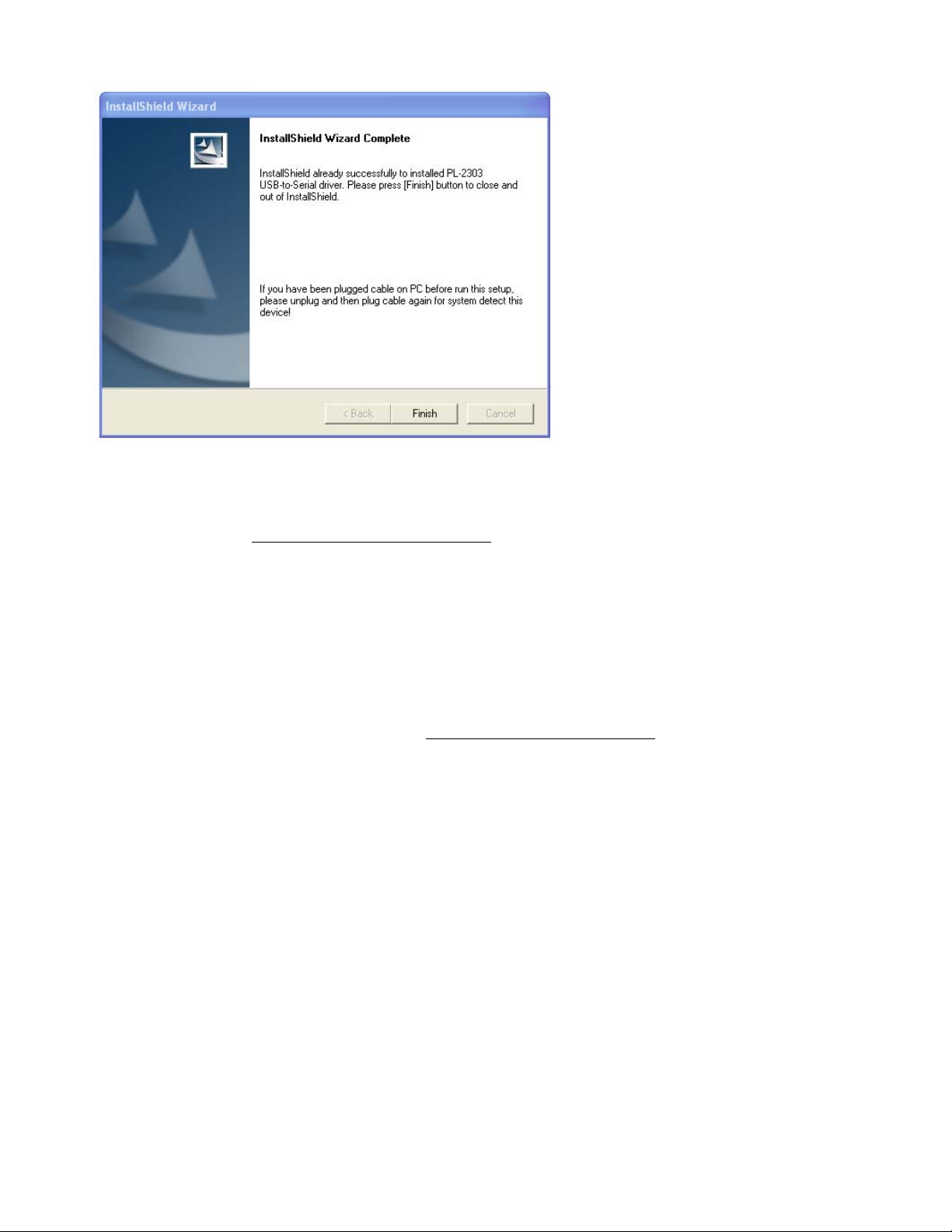
Notes on the USB Cable Driver........................................................................................................................................................ 5
How to Check the Driver Installation................................................................................................................................................. 5
Windows 2000, ME, and 98SE port reassignment ........................................................................................................................... 6
Uninstalling the Software...................................................................................................................................................................... 9
USB Cable Driver ............................................................................................................................................................................. 9
P324 Programming Software............................................................................................................................................................ 9
Software Operation............................................................................................................................................................................. 10
Initial Login In ................................................................................................................................................................................. 10
Changing your Account password ...................................................................................................................................................11
User Account Management .............................................................................................................................................................11
Communicating with the Radio........................................................................................................................................................... 13
Serial Port Settings......................................................................................................................................................................... 13
Reading data from the radio: .......................................................................................................................................................... 13
Writing data to the radio:................................................................................................................................................................. 14
File Management................................................................................................................................................................................ 15
Creating a new .bin file................................................................................................................................................................... 15
Saving settings to a .bin file............................................................................................................................................................ 15
Opening a saved .bin file................................................................................................................................................................ 15
Printing a .bin file............................................................................................................................................................................ 16
General Settings................................................................................................................................................................................. 17
Squelch Level Setting..................................................................................................................................................................... 17
Keypad Lock Setting....................................................................................................................................................................... 17
CTCSS Values:............................................................................................................................................................................... 17
Frequency/Channel display settings............................................................................................................................................... 18
Radio ID.......................................................................................................................................................................................... 18
Power Save.................................................................................................................................................................................... 18
Tones and Alerts ................................................................................................................................................................................. 19
Keypad Tone Setting....................................................................................................................................................................... 19
Setting Roger Beep ........................................................................................................................................................................ 19
Setting Low Battery Alert ................................................................................................................................................................ 19
Setting the transmitter Time Out Timer........................................................................................................................................... 19
Programming Memory Channels........................................................................................................................................................ 20
Manually entering a frequency........................................................................................................................................................ 20
Copy and Paste a complete Channel Setting................................................................................................................................. 20
Frequency Step settings................................................................................................................................................................. 20
CTCSS and CDCSS Settings......................................................................................................................................................... 21
Transmitter Power Level................................................................................................................................................................. 21
Band Setting................................................................................................................................................................................... 21
Busy Channel Lockout Setting........................................................................................................................................................ 22
Scan Setting................................................................................................................................................................................... 22
Priority Channel Setting.................................................................................................................................................................. 22
Emergency Call Key Settings ............................................................................................................................................................. 23
Enable Emergency Call mode........................................................................................................................................................ 23
Setting Emergency RX/TX timing values........................................................................................................................................ 23
Logout and Exit Program.................................................................................................................................................................... 24
Logout from a user account............................................................................................................................................................ 24
How to exit the PC programming software ..................................................................................................................................... 24

3
Introduction
This document will guide the user to install and operate the Olympia P324 PC programming software. The software can
set all programmable parameters of the radio, save a binary file for radio “cloning,” and organize files with settings for
various radio configurations.
PC Programming Kit Contents
The kit includes the following:
1 CD with:
OLYMPIA P324 Program
Programming User’s Guide
Radio User’s Guide
Examples of Memory Channel .bin files
1 RS-232 to P324 Radio programming cable
OR
1 USB to P324 Radio programming cable

4
Installing the Software
P324 Programming Software
Insert the CD in the appropriate drive. The installation should start automatically.
You may navigate to the CD drive and double click the Olympia P324 autorun.exe icon to start the installation
1. The welcome screen appears. Click 1> 2> or 3> as appropriate for your operating system to continue or click
Exit to terminate the installation.
2. The installation screen below appears. If you are using a USB cable, you will be installing the USB driver and
the Olympia P324 program in two stages.
Click Next to continue with USB setup.
If you are using a RS-232 cable, click Cancel to skip the USB installation and skip to step 4. below.

5
3. The installation complete screen below appears.
Click Finish to continue with the Olympia P324 setup.
Notes on the USB Cable Driver
The file USB DataCable Driver ReadMe.txt gives additional details on using the USB drivers on your
PC
1) Plug the Cable into a USB port.
2) The Welcome to the Found New Hardware Wizard or Add New Hardware Wizard (Win98)
should appear. If it does not appear, go to step 9.
3) Ensure the product driver CD (included with package) has been inserted in your CD-ROM
drive.
4) Select the option: Install the software automatically (Recommended) or Search for the
best driver for your device (Win98)
5) Press Next. Win 98 users should check CD-ROM drive.
6) Windows should find the Prolific USB-to-Serial Comm Port driver. Otherwise you should find
the directory under your version of Windows under the USB to RS232 1.1 directory on the
CD-ROM. Windows 98 lists the device as GM USB to Serial Bridge.
7) You will probably see a message indicating that the driver has not passed Windows Logo
testing. Press Continue Anyway. This warning can be safely ignored.
8) Press Finish when prompted by Windows to complete the installation.
9) *** If the Found New Hardware Wizard did not appear in step 2:
Open Device Manager by doing the following:
a)ClickonStart and then Control Panel.
b) Switch to Classic View (if in Category View).
c) Double click on System.
d) Select the Hardware tab.
e) Press the Device Manager button.
10) Under Ports (COM & LPT) look for a USB Device entry with a yellow exclamation point '!' by
it.
11) Right click on the USB Device and select Update Driver.
12) This should bring up the Welcome to the Hardware Update Wizard.
13) Ensure the product driver CD (included with package) is inserted in your CD-ROM drive.
14) Select the option: Install the software automatically (Recommended).
15) Press Next. Continue on step 5 above.
How to Check the Driver Installation
Windows XP, 2000, ME, and 98 include a function that allows you to reassign the COM port.

6
It is possible that the COM port number assigned is too high. Sometimes a device won't work with the
USB-to-Serial adapter even though everything appears to have installed correctly because some
computers will only scan a limited number of COM ports.
For instance, it is possible that a computer has a limitation of scanning only the first four COM ports.
If the adapter is installed on COM5, a device with such a limitation will not work until the COM port is
reassigned to COM1 - COM4.
Windows 2000, ME, and 98SE port reassignment
1) Go to the Device Manager:
Windows 2000/2003: Start -> Settings -> Control Panel -> System -> Hardware -> Device
Manager
Windows XP: Start -> Control Panel -> System -> Hardware -> Device Manager
2) Expand Ports (COM & LPT) in the list of devices
3) Right click on the Prolific USB to Serial Port and click on Properties
4) Click on the Port Settings tab. Click on the Resources tab.
5) Uncheck the box that says Use automatic settings.
6) Select Input/Output range. Click on Change Settings.
7) Type "02E8-02EF" in the Value box. This value will change the port to COM 4. If COM 4
is in use, you must choose another port. The values for each port are:
COM 1: 03F8-03FF
COM 2: 02F8-02FF
COM 3: 03E8-03EF
COM 4: 02E8-02EF
8) After entering the value, click OK. Click OK again and click Yes when the "Creating a
Forced Configuration" window appears. Click OK again.
9) Restart your computer. If you go into the device manager, you will see that the COM port
has changed to the one you have selected.
4. The Olympia P324 welcome screen appears. Click Next to continue or click Cancel to terminate the installation.

7
5. The folder where setup installs the files can be changed. The default directory is C:\Program Files\Olympia
P324. Click Browse… to change the directory, or click Next to continue using the default location.
6. 3. The name of the Start Menu folder can be changed. Click Browse… to change the directory, or click Next to
continue using the default folder name.

8
7. 4. Select whether to create a desktop icon or not. Click Next to continue.
8. 5. The install screen appears. Click Install to continue with the installation.
9. 6. Installation is completed. Click Finish to exit the program.

9
Uninstalling the Software
USB Cable Driver
Open Device Manager by doing the following:
1. Click on Start and then Control Panel.
2. Switch to Classic View (if in Category View).
3. Double click on System.
4. Select the Hardware tab.
5. Press the Device Manager button.
6. Under Ports (COM & LPT) look for a USB Device entry “Prolific USB-to-Serial Comm Port.”
7. Right click on the USB Device and select Uninstall.
8. Confirm Device Removal will appear. Click OK to uninstall.
P324 Programming Software
If you need to uninstall the software from the PC, uninstall from the program folder. Click Start then click All Programs
and click Olympia P324 Use the Uninstall Olympia P324 item to remove the software.
There will be a message box prompt to confirm the uninstall. Click Yes to continue and remove the software, or No to
cancel and leave the software installed.
After uninstalling the program, click OK to exit the wizard.

10
Software Operation
Initial Login In
When you finish the installation, double click the Olympia P324 icon to run the program.
A login screen will appear:
The default username is admin
The default password is 123456
Input the default user name and password, press [OK] to confirm, and the main screen will display:

11
Changing your Account password
1. On the Account menu click Change Password and the screen will display:
2. Input the Old password, and the New Password (twice, to confirm)
3. Click OK to confirm or Cancel to exit without changing.
User Account Management
User account permission level Admin enables all user management functionality. An Admin account user may
•Add a new user
•Edit an existing user
•Delete an existing user.
On the Account menu click User Management and the screen will display:
Exit User Management:
Click Exit to leave User Management and return to the main screen.

12
Adding a new user account:
1) Click Add to open the Add User box:
2) Input a Username for the new account.
3) Input a Password for the new account.
4) On the Permission pull down menu choose a level from the listed values:
Admin: All functionality is enabled.
User: User cannot perform User Management.
Factory: Can only read and write setting files created by User or Admin.
5) Click OK to save the new user account settings.
Edit a user account:
1) Click Edit to open the Edit User box
2) On the Permission pull down menu choose a level from the listed values.
3) Press OK to save the account settings, or Cancel to return previous screen.
Delete a user account:
1) Choose a account from the account list.
2) Click Delete the Notify screen will pop.
3) Press OK to confirm.

13
Communicating with the Radio
Serial Port Settings
Follow these steps to set up communication with the radio:
1. Turn off the radio to be programmed
2. Connect the RS-232 or USB cable between the radio and computer
3. On the Options menu click Serial Port Settings and the screen will display:
4. Select the correct COM port for your computer from the pull down menu.
5. Press OK to confirm the setting.
6. Turn on the radio to be programmed.
If the serial port settings and cable connections are correct, the icon will be updated to . Indicating the radio is
communicating properly with the programming SW. Data can be read from and written to the radio.
If the COM port is not correct, the cable is disconnected, or the radio is turned off, the icon will change to .
Indicating the radio is not communicating with the programming SW.
Note that non-standard RS-232 ports (and particularly USB to RS-232 adaptors) may not function. If the icon will
not change to after trying all COM port settings, a non-standard serial port or serial port adaptor is likely to be the
cause. See p. 5 Installing the Software USB Cable Driver to troubleshoot the port settings and drivers.
Reading data from the radio:
On the Program menu click Read (or click the button) and the screen will display
The current settings saved in the radio will be read and displayed on the main screen.

14
Factory Default (USA) settings are shown in the following image of the main screen:
Writing data to the radio:
On the Program menu click Write (or click the button) and the screen will display
The current settings displayed on the main screen will be written to the radio. The radio will then be reset – a power on
display sequence should be noted on the radio after successfully writing data.

15
File Management
All radio settings and memory contents can be saved in .bin files for later use. An entirely new file can be created and
written to a radio or saved. Aradio’s settings can be read, altered, saved, or written back to the radio. Multiple radios
can be cloned from an existing file or the contents of any desired radio.
Creating a new .bin file
On the File menu click New (or click the button) and the screen will open a blank main screen.
Saving settings to a .bin file
All settings on the main screen can be saved to a file on the computer.
On the File menu click Save (or click the button) and the screen will display
1. Select a folder for saving your P324 radio files
2. Under File name: enter the file name you want the settings to be saved to
3. Click Save to save the file on the computer
Opening a saved .bin file
A saved .bin file can be opened, altered (if necessary) and then written to the radio or saved for later use.
On the File menu click Open (or click the button) and the screen will display:

16
Navigate the folders and select the desired file, then click Open button.
Printing a .bin file
On the File menu click Print (or click the button) and the system print dialogue will display:
The complete contents of the main screen will be printed for reference.

17
General Settings
Squelch Level Setting
The adjustable Squelch allows you to optimize the receiver sensitivity. There are 5 levels of sensitivity.
On the Squelch Level drop down menu select a level from 1 to 5.The screen will display
Level 1 is the most sensitive level; the radio can receive the weakest signals.
Level 5 is the least sensitive level; the radio can only receive the strongest signals.
Squelch level can also be altered using the func key on the radio. Any altered setting will be read from the radio by
software (see How to read data from your radio)
Squelch can be opened manually with the mon key on the radio.
Keypad Lock Setting
This feature locks the radio from accidental changes.
On the Keypad Lock: dropdown menu click Enable or Disable. The screen will display
Keypad Lock can also be altered manually using the func key on the radio. The setting altered will thereafter be read
from the radio by software (see How to read data from your radio)
CTCSS Values:
CTCSS is supported by a standard set of 38 tone frequencies or an extended set of 50 (12 non-standard) tone
frequencies.
On the CTCSS Code: drop down menu select either 38 or 50.The screen will display
Either setting also allows for use of 83 standard CDCSS code words. Carrier level squelch is also supported.
Both CTCSS and CDCSS are disabled using the value 0.0 Hz (displayed on the radio LCD as 0.) Squelch then
operates on the sensed signal level only.
If a 38 tone set is selected, a code value will be displayed on the radio LCD as 0 to 121. If 50 is selected, the value is
displayed as 0 to 133.

18
Frequency/Channel display settings
The radio LCD can display either the current RX and TX frequency, or the Channel number value.
On the Display Option: dropdown menu click Channel or Frequency. The screen will display
Radio ID
Each radio will display a six digit Radio ID value at power on. Radio ID can be set to any six digit value between
000000 and 999999. Avalue entered with less than six digits will be displayed with leading zeros.
Power Save
The radios are designed with a power saving mode: If there is no activity on the channel or a button pressed on the radio
for 10 seconds the unit will enter power save mode. The receiver will alternately sleep and monitor the channel every
300 msec.
On the Keypad Lock: dropdown menu click Enable or Disable. The screen will display

19
Tones and Alerts
Keypad Tone Setting
If this feature is enabled, the radio speaker emits a tone each time a button is pressed.
On the Keypad Tone dropdown menu click Enable or Disable. The screen will display
Setting Roger Beep
If this feature is enabled, the radio transmits a unique tone each time PTT is released.
On the Roger Beep dropdown menu click Enable or Disable. The screen will display
Setting Low Battery Alert
When the battery charge state is low ( when the battery indicator displays one segment ) the unit chirps every 10
minutes. The radio will also chirp once each time the PTT key is released.
On the Low Battery Alert dropdown menu click Enable or Disable. The screen will display
Setting the transmitter Time Out Timer
The TX Time Out Timer limits how long the radio can transmit continuously. This feature limits excessively long or
undesired accidental transmissions to save battery life and limit channel interference. If PTT is held longer than the
value set, the radio will cease transmission of signals and sound a continuous warning tone from the speaker.
On the Time Out Timer drop down menu select a level from 30 to 300 seconds.The screen will display

20
Programming Memory Channels
32 channel memories can be programmed. The radio is operational from 406.2 MHz - 470MHz. Specific channel
frequencies depend on national regulations and vary by market. Some frequencies are blocked in software by FCC
requirement for the US market.
Factory default settings are on 2 FCC Itinerant channel frequencies. 5 channels are programmed for each frequency;
4 with CTCSS values and 1 with CTCSS off.
For each channel, the programmed RX Freq. and TX Freq. can be programmed to the same value (simplex mode) or to
different values (duplex frequency mode) to accommodate any repeater frequency offsets.
Any channels on the main screen with RX Freq. and TX Freq. fields empty will not be written to the radio. These
channels will be empty, and unused channels will not display on the radio.
Manually entering a frequency
The programmed RX and TX Frequencies must be an integer multiple of 6.25 kHz or 5kHz. Entering other values will
result in error messages when the frequency is written to the radio. Frequencies can be typed directly.
Copy and Paste a complete Channel Setting
Most common keyboard shortcuts ( Ctrl-C, Ctrl-V, Ctrl-X, arrows, Ctrl-arrow spacebar, etc.) are functional to navigate
on the main screen, cut, copy, paste, scroll up/down, and change values in drop down menus.
Click on a channel number in the left most column. The screen will highlight the entire row
All settings for Channel 10 can be copied and then pasted at another channel location. Similarly, only one frequency
value can be copied RX to TX, or channel to channel.
The Del key will clear a single frequency or drop down menu setting.
Frequency Step settings
On the Step drop down menu click 12.5 kHz, 20.0 kHz, or 25.0 kHz. The screen will display
To edit the values in RX Freq or TX Freq columns quickly, click in the desired cell so the vertical cursor bar appears.
Pressing the keyboard arrow keys will increment or decrement the frequency value by one Step setting increment:
>
Press and hold the arrow keys to rapidly scroll the frequency value up or down in increments of the Step setting.
Other manuals for Olympia P324
3
Table of contents
Other Olympia Radio manuals