Omax ProtoMax User manual

ProtoMAX®
Operation Guide
Lockout/Tagout
Implement standard practices and procedures to shut down equipment, isolate it
from its energy source(s), and prevent the release of potentially hazardous energy
while maintenance and servicing activities are being performed.
Equipment Grounding Requirements

•Ensure the equipment is properly grounded in accordance with national, state,
and local codes. Never remove any prong from the plug. Always plug into a
proper electrical outlet.
•To reduce the risk of electric shock, during a malfunction or breakdown,
grounding provides the electric current with a path of least resistance. The
machine is equipped with an electric cord designed with an equipment-
grounding conductor (EGC) and a grounding plug (United States, Canada and
Mexico only). You must plug the cord into a matching outlet that is properly
installed and grounded in accordance with all local codes and ordinances.
•Do not modify the plug provided—if it does not fit the outlet, have the proper
outlet installed by a qualified electrician.
•Connecting the EGC improperly can result in electric shock.
•Contact a qualified electrician or service personnel if you do not understand the
grounding instructions, or if in doubt as to whether the equipment is properly
grounded.
•Do not use extension cords with the equipment.
•If the cord is damaged or worn, immediately replace it. Contact OMAX for
replacement parts and instructions for replacement. The insulation of the EGC is
covered with a green or green with yellow-striped surface. If replacement of the
electric cord or plug is necessary, do not connect the equipment-grounding
conductor to a live terminal. Refer to the equipment-specific wiring
configuration.
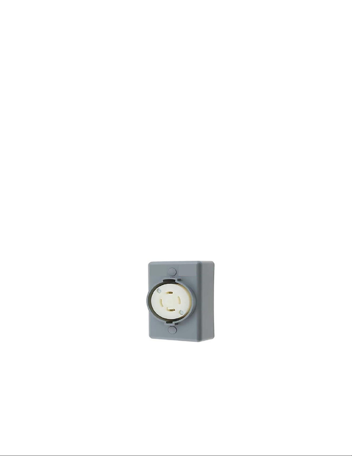
•The equipment is intended to be used on a circuit with an outlet similar to the
one shown (United States, Canada and Mexico only):
Figure 205
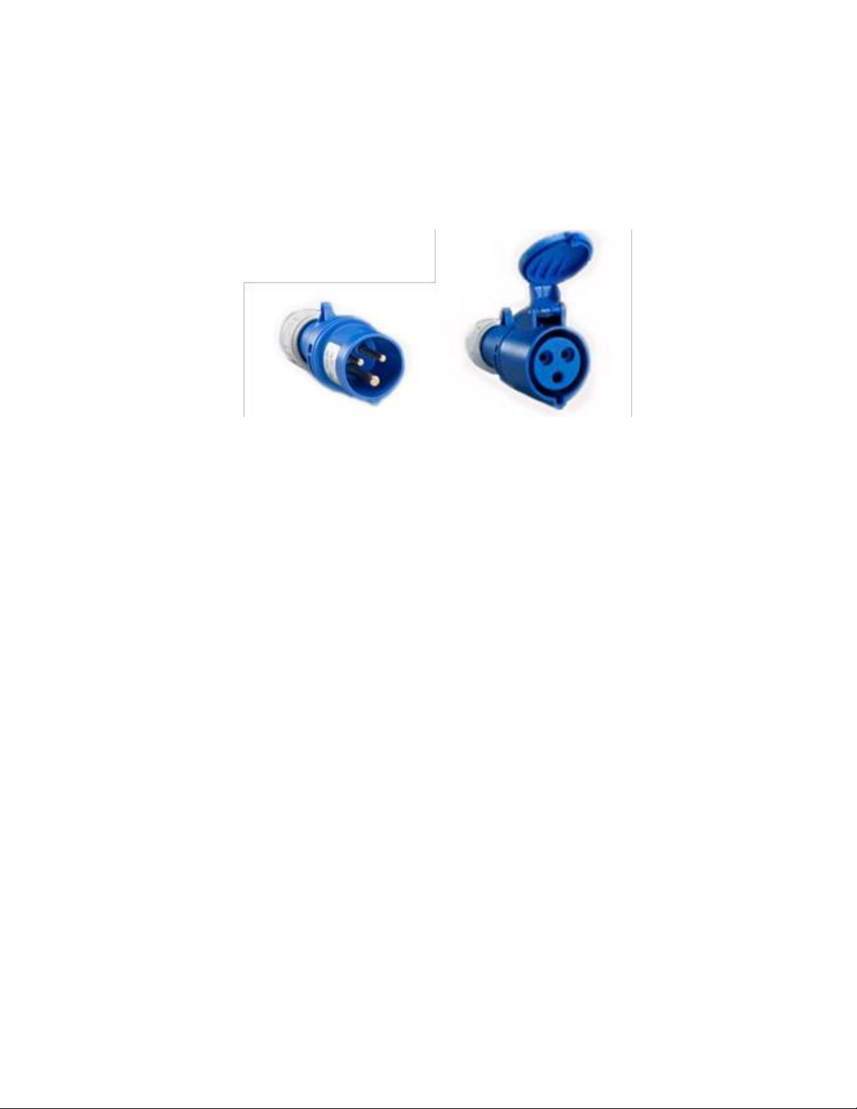
•The grounding plug is similar to the one shown (United States, Canada and
Mexico only):

Figure 206
•Ensure that the equipment is connected to an outlet that matches the plug
configuration.
•The equipment must not be connected to any different type of electric circuit.
•No adapter is available, or should be used with this equipment.
•For countries other than United States, Canada and Mexico; OMAX does not
supply a suitably rated industrial grade plug.
•Contact a qualified electrician or service personnel for installation of a suitably
rated industrial grade plug in accordance with national, state, and local codes.
•A pin and sleeve plug, rated at least 30A, 230V, 2-pole+E (3-wire
grounding), IP44 or better, having a first-make last-break protective bonding
contact (earthing contact) in accordance to standards IEC 60309-1 and IEC60309-
2 may fulfill this requirement.
Figure 207

•You must plug the cord into a matching outlet that is properly installed and
grounded in accordance with all local codes and ordinances.
Figure 208
Explosive Atmosphere Precautions
Machining certain types of material such as titanium with a waterjet may produce
sparks. Do not operate the equipment in an explosive atmosphere. Do not allow
explosive or flammable vapors to accumulate in the area of the equipment.
Equipment Safety Features
The abrasive waterjet provides several built-in safety features:
Overpressure Protection
During operation, pump pressure is monitored to prevent an overpressure
condition. If the pump exceeds the factory set maximum pressure limit, the safety
relief valve activates and shuts down the pump unit.
Electrical Protection
The equipment controller includes short circuit, over current and thermal protection
for the pump motor.
Electrical Disconnect/Emergency Machine Off (EMO)
An electrical disconnects/emergency machine off (EMO) switch is used to remove
the main AC electrical supply from the machine. To isolate the machine from its
electrical supply, always unplug the main AC supply power cord from its electrical
supply outlet.
Safety Lid
The lid of the equipment is designed with a safety interlock to prevent waterjet
operation when the lid is open.

Safety Legend
The following safety signal-word panels and paragraph notifications may appear
throughout this and other documentation. Each provides safety-issue identification
and recommended actions to avoid the hazard. Be alert! Follow the recommended
safety actions and precautions to prevent injury or damage to the equipment.
WARNING
Indicates a hazardous situation which, if not avoided, could result in death or
serious injury.
CAUTION
Indicates a hazardous situation which, if not avoided, could result in minor or
moderate injury.
NOTICE
Used to address practices not related to physical injury ─property damage only.
NOTE:
Used to provide supplementary information, emphasize a point or give a tip for easier
operation.
Required Tools
The following table contains a list of tools with the appropriate sizes needed when
operating the ProtoMAX.
Customer Provided Tools
These tools are not provided by OMAX or included with the ProtoMAX.
Icon
Tool
Size(s)
Torque wrench
15–102 in-lb (2–12 Nm)
Hex socket
4 mm
Shop towels
Allen wrench
4 mm
Open-end wrench
19 mm
Crowfoot wrench
19 mm
OMAX Provided Tools
The following table contains a list of tools provided by OMAX that are needed to
operate the ProtoMAX. Tools listed with part numbers are included with

the ProtoMAX or are available for purchase. Contact technical support for more
information.
Icon
Tool
Size(s)
Stand-off tool
(P/N 317876)
Technical Specifications
See ProtoMAX Utilities Requirements for the technical specifications.
Introduction
This guide provides information and instructions to operate the abrasive waterjet
cutting system. It explains how the pump and abrasive waterjet system work. It also
provides instructions on how to machine a part, how to start and stop the system, and
how the software (Intelli-MAX® Proto) is used to machine a part.
Abrasive Waterjet Overview
The ProtoMAX abrasive waterjet is a precision machining tool that operates under
software control using high-pressure water and garnet abrasive to cut complex parts
out of most materials including metal, plastic, glass, ceramics, stone and composites
using standard CAD drawing files.
Components
The ProtoMAX takes up little shop floor space. The cutting stage has a 12 in. (30 cm)
(X-axis) by 12 in. (30 cm) (Y-axis) cutting area with an easy material alignment system
for cutting parts. The precision drive components are protected inside sealed bellows
from water and garnet abrasive. The manual Z-axis allows cutting of materials up to 1
in. (3 cm) thick. The cutting area is fully enclosed by a see-through enclosure
supporting a safety interlock system to halt abrasive waterjet cutting when opened.
The ProtoMAX consist of the following major components:

Figure 209
1] Table assembly
[2] High-pressure pump
Table Assembly
The ProtoMAX table assembly is comprised of the cutting stage, garnet abrasive
delivery system, catcher tank, electrical control enclosure, water filter, and operator
controls.
Figure 210

[1] Garnet abrasive delivery system
[4] Electrical control enclosure
[2] Cutting stage and X, Y, and Z stage
[5] High-pressure plumbing
[3] Catcher Tank
[6] Power and water controls
Cutting Stage Lid and Side Panels
NOTICE
Do not remove the side panels under normal conditions. Damage may occur when
operating the ProtoMAX with the side panels removed. Only remove them when
required by maintenance or troubleshooting procedures.
The cutting stage lid provides safe access to view the cutting process. The lid has a
built in safety interlock switch that halts all cutting operations (pauses MAKE, stops
stage motion, and turns off the pump) when the lid is opened. Always use the Pause
button in the software to pause the system before opening the lid. This allows the
operator to safely inspect the work and adjust materials as needed. Once the lid is
closed, the cutting operation may be continued. Side panels provide protection to
the catcher tank and pump. Incoming water pressure may be monitored through the
viewing portal located on the right side panel. Panels should remain on the table
assembly during operation. Panels can be easily removed for access to the interior
components.
Figure 211
[1] Cutting stage lid
[2] Side panel (x 3)
X, Y, and Z-axis Cutting Stage
The cutting stage provides a 12 in. (30 cm) (X-axis) by 12 in. (30 cm) (Y-axis) cutting
envelope. The Z-axis allows manual up and down movements for cutting materials
up to 1 in. (3 cm) thick.

The cutting stage uses the same grid and coordinate system as in the Intelli-
MAX software. When looking down on the table, the X-axis runs left to right and the
Y-axis runs front to back. The Z-axis allows vertical movement of the cutting head.
When the ProtoMAX is homed, the nozzle is moved to the position X=0 and Y=0
coordinate at the lower left corner of the cutting envelope.
Figure 212
[1] X-axis
[2] Y-axis
[3] Z-axis
Slat Bed
The cutting stage has a removable slat bed assembly to support cutting materials.
The slat bed assembly is removed to access the cutting tank for cleaning and
maintenance. The slat bed assembly is secured to the cutting stage frame and
provides support for the part being machined.
Figure 213
[1] Mounting plate, rear
[3] Mounting plate, front
[5] Square fixture plate
[2] Slats
[4] Slat comb bracket (x 2)
[6] Slat comb (x 2)
Catcher Tank

The catcher tank stores the water from the cutting nozzle and provides a settling
tank for the spent garnet abrasive and cut away material. The catcher tank bottom is
shielded to prevent cutting through when operating the machine.
NOTICE
Do not add chemicals to the catcher tank water. Damage to the catcher tank and
other components may occur.
Figure 214
[1] Catcher tank
Tank Drain
The adjustable tank drain helps maintain optimal water level by allowing excess
water to drain from the catcher tank during cutting operations. The drain has a
flexible tube to adjust the water level as needed and allows cutting underwater. The
tank overflow allows excess water to exit through the drain port and drain hose to
prevent overfilling.
Figure 215
[1] Adjustable tank drain
[2] Tank overflow drain
[3] Tank drain hose
Material Holding System
The material holding system fixtures (secures) materials while machining a part.
Fixturing prevents the material from moving, vibrating, floating, tipping, or falling
into the tank. The abrasive jet stream is very powerful. The force exerted from the
abrasive waterjet stream into the tank can move or float the material during the

cutting process. If the material moves during machining, the part will not be precise
and may be ruined.
NOTE:
See the help files for best practices tips on fixturing materials.
Figure 216
[1] Holding arm, short
[3] Holding post
[3] Holding arm, long
Power Switch
AC power is controlled by a power switch located on the electrical control enclosure.
All ProtoMAX system power is removed when OFF.
Figure 217
[1] Power ON position
[2] Power selector
[3] Power OFF
position
Garnet Abrasive Delivery System
The garnet abrasive delivery system consists of the high-pressure nozzle, garnet
abrasive feed system (hopper and feed tube), and high-pressure plumbing. The
garnet abrasive hopper lid keeps the garnet abrasive from being contaminated with
debris or getting wet. The garnet abrasive screen helps to filter small pieces of debris
when filling the hopper that may clog the feed tube or nozzle. When machining a
part, the garnet abrasive flows from the hopper to the abrasive waterjet nozzle
through the garnet abrasive feed tube.

NOTICE
The garnet abrasive material in the hopper must be kept clean and dry. If moisture
enters the hopper, the garnet abrasive material will clump and clog the feed tube,
which will require cleaning. Even very small particles of dirt will clog the mixing
tube. Always store the garnet abrasive material in a covered, dry location protected
from metal chips and other debris.
Figure 218
[1] Hopper lid
[3] Abrasive feed tube*
[5] Hopper splash guard
[7] Garnet abrasive hopper assembly
[2] Garnet abrasive screen
[4] Abrasive feed block
[6] Hopper support plate
[8] Bulk abrasive port
* Tube routing is for illustration purposes only.
NOTE:
Always use garnet abrasive purchased from OMAX. This high-quality abrasive is more
consistent in particle size and contains less dust. Inconsistency in particle size makes it
difficult to maintain quality when cutting and increases the likelihood of the mixing tube
becoming clogged. When dust is present, static electrical charges can build up, causing the
garnet abrasive particles to clump together, hindering the garnet abrasive flow.
Abrasive Waterjet Nozzle
The abrasive waterjet nozzle contains a 0.030 in. (0.762 mm) replaceable mixing tube,
0.008 in. (0.2032 mm) replaceable (drop-in) orifice assembly, and nozzle body. High-
pressure water is forced through the orifice and enters into a larger mixing chamber,
drawing the garnet abrasive from the abrasive feed tube. The water and garnet

abrasive is mixed into high-speed slurry, and then moves into the mixing tube to
form the abrasive waterjet stream. The abrasive waterjet stream exits the mixing tube
through the bottom of the nozzle to strike and remove the material being machined.
Figure 219
[1] Nozzle inlet body assembly
[4] Garnet abrasive inlet
[7] Mixing tube retainer
[2] Inlet body weep hole
[5] Nozzle body assembly
[8] Mixing chamber
[3] Nozzle filter
[6] Mixing tube
[9] Orifice assembly
High-pressure Pump
The high-pressure pump provides approximately 30,000 pounds per square inch
(psi) of cutting pressure for the ProtoMAX. Output high-pressure from the pump is
automatically controlled by a variable frequency drive (VFD). The software helps
prevent damage to the pump by halting operation when there is inadequate
incoming water pressure, excess water temperature, or overpressure events.

Figure 220
[1] Crankcase
[6] High-pressure water transducer
[2] High pressure wet-end
[7] High-pressure water OUT connection
[3] Safety valve
[8] Cooling line OUT connection
[4] Cooling line IN connection
[9] High-pressure nipple support bracket
[5] Water IN connection
[10] Electrical connection
Water Filter
The water filter removes debris from incoming water that can clog and damage the
high-pressure components. The water filter is mounted on the side of the table
assembly. The outlet water pressure is monitored by the pressure gauge mounted on
the water filter.
NOTICE
Do not operate the ProtoMAX without the incoming water supply filter. Operating
the ProtoMAX without the water supply filter will introduce debris into the system
and may damage the pump and high-pressure system.
Figure 221
[1] Water manifold
[4] Water control solenoid
[7] Water temperature transducer

[2] Air release button
[5] Water pressure switch
[8] Water connection (incoming)
[3] Water pressure gauge
[6] Water filter assembly
Laptop
The ProtoMAX laptop is pre-installed with Intelli-MAX software and is connected to
the ProtoMAX by a USB cable.
Figure 222
Intelli-MAX® Proto Software
Intelli-MAX software by OMAX is easy-to-use and maximizes the functionality of
the ProtoMAX Abrasive Waterjet.
LAYOUT is computer aided design (CAD) software that creates tool paths for
the ProtoMAX abrasive waterjet system. LAYOUT includes all the basic commands
expected in a CAD package, as well as tools specific to abrasive waterjet machining.
The LAYOUT help system provides information needed to
operate LAYOUT's functions.
MAKE software controls the ProtoMAX abrasive waterjet system by sending precise
motor control commands to move the nozzle along a part's cutting path, while
controlling the high-pressure water. The MAKE help system provides information
needed to operate the software's cutting functions.
See the ProtoMAX Help system for more information on LAYOUT and MAKE.
Accessories
Optional accessories for the ProtoMAX can be found at www.protomax.com.
Make a Part Overview
Intelli-MAX LAYOUT and MAKE are the software tools used in making a part.
Following the below listed steps provides the process for successfully making a part.
Seehttps://knowledgebase.omax.com for detailed information on making a part.
LAYOUT
1. Import or create a drawing file (DXF file).
The first step in making a part is to obtain or create a drawing
file. LAYOUT software provides tools to create and edit new and existing

drawing files (.dxf) for machining. Drawing files may also be imported from
other CAD programs.
2. Assign machining qualities (edge finish).
The next step is to assign machining qualities (edge finish) to the drawing entities
(lines, arcs, etc.) that tell the nozzle how fast or slow to move to obtain the
desired edge finish.
3. Clean the drawing.
Next, the drawing should be cleaned to remove duplicate entities, extra dots,
gaps, and other garbage entities that are hard to find in the drawing. A clean
drawing eliminates machining confusion by defining only one continuous path
for the machine to follow.
4. Add path elements to the drawing.
After cleaning, path elements need to be drawn. Path elements tell the machine
where to cut, where to travel without cutting (traverse), when to pierce the
material (lead in) and the exit points (lead out).
5. Create the machine tool path file (ORD/OMX).
The last step in LAYOUT is to convert the drawing file to a machine tool path file
(ORD/OMX) that tells the machine how to cut the part.
MAKE
6. Start up the machine.
After the drawing file is prepared and converted to a machine tool path file, the
next step is to start the machine per the Startup Checklist.
7. Open and configure the ORD/OMX file.
The tool path file is opened and the material setup data is entered so the machine
knows the path to cut and the material type and thickness.
8. Load and secure the material.
The material is then placed and secured to the cutting stage. Fixturing the
material to prevent any movement in the X, Y, or Z directions is critical in
making good parts.
9. Position the nozzle
Attach the splash guard to the nozzle assembly with the cup up. Set the nozzle
stand-off at the highest point of the material surface, and then move the nozzle to
the start of the machine tool path.
10. Prepare for machining.
Conduct a dry run to ensure the part fits on the material and the nozzle clears
any obstacle. Any problems found during the dry run can be corrected before
machining the part.

Operate the ProtoMAX
See the Intelli-MAX® Help system for additional information on
using LAYOUT and MAKE software.
Startup Checklist
Startup Overview
The following checklist is a quick reference to ensure equipment startup tasks are
completed in the required sequence. Detailed instructions are located in Start
the ProtoMAX.
Turn ON the laptop (do not open the MAKE application)
Connect the USB cable to the laptop
Turn ON the main power; verify the light comes on
Turn ON the water supply
Check the water pressure
Open the MAKE application
Home the machine
Conduct a nozzle test without abrasive
Fill the hopper with garnet abrasive
Conduct a nozzle test with abrasive
Verify the garnet abrasive is flowing from the hopper to the nozzle
Inspect the visible high-pressure plumbing connections for leaks
Open and configure a kerf check sample file or the part to cut
Load and secure the material on the cutting stage
Set the nozzle stand-off
Position the nozzle at path start point
Perform a dry run
Fold down the splash guard cup
Add water to raise the water level above the material surface, adjust the drain height if
needed
Begin machining the part
Check the cutting water pressure
Adjust the tool offset if needed
NOTE:
A kerf check is performed only to verify mixing tube wear and to adjust the tool offset if
needed.
Start the ProtoMAX

Startup Overview
1. Turn ON the laptop power.
NOTE:
Do not open MAKE. The ProtoMAX USB cable must be plugged in and recognized by the
laptop before opening the MAKE program.
2. Connect the ProtoMAX USB cable [1] to the laptop.
Figure 223
3. Turn ON the main power [2] and verify the light [1] is on.
Figure 224
4. Turn ON the incoming water supply.
5. Record the incoming water pressure (Figure 225).
NOTE:
The incoming water pressure should be 45–85 psi.

6. Open the MAKE software.
7. Click the Machine needs to be homed banner to home the machine.
NOTE:
Home is required after every power cycle. For example, when the main power switch is
turned OFF and then turned back ON, during power outages, or the main power cord is
disconnected.
Figure 226
8. Conduct a nozzle test without abrasive.
a. Open and secure the lid.
CAUTION
Use care when opening or closing the lid to avoid injury. Keep hand, fingers, or
body part away from the side of the table when closing the lid. Never let the lid
free-fall.

Figure 227
b. Remove the abrasive feed tube from the nozzle and place it over the top of
the Y-axis [1].
Figure 228
c. Verify the mixing tube is properly seated and secured in the nozzle body.
Figure 229
d. Place the nozzle splash guard [1] on the mixing tube [2] with the cup folded
up.
Figure 230
Other manuals for ProtoMax
2
Table of contents
Other Omax Cutter manuals
Popular Cutter manuals by other brands

Holmatro
Holmatro SMC 4006 Maintenance instructions

Diamond Products
Diamond Products CC3538JK Series Operator's manual

Marshalltown
Marshalltown Bullet SharpShooter 2.0 manual

Double E
Double E M70 User and maintenance manual

ABC Office
ABC Office 1071 owner's manual

STAUFF
STAUFF SPR-PRC-POC operating instructions