OMEGA AIR RDL 35 User manual

Installation and operating
manual
Please read the following instructions carefully before installing the product. Trouble free and
safe operating of the product can only be guaranteed if recommendations and conditions stated
in this manual are respected.
20220929
Refrigeration Dryer Series RDL 35 - 235

2
20220929
Dear customer!
Thank you for purchasing our product. In order for the product to serve well and reliably, please read
these installation and operating instructions carefully.
In order to avoid misuse of equipment and potential hazards for the operator, please read thoroughly
and strictly follow the instructions contained in this installation and operating manual.
Before packing and shipping, each unit of the RDL refrigeration air dryers is subjected to rigorous tests
to ensure that the factory defects are removed and all the functions of the device for which it was
designed checked.
After correctly installing the unit in accordance with the instructions in this manual, it will be ready for
use without the need for additional settings. The operation is fully automated, and maintenance is
limited to a few checks and cleanings, as shown in the continuation of this manual.
These instructions must always be present at the unit and be available for the entire operating life
of the device. The instructions are considered as an integral part of each refrigeration air dryer.
This manual provides the user, installer and maintenance technician with all the technical information
needed to install, operate and perform routine maintenance work to ensure long service life. If spare
parts are required, they must be original. Requests for SPARE PARTS and any information relating to
the unit must be sent to the distributor or to the nearest service canter, indicating the MODEL and
SERIAL NUMBER located on the data plate of the device.
Due to uninterrupted technical development, we reserve the right to introduce the necessary changes
without prior notice. If you need further explanation or clarification, contact the manufacturer or
distributor of the device.

3
20220929
Table of Contents
1 GENERAL INFORMATION ............................................................................................................................... 4
1.1. DEVICE INFORMATION ....................................................................................................................................... 4
1.2. INFORMATION ON THE SUPPLIER.......................................................................................................................... 4
1.3 BASIC.............................................................................................................................................................. 5
1.4. REFRIGERATION AIR DRYERS................................................................................................................................ 5
1.5 PROPER USE ..................................................................................................................................................... 5
2 SAFETY INSTRUCTIONS..................................................................................................................................6
3 TECHNICAL SPECIFICATIONS .......................................................................................................................... 8
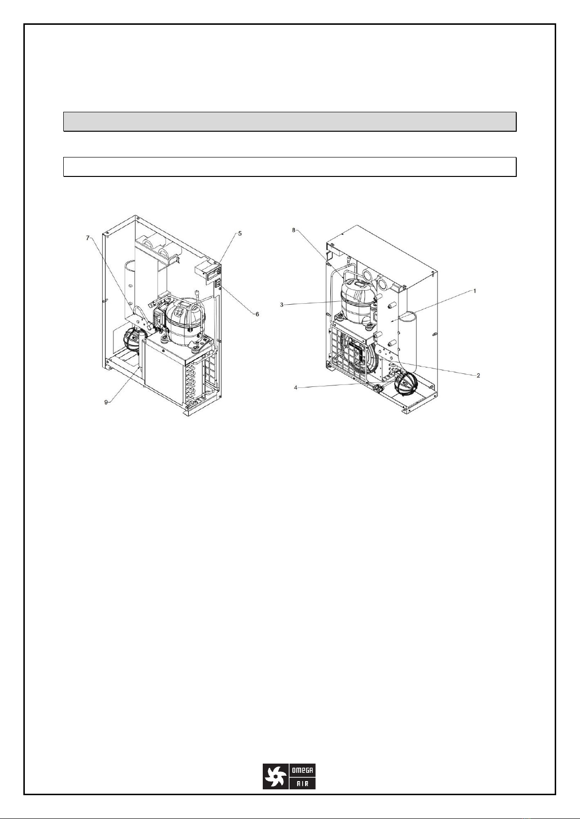
3.1 COMPONENTS................................................................................................................................................... 8
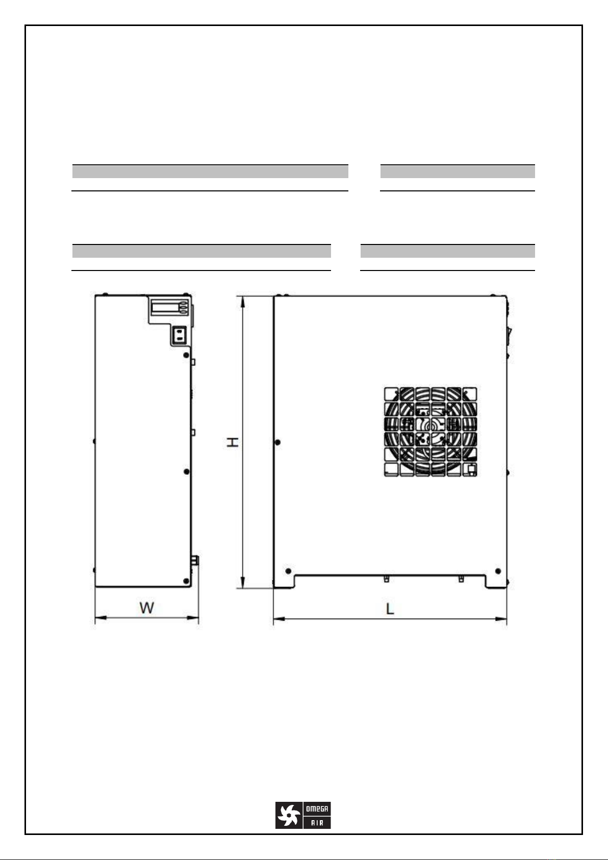
3.2 SPECIFICATIONS................................................................................................................................................. 9
4 REFRIGERATION AIR DRYER OPERATION ..................................................................................................... 11
5 REFRIGERATION AIR DRYER COMPONENTS ................................................................................................. 12
5.1 COMPRESSOR ................................................................................................................................................. 12
5.2 CONDENSER ................................................................................................................................................... 12
5.3. HEAT EXCHANGER 3IN1 ................................................................................................................................... 12
5.4 CONTROLLER RDC 3 ........................................................................................................................................ 13
5.4.1 ELECTRIC SCHEME RDC 3............................................................................................................................... 14
5.4.2 RDC 3PARAMETERS ..................................................................................................................................... 15
5.4.3 RDC 3MODBUS COMMUNICATION............................................................................................................... 17
5.6. AUTOMATIC MECHANICAL CONDENSATE DRAIN..................................................................................................... 18
5.7 SAFETY FUNCTIONS .......................................................................................................................................... 18
5.7.1 SAFETY FUNCTIONS OF RDC 3......................................................................................................................... 18
5.8 FILTER /DEHYDRATOR ...................................................................................................................................... 18
5.9 CAPILLARY TUBE .............................................................................................................................................. 19
6 EFFICIENCY .................................................................................................................................................. 19
7 TRANSPORT................................................................................................................................................. 19
8 STORING...................................................................................................................................................... 20
9 INSTALLATION ............................................................................................................................................. 20
9.1 GENERAL REQUIREMENTS FOR INSTALLATION ........................................................................................................ 20
9.2 INSTALLATION POSITIONING............................................................................................................................... 21
9.3. INSTALLATION PROCEDURE ............................................................................................................................... 22
10 START-UP .................................................................................................................................................. 23
10.1 BEFORE START-UP.......................................................................................................................................... 23
10.2 START-UP..................................................................................................................................................... 23
11 REMOVE FROM USE .................................................................................................................................. 23
12 MAINTENANCE .......................................................................................................................................... 24
13 TROUBLESHOOTING TECHNICAL PROBLEMS.............................................................................................. 24
14 SPARE PARTS............................................................................................................................................. 26
15 WARRANTY ............................................................................................................................................... 27
16 MAINTENANCE NOTEBOOKS ..................................................................................................................... 28
17 DRAWINGS OF RDL REFRIGERATION AIR DRYERS ...................................................................................... 30
18 ELECTRO SCHEMES OF RDL REFRIGERATION AIR DRYER ............................................................................ 32

4
20220929
1 General information
1.1. Device information
Please fill in the fields carefully. Correct data enables proper and efficient maintenance of the device,
selection of suitable spare parts and technical support.
1.2. Information on the supplier
Model of refrigeration air dryer:
Serial number:
Year of manufacture:
Date of installation:
Name:
Address:
Phone / Fax:
e-mail:

5
20220929
1.3 Basic
Compressed air contains contaminants such as water, oil and particles. Impurities need to be removed
or their concentration reduced to an acceptable level according to the requirements of the application.
The ISO 8573-1 standard specifies the purity / quality of the air for contaminants. The humidity (water
vapor content) can be expressed in terms of Pressure Dew Point (PDP). Dew point is the temperature
at which the air is 100% saturated with moisture. When the air temperature falls below the dew point,
moisture condenses. Reduction of moisture content to the point of dew point +3°C can be achieved by
refrigeration air dryers.
1.4. Refrigeration air dryers
Refrigeration air dryers are the best choice in all standard applications, where pressure dew point
3-10 °C suffices. Examples of such applications are process air in the processing industry (pneumatic
equipment, wood industry, paint shop, chemical industry, pharmacy, etc.).
1.5 Proper use
⚠RDL refrigeration air dryers are designed for efficient and quality preparation of dry compressed
air. This device must only be used for the purposes for which it was designed. All other uses of the
device are considered incorrect.
⚠The manufacturer is not liable under any circumstances for damage resulting from improper,
incorrect or unreasonable use of the device.
⚠Only use genuine spare parts. Warranty or Reclamation cannot be claimed for damage or
malfunction of the device caused by the use of non-original parts.

6
20220929
2 Safety instructions
⚠Improper use of the compressed air system and electrical installations can lead to injury or death.
⚠Improper handling (transport, installation, use, maintenance) of a refrigeration air dryer can lead
to serious injury or death. The result of improper use may be damage to the device and/or reduced
efficiency of the dryer.
⚠When operating the dryer, you must follow all relevant safety and accident prevention instructions,
all regulations and instructions for use. The RDL refrigeration air dryer was developed in accordance
with the generally recognized rules of engineering practice.
⚠Ensure that the installation complies with local legislation.
⚠The user or operator of the refrigeration air dryer must be familiar with the installation,
commissioning and operation of the appliance.
⚠All safety information is intended to ensure your personal safety. If you do not have experience
with such systems, contact the manufacturer or local supplier for technical assistance.
⚠Before working on the dryer, ensure that the dryer is vented and not under pressure (this also
includes the closest components of the installation in front and behind the dryer) and that the dryer
is not connected to an electrical source.
⚠Do not exceed the maximum operating pressure or operating temperature (information on the
data label).
⚠The permissible operating temperatures and working pressures for the accessories of the
adsorption dryer are given in the technical documentation of this accessory. The maximum
temperature and pressure of the assembled system is the lowest maximum temperature or pressure
of any individual part of the system.
⚠Ensure that the refrigeration air dryer is not subject to vibrations that can cause fatigue and
cracking of material.
⚠The refrigeration air dryer must not be subjected to mechanical stress.
⚠All installation and maintenance work on the refrigeration air dryer can only be carried out by a
qualified and experienced specialist.
⚠It is forbidden to make any changes to the refrigeration air dryer.
⚠Vent the refrigeration air dryer system before performing any kind of installation or maintenance
work.
⚠Ensure that the refrigeration air dryer is installed in accordance with specifications and without
mechanical loads.

7
20220929
⚠Only use genuine spare parts.
⚠Only use refrigeration air dryers for intended purpose.
⚠When transporting the dryer, check and follow the local regulations for lifting and transporting
heavy objects.
⚠In the event of fire, do not use extinguishing water on the dryer and nearby objects.
⚠Wear suitable protective equipment: ear plugs, safety goggles, safety helmet, safety gloves and
safety shoes.
Figure 1: Location of the data plate

8
20220929
3 Technical Specifications
3.1 Components
1. Heat exchanger 3in1
6. Main power switch
2. Condenser
7. Capillary tube
3. Compressor
8. Temperature sensor
4. Condensate drain
9. Filter / dehydrator
5. Controller
Figure 2: Components (shown: RDL 235)

9
20220929
3.2 Specifications
TECHNICAL SPECIFICATIONS
Max. operating pressure
13 barg
Max. inlet air temperature
55 °C (for temperature ≠ 35 °C apply correction factor)
Operating ambient temperature
1,5 °C to 45 °C (for temperature > 25 °C apply correction factor)
Max. storage temperature
65 °C
Pressure dew point
+ 5 °C
Filter requirement (inlet)
Prefilter 3 μm
Communication
MODBUS
Digital input
Remote ON/OFF
Digital output
Alarm
Type of cooling
Air cooled
Refrigerant
R134a
Compressor operation
Non-cycling
Condensate drain
AOK 13PA
Power supply
1Ph, 230 V, 50/60 Hz
Protection class (controller front)
IP 20
MATERIALS
Casing
Carbon steel
Casing corrosion protection
Epoxy powder painted
Evaporator
Aluminium
Evaporator insulation
Flexible elastomeric foam
Condenser
Copper tube, aluminium fins
Compressor
Carbon steel
Refrigerant piping
Copper
Controller enclosure
Plastic
SIZES
Compressed air
Electrical connection
Ambient air
Refrigerant
Dimensions & Mass
Model
(3)Flow
Connection
Pressure
drop
Power supply
(4)Power/
Consumption
Cooling
flow
Heat
rejec.
Type
Mass
W x L x H
Net
m3/h
bar
Ph~V-Hz
kW
m3/h
kW
kg
mm
kg
RDL 35
35
G 1/2” BSP-F
<0,2
1~230-50*
0,17 / 0,13
250
0,3
R134a
0,230
220 x 532 x 665
23
RDL 75
75
G 3/4” BSP-F
<0,2
1~230-50/230-60
0,40 / 0,25
250
0,6
R134a
0,380
220 x 532 x 665
24
RDL 100
100
G 1” BSP-F
<0,2
1~230-50/230-60
0,43 / 0,29
250
0,8
R134a
0,585
220 x 532 x 665
30
RDL 180
180
G 1” BSP-F
<0,2
1~230-50/230-60
0,52 / 0,37
700
1,5
R134a
0,71
220 x 573 x 763
46
RDL 235
235
G 1 1/2” BSP-F
<0,2
1~230-50*
0,61 / 0,46
700
1,9
R134a
0,89
220 x 573 x 763
49
(3) Nominal conditions: inlet flow 20 °C at 1 bara, ambient 25 °C, dryer inlet 35°C at 7 barg, 5 °C pressure dew point (-19,3 °C atmospheric).
(4) For 60 Hz 20 % more than stated, consumption at nominal conditions.
* Special 60 Hz version available.

10
20220929
CORRECTION FACTORS
To calculate the correct capacity of a given dryer based on actual operating conditions, multiply the nominal
inlet flow by the appropriate correction factor(s). CORRECTED CAPACITY = NOMINAL FLOW CAPACITY x COP x
CAT x CIN x CDP
OPERATING PRESSURE DEW POINT
[bar]
4
5
6
7
8
10
12
13
°C
3
5
7
10
[psi]
58
72
87
100
115
145
174
189
°F
37,4
41
44,6
50
COP
0,77
0,86
0,93
1
1,05
1,14
1,21
1,24
CDP
0,9
1,0
1,1
1,26
INLET TEMPERATURE AMBIENT TEMPERATURE
[bar]
25
30
35
40
45
50
55
°C
25
30
35
40
45
[psi]
77
86
95
104
113
122
131
°F
77
86
95
104
113
COP
1.2
1,12
1
0,83
0,69
0,59
0,5
CDP
1
0,96
0,9
0,82
0,72

11
20220929
4 Refrigeration air dryer operation
The refrigeration air dryer is designed to remove moisture from the input air to achieve the desired
dew point at the exit.
All refrigeration air dryers described above operate according to the same principle. The operation of
the refrigeration air dryer can be divided into two main circuits: Air and refrigeration circuit.
Air Circuit: Hot, moisture saturated air enters the 3in1 heat exchanger. The air then passes through
the evaporator, also called the air / refrigerant heat exchanger. The air temperature is reduced to
about 2 ° C, which causes condensation of the water vapor. The liquid is merged into larger droplets
and collected in a separator, from where the condensate drain removes it from the system. The cool
air without liquid water is returned through the air / air heat exchanger, where it is heated to
approximately 5 ° C lower temperature than the input air.
Refrigeration circuit: The refrigerant enters the compressor and then enters the condenser at high
pressure, where it transfers heat to the ambient air and condenses. The liquid then passes through the
capillary tube, where its pressure and consequently the temperature decreases. At low pressure, the
liquid refrigerant enters the heat exchanger where it receives heat from the inlet compressed air and
causes the evaporation of the refrigerant. The low-pressure gaseous refrigerant returns to the
compressor, which compresses it and starts the cycle again
* For more detailed information contact your supplier.
1Heat exchanger 3in1
a Air / air heat exchanger
b Air / coolant heat exchanger
c Separator
2Inlet of compressed air
3Outlet of compressed air
4Compressor
5Condenser
6Filter / Dehydrator
7Capillary tube/Thermal expansion
valve
8Condensate drain

12
20220929
5 Refrigeration air dryer components
5.1 Compressor
The compressor sucks the gaseous phase of the refrigerant from the evaporator (low pressure side)
and compresses it to the condensation pressure (high pressure side). Built-in compressors are
manufactured by leading manufacturers and are designed for applications where high compression
ratios and high temperature differences are present. Hermetically sealed structure is tight and
provides high energy efficiency and long service life. The anti-vibration springs that carry the
compressor reduce sound emissions and transmission of vibrations. The refrigerant flowing through
the compressor to the cylinders of the compressor also cools the electric motor. Thermal protection
protects the compressor against overheating and overcurrent. The protection is automatically reset
when normal temperature operating conditions are reached.
5.2 Condenser
The condenser is a component in which the gas coming from the compressor cools, condenses and
changes the aggregate state from the gaseous to the liquid. The condenser is a pipe in which the
refrigerant is flowing, and on which fins are placed. The heat transfer is accelerated by an efficient fan.
It is important to ensure that the room temperature does not exceed the nominal values. It is also
important that the condenser unit is always clean and that dust or other impurities are not
accumulated on it.
5.3. Heat exchanger 3in1
The heat exchanger 3in1 combines air / air heat exchanger, air / coolant heat exchanger and
condensate separator. The compressed air counterflow in the air / air heat exchanger ensures
maximum heat transfer. A large cross-section of the flow channel in the heat exchanger 3in1 provides
low speed and low-pressure losses. The large dimensions of the heat exchanger air / refrigerant and
the counter-flow design enable the complete evaporation of the refrigerant (preventing the return of
the liquid to the compressor). A highly efficient condensate separator is located inside the heat
exchanger 3in1. No maintenance required, the effect of collecting drops ensures a high degree of
moisture separation.

13
20220929
5.4 Controller RDC 3
The controller can be started by holding SET + UP button for 3 seconds. For three phase dryers, it is
recommended that the controller remains in OFF state for 2 hours before startup. At startup, the
controller shows the time remaining until compressor starts by displaying t0 and remaining seconds.
The controller RDC 3 shows the temperature of the dew point reached by the refrigeration air dryer in
the normal operation. By pressing the UP (▲) button, the outlet temperature of the compressor is
displayed. By pressing the DOWN (▼) button, the condensation temperature is displayed (the
temperature sensor is connected) or the condensation pressure is displayed (the pressure sensor is
connected). In case of fault, an alarm will appear on the display. The alarm automatically turns off
when the dryer is restarted and is operating properly.
a) Sensors used for regulation:
1) Tdew = Dew point temperature
2) Tcomp = Compressor temperature
3) Tcond ali pcond = Condensation temperature or pressure (4-20 mA)
b) Regulated components:
1) Fan (Variable)
2) Compressor (ON/OFF)
3) Drain (ON/OFF)
c) Operation of fan and compressor
1) Normal operation:
•The compressor is always running
•The fan is regulated based on measured condensation temperature or pressure
•Dew point temperature is displayed.
2) Alarm operation
•In alarm state the normal operation is overridden.
•If more alarms are activated the last one activated has priority with display and
fan/compressor operation. All other active alarms have to be resolved before
continuing in normal operation.
•Alarm is displayed.

14
20220929
5.4.1 Electric scheme RDC 3
The controller has 3 outputs (230 V), for compressor, fan and drain. The other outputs are for alarm.
The alarm is triggered via opto triac, which can handle 600VAC/50mA.
Controller can also be turned OFF/ON via In. Remote by changing the parameter 13 (Remote control)
from 0 to 1. When the circuit is connected, the controller goes to OFF state, when the circuit is
disconnected, the controller is in ON state. (See the attached scheme above).
For the MODBUS communication, the twisted pair cable needs to be screwed to the A and B terminals.
To communicate with the PC, an adapter is needed. The address for the MODBUS communication is 1.

15
20220929
5.4.2 RDC 3 parameters
Pn
parameter
number
DISPLAY SHOWS
first Pn and then
the Parameter
value
Press SET
Press UP&DOWN
more than 3 secs
Press UP
Press DOWN
Default
Range
Increment
1
Drain Period Value
Go to following
parameter
SAVING
PARAMETERS
Increase
value
Decrease value
0
0-1000 secs
0=always ON
100 secs
2
Drain Cycle Value
Go to following
parameter
SAVING
PARAMETERS
Increase
value
Decrease value
0,25
0,25-10 secs
0,25 sec
3
Dewpoint setting
Go to following
parameter
SAVING
PARAMETERS
Increase
value
Decrease value
3 °C
0-10°C
1
4
Min Compressor
OFF time
Go to following
parameter
SAVING
PARAMETERS
Increase
value
Decrease value
2 min
0-10 mins
1 min
5
Go to following
parameter
SAVING
PARAMETERS
Increase
value
Decrease value
6
Alarm: Normally
open/closed
Go to following
parameter
SAVING
PARAMETERS
Increase
value
Decrease value
0
0=Normally
opened
1=Normally
closed
1
7
RemoteControl
Go to following
parameter
SAVING
PARAMETERS
Increase
value
Decrease value
0
0=local
1=remote
8
Remote ON/OFF:
Normally
open/closed
Go to following
parameter
SAVING
PARAMETERS
Increase
value
Decrease value
0
0=Normally
opened
1=Normally
closed
1
9
Min Compressor
ON time
Go to following
parameter
SAVING
PARAMETERS
Increase
value
Decrease value
2 min
0 -10 mins
1 min
10
Go to following
parameter
SAVING
PARAMETERS
Increase
value
Decrease value
11
Go to following
parameter
SAVING
PARAMETERS
Increase
value
Decrease value
12
Go to following
parameter
SAVING
PARAMETERS
Increase
value
Decrease value
13
MOD BUS Address
Go to following
parameter
SAVING
PARAMETERS
Increase
value
Decrease value
1
0-31
1
14
Go to following
parameter
SAVING
PARAMETERS
Increase
value
Decrease value
15
Alarms occurred in
last 24 hours
Go to following
parameter
SAVING
PARAMETERS
No
action
No action
If SET & DOWN together resets values
16
Go to following
parameter
SAVING
PARAMETERS
No
action
No action
17
Go to Parameter
1
SAVING
PARAMETERS
No
action
No action
SAVING
PARAMETERS
Automatically to
WORKING STATUS
SAVING
PARAMETERS
The whole display will show SA

16
20220929
In the following paragraph, a procedure to change the minimal compressor OFF time is shown.
To change the minimal compressor OFF time, you must choose programming parameter no. 4 and
change the value from default to the desired value. To do that you must:
•Hold SET button for 3 seconds
•Enter password (000) (press SET 3 times)
•Continue pressing SET button until you reach parameter number 4
•You will see the default parameter value (1 min). Change it to a desired value if necessary, if
not skip the next step
•Wait a couple of seconds, the controller exits automatically
Turn off the dryer and then turn it back on.
Every other parameter can be changed by similar procedure. Differences are in parameter number and
in parameter value.
To reset the parameters in the WORKING status, you must first hold SET+UP for 3 seconds and you
move to STANDBY status. When in STANDBY status, you can reset the parameters to default values
by holding UP+DOWN for 3 seconds.

17
20220929
5.4.3 RDC 3 MODBUS communication
ADDRESS
NAME
TYPE
VARIABLE X
UNIT
40013
ADDRESS
RDWR
Address = X
40014
Service Time
R_ONLY
Service Time = X
day
40015
No. of alarms in last 24h
R_ONLY
Alarm 24 H Number= X
40016
No. of alarms since service
R_ONLY
Total Alarms = X
40017
Days Between Maintenance
R_ONLY
Days after Service = X
40018
Output Compressor Status
R_ONLY
0= Comp. OFF 1= Comp. ON
40019
Output Fan Status
R_ONLY
0= Fan OFF 1= Fan ON
40020
Output Drain Status
R_ONLY
0= Drain OFF 1= Drain ON
40021
Output Alarm Status
R_ONLY
0= Alarm OFF 1= Alarm ON
40022
T_Dew
R_ONLY
T_Dew = (X-200)/10
°C
40023
T_Comp
R_ONLY
T_Comp = (X-200)/10
°C
40024
T_Cond
R_ONLY
T_Cond = (X-200)/10
°C
40025
P_Cond
R_ONLY
P_Cond = X/10
Bar
40026
Digital Input status
R_ONLY
0= contact open 1 = contact close
40027
Buttons
R_ONLY
0= no switches 1= SET
2=UP 3= SET & UP
4= DOWN 5= SET & DOWN
6= UP & DOWN
7= SET & UP & DOWN
40028
Alarm CLn Status
R_ONLY
0=no alarm 1 = alarm active
40029
Alarm Lt Status
R_ONLY
0=no alarm 1 = alarm active
40030
Alarm Ht status
R_ONLY
0=no alarm 1 = alarm active
40031
Allarm PF1 Status
R_ONLY
0=no alarm 1 = alarm active
40032
Alarm PF2
R_ONLY
0=no alarm 1 = alarm active
40033
Alarm PF3
R_ONLY
0=no alarm 1 = alarm active
40034
Controller Status
R_ONLY
0= STANDBY 1=NORMAL
OPERATION 2=PROGRAMMING
MODE 3=ALARM MODE
4= TESTING MODE

18
20220929
5.6. Automatic mechanical condensate drain
Automatic mechanical condensate drain AOK 13PA has been developed for fully automatic
discharging of condensate or any other non-aggressive fluid from compressed air system. The unit
can be installed as external drain on any application specified below. Condensate accumulates in
reservoir and when the level is high enough condensate is being discharged from the system without
any air losses. Direct acting valve is operated by precise level-controlled floater which assures reliable
and efficient operation. For any other technical gas please contact us or your local dealer. Automatic
mechanical condensate drain AOK 13PA can be used in variety of applications. For applications not
listed please contact us or your local dealer.
5.7 Safety functions
All safety functions are implemented in the controller.
5.7.1 Safety functions of RDC 3
ALARM
DISPLAY
CAUSE - PROPOSED ACTIVITY
»PF«
Temperature sensor failure - Ensure that the temperature sensor is properly
connected to the controller / replace the temperature switch
1 –Dew point sensor
2 –Compressor sensor
»Lt«
Low dew point temperature - Check that the temperature sensor is correctly
inserted into its position, check the cooling system sealing / charging / check the
hot gas bypass valve
»Ht«
High compressor outlet temperature –Check that the temperature sensor is
correctly inserted into its position, check the cooling system sealing / charging /
check the hot gas bypass valve
5.8 Filter / dehydrator
Moisture and impurities can be present in the refrigeration circuit. This can reduce the lubrication of
the compressor and block the expansion valve or capillary tube. The dryer filter / dehydrator is located
in front of the capillary tube to remove moisture and impurities from the circulation system.

19
20220929
5.9 Capillary tube
The capillary tube is located between the condenser and the evaporator and functions as a metering
device for reducing the pressure of the refrigerant. The pressure reduction is a design-based function.
The length and inner diameter of the capillary tube are precisely dimensioned, ensuring good
performance in all designed conditions.
6 Efficiency
The efficiency of the refrigeration air dryer and the desired pressure dew point temperature depends
mainly on the right size of the RDL drier. To ensure efficient operation, the RDL refrigeration air dryers
are available in a large number of sizes and operating conditions.
It is advisable to provide the following information when ordering or technical assistance:
•Working pressure
•Working volume flow
•Ambient temperature
•Inlet air temperature
•Dew point requirement
7 Transport
•Transport must be carried out by trained personnel.
•Follow local regulations for lifting and transporting heavy loads.
•Provide adequate lifting and transport equipment.
•A forklift truck can be used to lift the refrigeration air dryer.
The refrigeration air dryer may be damaged during transport. In the event of damage to the interior
components of the dryer, the installation and use may result in injury or death! Check the dryer for
any visible damage after removing the packaging. If the refrigeration air dryer is damaged, contact the
transport operator and the dryer manufacturer.

20
20220929
8 Storing
In order to prevent damage to the refrigeration air dryer during storage, the following conditions must
be provided:
•The dryer should only be stored in a dry and enclosed space.
•During storage, the ambient temperature must be within the temperature range of 1 ° C to 45
° C. Contact the manufacturer for other storage temperatures.
•Make sure the refrigeration air dryer input and output are sealed.
In case you intend to store a dryer that has already been used, follow the instructions below:
•Turn off the dryer.
•Disconnect the power supply.
•Disconnect the refrigeration air dryer from the air connection.
•Disconnect the pipe connections.
•Seal the input and output of the dryer.
•Clean the front of the condenser
•Cover the dryer to protect it from dust.
9 Installation
9.1 General requirements for installation
The RDL refrigeration air dryer is designed to operate in an environment that ensures the following
conditions:
•Internal installation, clean and dry space
•Non-aggressive atmosphere
•The minimum ambient temperature is +1,5 ° C
•The maximum ambient temperature is +45 ° C
•Ensure adequate ventilation to cool the device
•Installation without vibration (refers to the floor and pipes)
•For maintenance and servicing, provide sufficient space for uninhibited work around the unit
(1 m).
•The ventilation grilles of the device must not be covered for the operation of the system
The air supplied to the refrigeration air dryer must satisfy the following conditions:
•The quality of compressed air 2 for particulate matter (if the dryer is equipped with a super
fine coalescent filter 0,01um)
•The quality of compressed air 2 for oil particles (if the dryer is equipped with a super fine
coalescent filter 0,01um)
•Absence of aggressive substances
This manual suits for next models
4
Table of contents
Other OMEGA AIR Dryer manuals
Popular Dryer manuals by other brands

Bosch
Bosch WTG86400IN Installation and operating instructions

Kenmore
Kenmore 41784092500 installation instructions

LG
LG DLG0332W owner's manual

TJ
TJ TJ-BX01E manual

Frigidaire
Frigidaire FDE747GE operating instructions

American Dryer Corp.
American Dryer Corp. AD-30 (Export) Installation & operator's manual