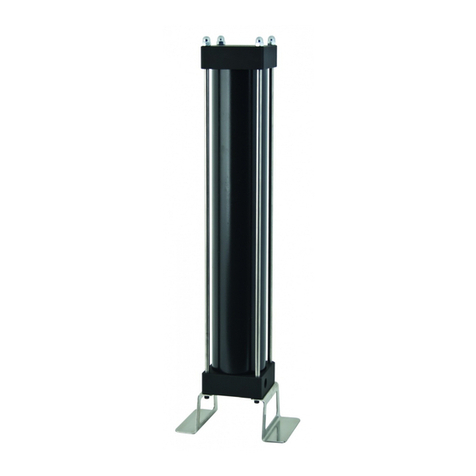
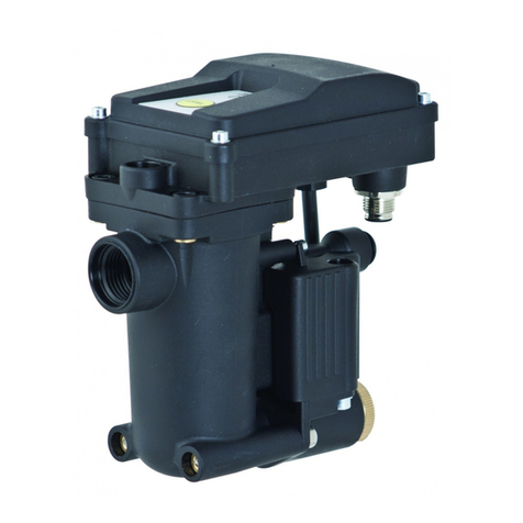
OMEGA AIR AOK20B User manual

Omega Air User Manual AOK20B v2.01 eng
Installation and operating
manual
AOK20B
Please read the following instructions carefully before installing automatic drain unit into
service. Trouble free and safe operating of the unit can only be guaranteed if
recommendations and conditions stated in this manual are respected.

AOK20B - Installation and operating manual
2
Components
Part
1
M6 screws
2
Drain housing
3
Manual drain
4
Orifice sealing
5
Floater
6
Housing sealing
7
Drain housing
8
M6 nuts
9
Connection nipple
1
3
5
6
7
8
2
4
9

AOK20B - Installation and operating manual
3
Technical data
CALCULATION OF CAPACITY
For rough calculation of discharge capacity at certain pressure use following equation:
𝑄=63�∆𝑝 Example: if operating at 7barg; 𝑄=63√7 = 166,7
MATERIALS
Housing material
Aluminium (EN-AC-46000)
Fittings, Screws
Brass, Brass-zinc plated, Steel
Floater
Stainless steel 1.4301
Sealing
NBR
Cover
PA 6
Operation pressure range
0 – 20 bar / 0 – 290 psi
Minimum reccomended operating pressure
1,5bar (g)
21,8 psi
Drain capacity (7 bar / 101 psi)
167 l/h
0,1 scfm
Drain capacity (16 bar / 235 psi)
252 l/h
0,15 scfm
Operating temperature range
1,5 – 65°C
35 - 149 °F
Operating media
Condensate (air, water, oil); Non-agressive
Inlet connection
G ½” (NPT on request)
Outlet connection
G ½” (NPT on request)
Reservoar volume
0,4 l
Mass
0,6 kg
Dimensions A x B x C [mm]
135 x 110 x 130
Valve type
Direct acting, Normally closed
Discharge orifice cross cection
1,8mm
0,0708 inch

AOK20B - Installation and operating manual
4
Safety instructions
Depressurize the system before carrying out any work on the piping.
Installation and maintenance work may only be carried out when the device is
not under pressure.
Installation and maintenance work may only be carried out by trained and
experienced staff.
Do not exceed max. operating pressure or operating temperature range (see
data label).
Do not use the device in hazardous areas with potentially explosive
atmospheres.
Use original spare parts only.
Use the device for the appropriate purpose only.
Appropriate use
AOK20B series condensate drain is intended exclusively for the following purpose:
Draining condensate from compressed air system (air compressors, air
receivers/pressure vessels, air dryers and air filters).
Any other form of use or one going beyond this shall be considered as inappropriate. We
shall have no liability whatsoever for any damage incurred as a result.

AOK20B - Installation and operating manual
5
Operating
Drain is installed bellow pressure vessel, filter element, dryer, cyclone separator or similar
pressure system element. Through G ½” connection on the top condensate accumulates in
the drain reservoir. Increasing water level rise the floating buoyancy. When the condensate
level is high enough the floater unblocks the discharge orifice and the condensate is purged
out through G ½” output connection. When condensate level drops floater drops with it and
blocks the discharge orifice. This operation prevents air loss.

AOK20B - Installation and operating manual
6
Installation
Before connecting the drain, blow compressed air through the piping in order to thoroughly
clean out any impurities within it.
Install the AOK20B at a level below the receiver, if not the receiver will fill up with
condensate.
Install the optional connection nipple (9) in order to allow air equalisation. The connection
receiver-nipple-AOK20B must be done without any extra pipe or filter.
After initial run, open AOK20B and clean all components.
It is strongly recommended that waste condensate from discharge port is connected to
water treatment application, such as WOSm series water oil separator to protect the
environment from pollution and to comply with environmental laws.
Once per year make a visual check of the drain and make sure there is no visual damage or
leakage. Clean interior of the reservoir regularly. Intervals of cleaning depend on
contamination of condensate. Replace the sealings if necessary.

AOK20B - Installation and operating manual
7
RECCOMENDATIONS
•We recommend the use of ball valve between pressure vessel and inlet connection.
•We recommend the use of strainer element between pressure vessel and inlet
connection.
•We recommend the use of nipple with venting tube to avoid generation of air
bubbles. Nipple is screwed in inlet connection and is optional equipement.
Maintenance
WEEKLY: Open (screw carefully) the discharge valve and let the condensate flow out
until the compressed air will blow through for few seconds. If a significant amount of water
(more than 0.5 litres) exits the valve then the drain must be thoroughly cleaned.
YEARLY: Dismantle the drain and clean all components. Do not use solvents to clean
rubber components.
Service:
It is recommended to clean reservoir at least once a year. Sealing elements are subject to
wear, which depends on various operating parameters such as pressure, temperature, dirt
content, etc. It is also recommended to change sealings.
Attention
Before beginning maintenance work depressurize the unit.
Spare parts:
Replacement sealings are available on demand. Please contact your distributor or
manufacturer.

AOK20B - Installation and operating manual
8
Warranty exclusion
The guarantee shall be void if:
The installation and operating manual was not followed with respect to installation,
initial commissioning and maintenance.
The unit was not operated properly and appropriately.
The unit was operated when it was clearly defective.
Non-original spare parts or replacement parts were used.
The unit was not operated within the permissible technical parameters.
Unauthorized constructional changes were made to the unit or if the unit has been
opened/disassembled by an unauthorized person.
OMEGA AIR d.o.o. Ljubljana
Cesta Dolomitskega odreda 10
SI-1000 Ljubljana, Slovenia
Tel.: +386 (0)1 200 68 00
Fax.: +386 (0)1 200 68 50
E-mail: info@omega-air.si
www.omega-air.si
Table of contents
Other OMEGA AIR Laboratory Equipment manuals