OMEGA AIR EMD Series User manual

Please read the following instructions carefully before installing the product. Trouble free and
safe operating of the product can only be guaranteed if recommendations and conditions
stated in this manual are respected.
3403276 –Omega_Air_User_Manual_Condensate_Drain_EMD_serija_eng_28012020
Installation and Operating
Manual
EMD series
(Automatic electronic condensate drains)

EMD Installation and operating manual
2 www.omega-air.si
Description
EMD series drains are electronically controlled condensed water drains that discharges
water trapped in the lowest parts of compressed air installation out of the system. This
water is a condensed water vapor that is always present in the atmosphere. Because of laws
of physics, some vapor always condenses during compression of air.
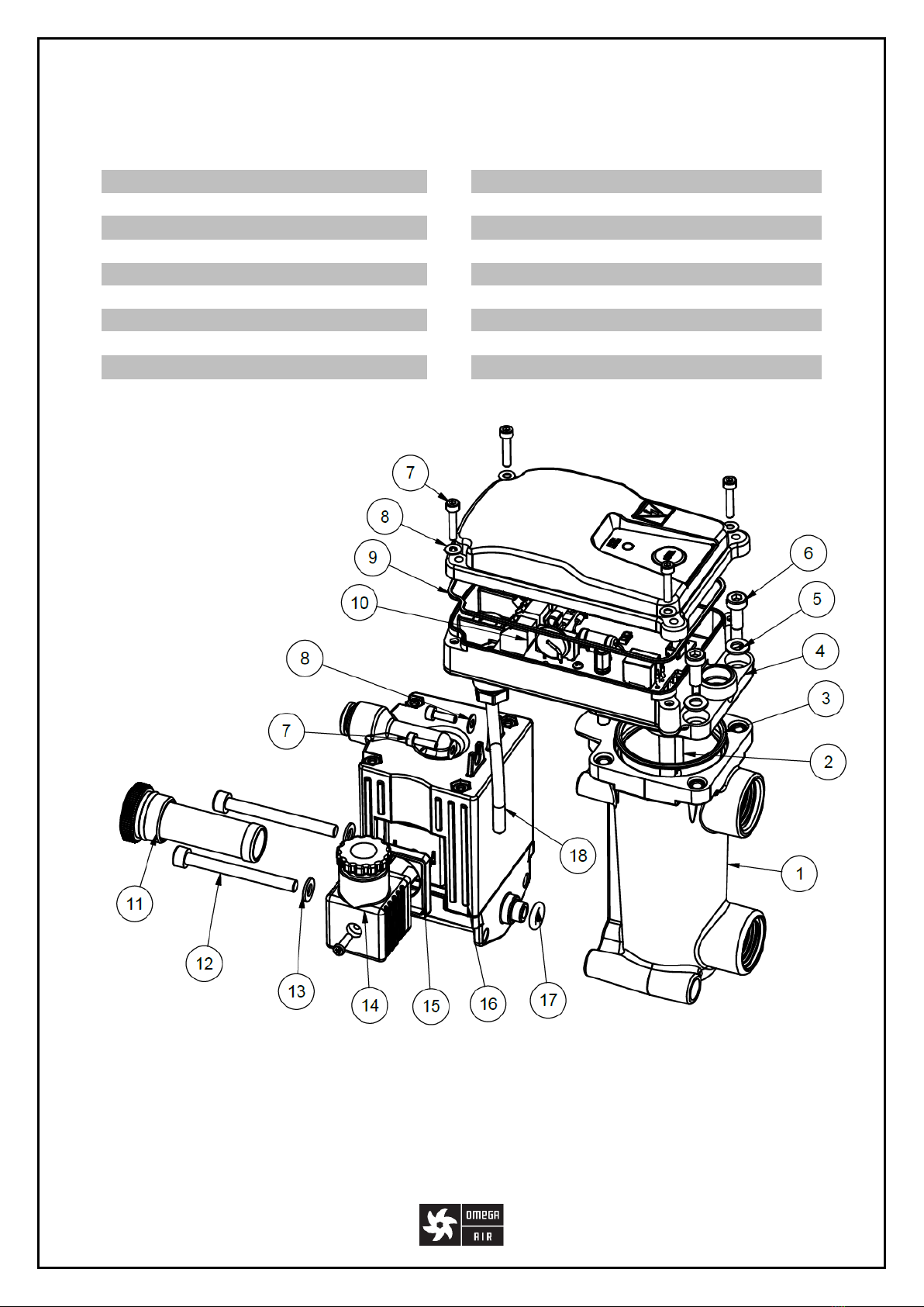
The EMD series drains consists of a water tank, valve assembly and electronics. The water
tank should be the lowest part of the compressed air system where condensed water
collects. In the tank, there is a water level sensor. This way, electronics could detect the tank
is full. Then, it operates the electromagnetic valve to discharge condensed water from
compressed air system. The valve is located in the valve assembly which is constructed so,
that it can be replaced easily. Another part of the valve assembly is a strainer where solid
parts of debris are intercepted. The strainer is located in front of EMD so that it could be
reached easily.
In the condensed water leaving the EMD, there are still small particles of rust and remains of
compressor oil. Oil must be removed before the water is drained to sewage system. To
remove oil, water-oil separator WOS or WOSm device could be used.
Because of its construction, the EMD could be attached to the compressed air system
horizontally or vertically. Under the pressure vessel or under the refrigerator dryer, the EMD
is fixed horizontally whereas under filters, it is more convenient to fix it vertically.
The valve is operated by electronics. It opens the valve when a button on the electronics
cover is pressed or when water level in the tank reaches threshold. Occasionally, a timed
venting mode that combines water level triggered discharging and timed venting is desired.
By pressing the test button, we could see if EMD is operational. Besides, the test button
makes possible to discharge water that has collected in a system during maintenance
manually.
The main mode of operation is a water level triggered discharging. The valve opens when
water level in EMD’s tank reaches threshold and it closes back before the tank is empty. This
way, only condensed water is discharged and no compressed air is lost.
In the timed venting mode, the valve is opened when water level reaches threshold, too.
Besides, when the valve is closed continuously for a predetermined period, it is opened
shortly although there is no water in the tank. During working day, water in EMD collects
rapidly so that venting period would never expire and there are no air losses. When
production rests, EMD is opening its valve. But since these discharges are short and sparse,
air losses are small. The timed venting mode should be used when there is a lot of debris in
condensed water and piping upward the EMD could not be inclined enough. Such situation is
quite common under pressure vessels. It may happen that air could not escape from the
tank upward the piping and while there is air around water level sensor, the EMD would
never open. In the timed venting mode, the valve is opened after the venting period has
expired and trapped air is allowed to escape through drainage. Now, condensed water can
reach water level sensor and EMD is opening its valve until all collected water is discharged.

EMD Installation and operating manual
www.omega-air.si 3
The timed venting mode is disabled initially since situations when this mode is needed are
rare. The mode could be enabled through the service network.
To service network, only types of EMD with communication electronics built in could be
connected. The service network is used for uploading data that are collected in EMD during
its operation. The data are elapsed hours, number of water discharging, current water level
in the tank and other data that could help to supervise and troubleshoot the system.
Through the service network, some operating parameters of EMD like venting period in
timed venting mode could be set. Additionally, valve could be operated remotely.
Features:
No loss drain
EMD could be fixed horizontally or vertically
Strainer is located front of EMD so that it could be reached easily
Optional time venting mode of operation
Optional Alarm/ Warning output and Service Network Protocol for remote
surveillance
Elapsed hour counter, valve operating counter and other data collection
Easy replacement of parts due to wear

EMD Installation and operating manual
4 www.omega-air.si
Components
Do not disassemble Valve assembly, water level sensor and electronics!
EMD 12
1
Water tank
9
Sealing, O-Ring 100 x 1.5
2
Water level sensor
10
Electronics
3
Sealing, O-Ring 42 x 2.5
11
Strainer Insert
4
Electronic housing
12
Bolt M5x50 DIN 912
5
Screw M5x12 DIN 912
13
Washer 5.3 DIN 125A
6
Screw M3x16 DIN 912
14
Valve Assembly
7
Washer 3.2 DIN 125A
15
Sealing, O-Ring fi 7x2,5
8
Electronic housing cover
16
Sealing, O-Ring 14 x 2.0

EMD Installation and operating manual
www.omega-air.si 5
EMD 25
1
Water tank
10
Electronics
2
Water level sensor
11
Strainer Insert
3
Sealing, O-Ring 42 x 2.5
12
Bolt M5x50 DIN 912
4
Electronic housing
13
Washer 5.3 DIN 125A
5
Washer 5.3 DIN 125A
14
Valve connector
6
Screw M5x12 DIN 912
15
Connector sealing
7
Screw M3x16 DIN 912
16
Valve assembly
8
Washer 3.2 DIN 125A
17
Sealing, O-Ring fi 7x2,5
9
Sealing, O-Ring 100 x 1.5
18
3 x 0,75 cable

EMD Installation and operating manual
6 www.omega-air.si
EMD 75
1
Water tank cover
11
Electronic housing cover
2
Water tank
12
Screw M3x16 DIN 912
3
Nut M5 DIN 934
13
Washer 3.2 DIN 125A
4
Sealing, O-Ring fi 7x2,5
14
Sealing, O-Ring 100 x 1.5
5
Screw M5x16 DIN 912
15
3 x 0,75 cable
6
Sealing O-Ring fi 95x2
16
Strainer Insert
7
Sealing, O-Ring 42 x 2.5
17
Connector screw
8
Electronics housing
18
Valve connector
9
Washer 5.3 DIN 125A
19
Connector sealing
10
Screw M5x12 DIN 912
20
Valve assembly

EMD Installation and operating manual
www.omega-air.si 7
EMD 150
1
Water tank cover
11
Electronic housing cover
2
Water tank
12
Screw M3x16 DIN 912
3
Nut M5 DIN 934
13
Washer 3.2 DIN 125A
4
Sealing, O-Ring fi 7x2,5
14
Sealing, O-Ring 100 x 1.5
5
Screw M5x16 DIN 912
15
3 x 0,75 cable
6
Sealing, O-Ring fi 95x2
16
Strainer Insert
7
Sealing, O-Ring 42 x 2.5
17
Connector screw
8
Electronics housing
18
Valve connector
9
Washer 5.3 DIN 125A
19
Connector sealing
10
Screw M5x12 DIN 912
20
Valve assembly

EMD Installation and operating manual
8 www.omega-air.si
EMD12 Technical data
Type
EMD 12 230V
EMD 12 115V
EMD 12 24Vac
EMD 12A 24Vdc
Voltage
230V ac,
50 –60Hz
115V ac,
50 –60Hz
24V ac,
50 –60Hz
24V dc
Fuse inside EMD
5x20 1A T
2A
2A
Power
10VA
10VA
8.5W
Operating
pressure range
1 –16 bar
(14 –232 psi)
0 - 8 bar
(0-116 psi)
Drain capacity
@7 bar (101 psi)
12 l/h,
(0.007 cfm)
Operating
temperature
range
1,5°C – 65°C
Protection class
54
Inlet connection
G 1/2" (parallel thread)
Outlet
connection
Push connection for tube ø8
Mass
0.55 kg
Dimensions A x B
x C x D [mm]
133 x 76 x 147 x 65

EMD Installation and operating manual
www.omega-air.si 9
EMD 25 Technical data
Type
EMD 25 230V
EMD 25 115V
Voltage
230V ac, 50 –60Hz
115V ac, 50 –60Hz
Fuse inside EMD
5x20 1A T
Power
22 VA
Operating pressure range
1 –16 bar
(14 –232 psi)
Drain capacity @7 bar (101
psi)
25 l/h
(0.014 cfm)
Operating temperature
range
1,5°C – 65°C
Protection class
54
Inlet connection
G 1/2" (parallel thread)
Outlet connection
Push connection for tube ø8
Mass
0.73 kg
Dimensions A x B x C x D x E
[mm]
140 x 85 x 166 x 65 x 72,5

EMD Installation and operating manual
10 www.omega-air.si
EMD 75 Technical data
Type
EMD 75 230V
EMD 75 115V
Voltage
230V ac, 50 –60Hz
115V ac, 50 –60Hz
Fuse inside EMD
5x20 1A T
Power
22 VA
Operating pressure range
1 –16 bar
(14 –232 psi)
Drain capacity @7 bar (101
psi)
75 l/h
(0.044 cfm)
Operating temperature
range
1,5°C – 65°C
Protection class
54
Inlet connection
G 1/2" (parallel thread)
Outlet connection
Push connection for tube ø8
Mass
1.2 kg
Dimensions A x B x C x D x E
[mm]
170x 99 x 162 x 74 x 60

EMD Installation and operating manual
www.omega-air.si 11
EMD 150 Technical data
Type
EMD 150 230V
EMD 150 115V
Voltage
230V ac, 50 –60Hz
115V ac, 50 –60Hz
Fuse inside EMD
5x20 1A T
Power
22 VA
Operating pressure range
1 –16 bar
(14 –232 psi)
Drain capacity @7 bar (101
psi)
150 l/h
(0.088 cfm)
Operating temperature
range
1,5°C – 65°C
Protection class
54
Inlet connection
G 1/2" (parallel thread)
Outlet connection
Push connection for tube ø8
Mass
1.3 kg
Dimensions A x B x C x D x E
[mm]
199 x 99 x 162 x 70 x 68

EMD Installation and operating manual
12 www.omega-air.si
Signal connection
Version
Service Network Connection
Alarm output
EMD 12
No
No
EMD 12A
No
Yes
EMD 12C
Yes
Yes
EMD 25
No
No
EMD 25A
No
Yes
EMD 25C
Yes
Yes
EMD 75
No
No
EMD 75A
No
Yes
EMD 75C
Yes
Yes
EMD 150
No
No
EMD 150A
No
Yes
EMD 150C
Yes
Yes
* EMD 12 24V ac only available in normal and alarm version
** EMD 12 24V dc only available in alarm version
For more details about signals see chapters ‘Electrical wiring’ and ‘Service Network and
‘Alarm’!

EMD Installation and operating manual
www.omega-air.si 13
Safety instructions
Installation and maintenance work may only be carried out when the device is not
under pressure. To depressurize the device, close ball valve and press the test button
on device until pressure in it drops.
Installation and maintenance work may only be carried out by trained and
experienced personnel.
Installation and maintenance workers must use proper safety / protection equipment
(e.g. protection gloves, protection goggles, …)
Disconnect electrical power supply before opening the top cover of the device.
Installation and maintenance work may only be carried out when electrical power
supply is disconnected.
Electrical work must always be carried out by qualified electrician.
Do not exceed maximal operating pressure or operating temperature range (see data
label).
Do not use the device in hazardous areas with potentially explosive atmospheres.
Use original spare parts only.
Use the device for the appropriate purpose only.
Appropriate use
EMD series electronic condensate drains are intended exclusively for the following purpose:
Draining condensate from compressed air system (air compressors, air
receivers/pressure vessels, air dryers and air filters).
Any other form of use or one going beyond this shall be considered as inappropriate. We
shall have no liability whatsoever for any damage incurred as a result.

EMD Installation and operating manual
14 www.omega-air.si
Installation guidelines
Keep to the safety rules when working with
pressure equipment.
The EMD should be connected to a pressure
system by ball valve and pipe union.
This way, it is not needed to depressurize the
whole system each time strainer cleaning or other
maintenance takes place.
Make sure that inlet connection has parallel
thread. Do not use tapered thread!
The EMD series could be mounted horizontally (left) or vertically (right). But, it must not be rolled aside
more than ±15°. The horizontal position is preferred in case of a lot of debris in condensed water.
Do not connect several condensed water sources to one drain device because air would bypass filtering
(left). Instead, each spot where condensed water collects must have its own condensate drain device
(right).
Drainage piping must be built without traps that would trap air in the EMD and prevent condensed
water to enter it (left). Additional venting would not help because debris collects in the lowest part of
drainge pipe and clogg it (right).
EMD
EMD
EMD
EMD
G 1/2"
Internal thread
G 1/2"
Internal thread
G 1/2"
Internal thread
G 1/2"
Internal thread

EMD Installation and operating manual
www.omega-air.si 15
Horizontal drainage pipes must be inclined so that air could escape from EMD and that debris is flushed
toward EMD (left). When horizontal drainge pipes are long, venting should be built (right).
If if the bottom connection is used, the height of
the upper connection must be lower than the
lowest point of the condensate level. Upper
unused connection must be properly sealed
(pluged).
Use upper connection to mount venting line back
to pressure equipment (e.g. pressure vessel).
Venting line prevents creation of air bubbles
assuring constant flow of condensate into the
drain.
Venting is made by T-piece.
The T-piece should be located just infront of valve
so that path from the EMD tank to the venting
piece is as short as possible to prevent
compressed air from being trapped in the tank.
Venting with T-piece can only be used with
upper inlet connection.
Venting is made through auxiliary inlet.
EMD has provisions for building an auxiliary inlet
where venting could be connected. This auxuliary
inlet is not implemented in the standard EMD.
Conntact manufacturer for more information
about EMD with the auxiliary inlet.

EMD Installation and operating manual
16 www.omega-air.si
Electrical wiring:
Fully disconnect power from EMD before opening the cover of electronic compartment.
Please ensure that the installation is carried out according to valid regulations.
Power Connection Cable
2 x 0,75mm2+ PE
Oil resistant insulation recomended
Wires should be equipped with appropriate
ferrules. Make sure, that all strands of a wire are
fitted inside the ferrule.
Make sure that all wires are fitted into
terminals firmly!
Provide means for full disconnection of electric
power from EMD.
Do not connect EMD after protection device of heavy inductive load like compressor motor (left).
Instead, heavy inductive load and EMD should be protected separately (right).
After installation or maintenance work, press the test button to drain all condensed water
which has meanwhile collected in the compressed air system.
8 mm
L
N
PE
L
N
PE
M
L
N
PE
M

EMD Installation and operating manual
www.omega-air.si 17
EMD series 230Vac, 115Vac
EMD A series 230Vac, 115Vac
EMD C series 230Vac, 115Vac
EMD12 24Vac
EMD12A 24Vac
EMD12A 24Vdc
Power Connection
1
230Vac (115Vac) Neutral
2
230Vac (115Vac) Line
3
PE Conductor
Valve Connection
4
PE Conductor
5
Power line
6
Power line
Service Network (EMDC)
7
Alarm/W. (white X2.4 BE)
8
Transmit (blue X2.3 MO)
9
GND (brown X2.2 RJ)
10
Receive (black X2.1 CR)
Connector pins' description:
Alarm output (EMDA)
7
Alarm/ Warning
9
GND
Umax (at high impedance): 39V
Imax (at low impedance): 200mA
Ureverse: -0,7V
Power Connection
1
24Vac (grounded line)
2
24Vac
3
PE Conductor
Valve Connection
4
PE Conductor
5
Power line
6
Power line
Alarm output (EMDA)
7
Alarm/ Warning
9
GND
Umax (at high impedance): 39V
Imax (at low impedance): 200mA
Ureverse: -0,7V
Only EMD12 is currently
available in 24Vac version.
Power Connection
1
24Vdc positive pole
2
24Vdc negative pole
3
PE Conductor
Valve Connection
4
PE Conductor
5
Power line
6
Power line
Alarm output (EMDA)
7
Alarm/ Warning
8
GND
Relay contact: NO
Umax: 250Vac, 30Vdc
Imax: 8A
Only EMD12 is currently
available in 24Vdc version.
Touching electronics should be avoided, when cables are being connected!
Place the cover back immediately after the cables are connected!
GND
Transmit
Alarm
Receive
9
7
I
U
9
7
I
U
8
7
I
U
1
1
1
1
2
2
2
2
3
3
3
3
4
4
4
4
5
5
5
5
6
6
6
6
7
7
7
7
8
8
8
8
9
9
9
9
10
10
10
10
1
1
1
1
2
2
2
2
3
3
3
3
4
4
4
4
5
5
5
5
6
6
6
6
1
1
1
1
2
2
2
2
3
3
3
3
4
4
4
4
5
5
5
5
6
6
6
6
7
7
7
7
8
8
8
8
9
9
9
9
10
10
10
10
7,8
7,8
7,8
7,8

EMD Installation and operating manual
18 www.omega-air.si
Operation
By pressing the test button, valve is opened.
Green LED indicator shows water level in
tank. Short green flashes show that water in
tank is under the threshold.
Long green flashes indicate that the tank is
almost full.
When the tank is full, the green is on
permanently.
Red LED indicator is on permanently during
alarm mode.
Description:
In normal mode, EMD measures condensed water level in its tank. When level reaches
threshold, the valve is opened and water is discharged. Period between successive
discharges is from 5s to 7s long. When there is so much water, that EMD is not able to
remove it in 90s, it enters overload mode. In this mode, EMD opens its valve longer and
more frequently and its capacity is doubled. When EMD is still not able to discharge all the
water in 5min, it enters alarm mode. In alarm mode, EMD opens its valve so that it would
discharge 50% of its nominal capacity. The capacity in alarm mode is limited to limit air
losses in case of drain malfunction. EMD returns from overload or alarm mode to normal
mode when the tank gets empty.
Extreme amount of condensed water is possible after maintenance work. In front of EMD,
there is valve that is closed during maintenance. Behind this valve, condensed water collects.
After a while, there is so much water that EMD is not able to drain it without entering alarm
mode. To avoid entering alarm mode, test button should be pressed after each maintenance
work to discharge all condensed water manually.
Test button
Test button
Test button
Test button
LED indicator
LED indicator
LED indicator
LED indicator

EMD Installation and operating manual
www.omega-air.si 19
Service Network and Alarm
EMD variants C, which are equipped with communication electronics and connector could be
connected to a Service Network. The Service Network is a communication protocol used in
EMD and other compressed air equipment that allow a remote supervision. Work data could
be regularly read out of the device with a network or they could be read by a data logger. At
the same time, the Service Network could also serve as display and keypad for setting EMD’s
parameters at commissioning.
The Service network consists of two devices. These are a slave device which is EMD and a
master device. The master device could be a Service Network Reader SN-10.200. It’s a
handheld device that allows user to send command messages manually. It also comprises a
display where answer to command are read. In the table in next page, command message
codes specific to EMD are described. There, we see which work data are collected, which
parameters could be set and which remote commands are available in EMD.
More detailed description of Service Network Protocol could be found in document
SN-02.000, Service Network Protocol.
An alarm output is included in the service network. Nevertheless, it may be used to signal
alarm condition without being connected to service network. The alarm/warning output is
an open collector output and it shares its GND with serial communication of Service
Network. The output is in high impedance state during alarm. When EMD operates normally,
the output is in low impedance state.

EMD Installation and operating manual
20 www.omega-air.si
Important Service Network command message codes and their meaning
Code
Description
0x80…0x9F
Device data
0x84
Device Name
Manufacturer, manufacturer’s address and other important data.
0xA0…0xBF
Device State
0xA4
Device condition –general
0xA8
Power on counter, Elapsed hours counter
0xAC
Valve operation counter, Timed venting counter
0xB0
Overload timer, Alarm timer
0xB4
Processor events: Brown out counter, Voltage error counter
0xB8
Processor events: Watch dog reset counter, Software reset counter
0xBC
Water level sensor adjustment data
0xC0
Current working parameters
0xE0…0xF0
Settings
0xE4
Timed Venting - valve opened period
Values: 0.6s, 0.8s, 1.2s, 1.7s, 2.4s, Timed venting off (default)
0xE8
Timed Venting - Period to first operating of valve:
Values: 60min, 40min (default), 20min, 10min, 5min
0xEC
Timed Venting - Period between subsequent operating of valve:
Values: 120min, 60min (default), 40min, 20min, 10min
0xF0
Overload duration:
Values: 2min, 5min (default), 10min
0xF4…0xFF
Control
0xFB
Remote triggering of condensed water purging from EMD
Alarm in 24Vdc version –EMD 12
Contrary to ac versions of EMD 12, a dc version of EMD 12 has a built-in relay, which
provides a voltage free contact. It is of NO type and it is closed, when EMD 12 operates
normally.
This manual suits for next models
12
Table of contents
Other OMEGA AIR Laboratory Equipment manuals
Popular Laboratory Equipment manuals by other brands

Agilent Technologies
Agilent Technologies 1290 infinity user manual

Sartorius
Sartorius WZG Series operating instructions

Hoefer
Hoefer UVC5000 user manual

Endress+Hauser
Endress+Hauser Liquistation CSF48 operating instructions

SciCan
SciCan Bravo Operator's manual

Arthrex
Arthrex ROTOFIX 32A operating instructions