Omega 23221 Instructions for use

Hydraulic Truck Jack
Model
23221, 23222
23227
23301
23501
23991
Printed in Taiwan
23221-M2 rev 06/08
Operating Instructions & Parts Manual
Read this manual and follow all the Safety Rules and Operating Instructions before using this product.
SFA Companies
http://www.omegalift.com
Capacity
22 Ton
22/35 Ton
30 Ton
50 Ton
100 Ton
This is the safety alert symbol. It is used to alert you to potential personal injury hazards.
Obey all safety messages that follow this symbol to avoid possible injury or death.
!
!ADVERTENCIA
• Leer, comprender, y seguir las instrucciónes antes
de utilizar el aparato.
• El manual de instrucciónes y la información de
seguridad deben estar comunicado en lengua del
operador antes del uso.
• No seguir estas indicaciónes puede causar daños
personales o materiales.
!WARNING
To avoid crushing and related injuries:
NEVER work on, under or around a
load supported only by a hydraulic
jack. ALWAYS use adequately rated
jack stands.
Models 23221 & 23222 Models 23227, 23301, 23501 & 23991
U.S. Patent No's.
5,341,723 • 5,946,912

2
PREPARATION
Assembly (see Replacement Parts pages 6~9 for reference to parts location & assembly sequence)
Assemble, align and insert the handle assembly & handle position bar into the handle sleeve, then tighten the bolt
on handle sleeve to prevent accidental removal of handle while in use.
Before Use
1.
Verify that the product and application are compatible, if in doubt call Omega Technical Service (888) 332-6419.
2. Before using this product, read the operator's manual completely and familiarize yourself thoroughly with the
product, its components and recognize the hazards associated with its use.
3. To familiarize yourself with basic operation, locate and turn the release valve (handle knob):
a. Clockwise until rm resistance is felt to further turning. This is the ‘CLOSED’ release valve position used to
raise the load.
b. Counter-clockwise, but no more than 1 full turn from the closed position. This is the ‘OPEN’ release valve
position used to lower the load. The more you turn the release valve counter-clockwise, the faster the load
descends.
4. With ram fully lowered, remove the oil ller screw. Check oil level. Proper oil level should be just below the rim of
the opening. Reinstall the oil ller screw.
5. Pour a teaspoon of good quality air tool lubricant into the air supply inlet of the lift control valve. Connect to air
supply, then squeeze the lift control valve for 3 seconds to evenly distribute lubricant.
Note: These models are equipped with the popular 1/4" NPT air coupler. When installing a different air coupler of
your choice, ensure that thread tape or compound is used when servicing connections. To ensure dependable,
trouble free operation an inline air dryer and oiler is recommended.
6. Ensure that jack rolls freely. Raise and lower the unloaded ram throughout the lifting range before putting into
service to ensure the jack operates smoothly. Replace worn or damaged parts and assemblies with Omega
authorized replacement parts only.
Bleeding / Venting Trapped Air
With the release valve in the OPEN position (3b.) and with ram fully lowered, locate and remove the oil ller screw.
This will help release any pressurized air which may be trapped within the reservoir. Reinstall the oil ller screw.
SAFETY and GENERAL INFORMATION
Save these instructions. For your safety, read, understand, and follow the information provided with and on this jack
before using. The owner and operator of this equipment shall have an understanding of this jack and safe operating
procedures before attempting to use. The owner and operator shall be aware that use and repair of this product
may require special skills and knowledge. Instructions and safety information shall be conveyed in the operator's
native language before use of this jack is authorized. If any doubt exists as to the safe and proper use of this jack,
remove from service immediately.
Inspect before each use. Do not use if broken, bent, cracked or damaged parts are noted. Any jack that appears
damaged in any way, or operates abnormally shall be removed from service immediately. If the jack has been or
suspected to have been subjected to a shock load (a load dropped suddenly, unexpectedly upon it), immediately
discontinue use until jack has been checked by a factory authorized service center (contact distributor or manufacturer
for list of authorized service centers). It is recommended that an annual inspection be done by qualied personnel.
Labels and Operator's Manuals are available from manufacturer.
!
PRODUCT DESCRIPTION
These Hydraulic Truck Jacks are designed to lift, but not support, rated capacity partial vehicle loads consisting
of one end of a vehicle. Immediately after lifting, loads must be supported by a pair of appropriately rated jack
stands.
NEVER use a hydraulic truck jack as a stand-alone device. After lifting, immediately support
the lifted vehicle with a pair of appropriately rated jack stands.

3
SPECIFICATIONS
Model Capacity Jack Size (L x W) Min.
Height
Max.
Height
Hyd.
Range
Extension
Screw
Volume of
Hyd. Oil
23221 22 Ton 22-7/8" x 13-3/4" 9-7/8" 22" 11-3/8"
3-7/8"
490 mL
23222 22 Ton 21-7/8" x 12-3/8" 8-1/4" 21-7/8" 13-5/8" 490 mL
23227 22/35 Ton 21-5/8" x 13-7/8" 8-1/4" 19-5/8" 11-3/8"
N/A
490 mL
23301 30 Ton 22-7/8" x 12-1/2" 11" 18" 7" 890 mL
23501 50 Ton 22-7/8" x 13-3/4" 12" 19" 7" 1650 mL
23991 100 Ton 26" x 15-3/4" 12" 18-1/8" 6-1/8" 2550 mL
Figure 1 - Typical Truck Jack Nomenclature (23222 shown)
Handle Knob
(release valve)
Saddle
Carrying Handle
Oil Filler Screw
Wheel
Handle Sleeve
Handle Position
Release
Air Supply Inlet,
1/4NPT
Lift Control Valve
Adapter, 5"
(for 23222 only)
Handle
Extension Screw
(for 23221 & 23222 only)
Adapter Holder
(for 23221 & 23222 only)
Adapter, 2-1/2"
(for 23221 & 23222 only)

4
!
Be sure all tools and personnel are clear before
lowering load. Slowly open the release valve! The
more you turn the handle knob counter-clockwise, the faster the load will come down. Maintain control
of the rate of speed at which the load lowers at all times!
1. Raise load high enough to clear the jack stands.
2.
Remove jack stands carefully (always used in pairs).
3. Slowly turn handle knob counter-clockwise, but no more than 1 full turn. If the load fails to lower:
a. Use another jack to raise the vehicle high enough to reinstall jack stands.
b. Remove the malfunctioning jack and then the jack stands.
c.
Use the functioning jack to lower the
vehicle.
4. After removing jack from under the vehicle, fully retract the jack to reduce ram exposure to rust and
contamination.
!
!
!WARNING
• Study, understand, and follow all printed
materials provided with/on this product before use.
• Do not exceed rated capacity.
• This is a lifting device only!
• Immediately after lifting, support the load with
a pair of appropriately rated jack stands.
• Use only on hard, level surface.
• Lift only on areas of the vehicle as specied by
the vehicle manufacturer.
• Never wire, clamp or otherwise disable the lift
control valve to function by other than operator's
hand.
• No alterations shall be made to this product.
• Failure to heed these markings may result in
personal injury and/or property damage.
To avoid crushing and related injuries:
•
Never work on, under or around a load supported
only by hydraulic jack.
•
Always use adequately rated jack stands.
• Chock each unlifted tire in both directions.
• Do not use this device to lift, level, lower, support nor
move a house, mobile home, travel trailer, camper or
any building structure.
• Be alert and sober when using this product. Do not
operate under the inuence of drugs or alcohol.
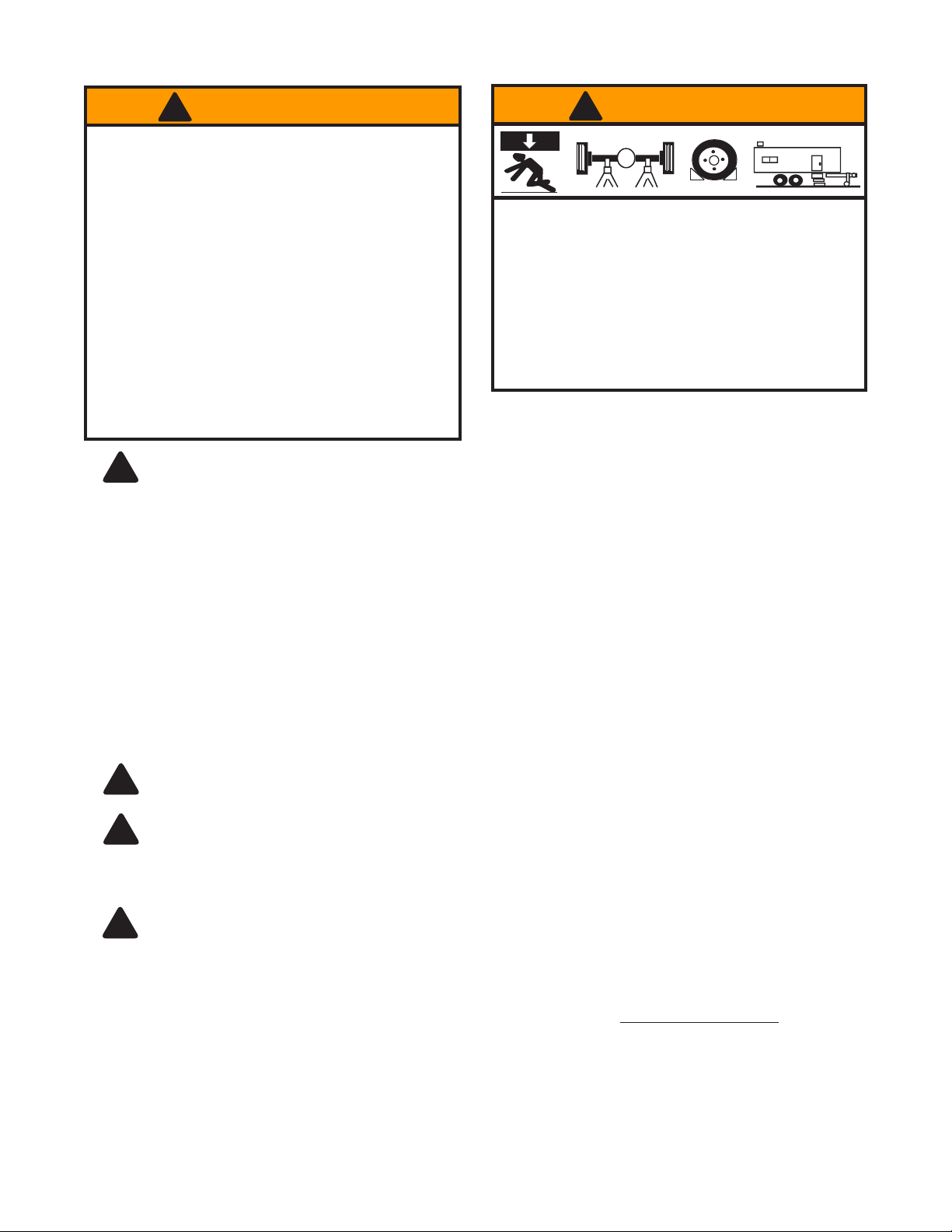
!WARNING
X
!The wheels provided with this jack are for positioning the jack under a load ONLY! The wheels are
not load wheels. Do not try to dolly or move the vehicle with the jack!
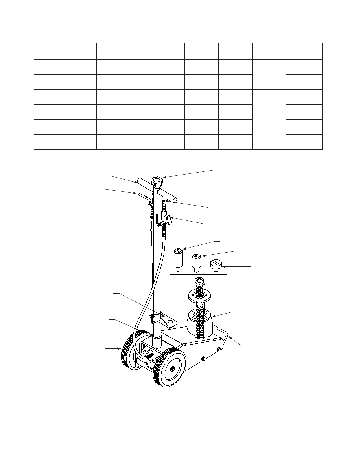
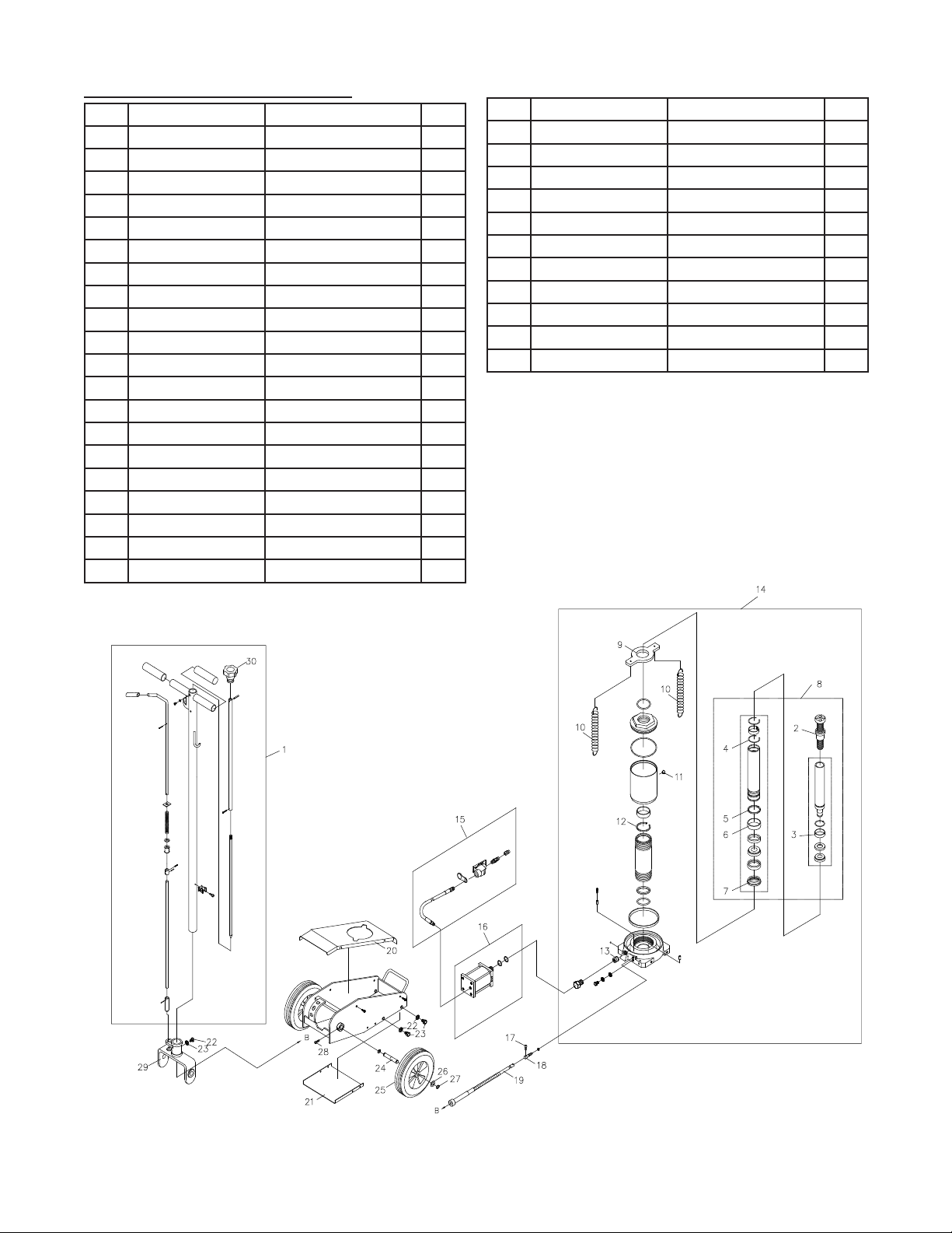
OPERATION (see Fig 1)
Lifting
Note: The jack is equipped with handle position lock. To adjust the handle, release lock device by pulling the lever
up, lever is spring loaded and will lock into desired position. Ensure lever locking mechanism is fully engaged before
leaving
1. Connect adequate air source to the air supply inlet.
2. Follow the vehicle manufacturer’s recommended guidelines for lifting. Engage the emergency brake and chock
each unlifted wheel in both directions to prevent inadvertent vehicle movement.
3.
Close the release valve by turning the handle knob clockwise until rm resistance is felt.
4. Center jack saddle under lift point, then squeeze the lift control valve until saddle contacts the lift point. To lift,
continue squeezing the lift control valve until load reaches desired height. Simply release your grip on the lift
control valve to end lift event.
5. Transfer the load immediately to appropriately rated jack stands.
Only attachments and/or adapters supplied by the manufacturer shall be used. Lift only on area of the
vehicle as specied by the vehicle manufacturer.
NEVER use hydraulic jack as a stand alone
device! ALWAYS transfer the lifted load IMMEDIATELY to
a pair of appropriately rated jack stands. Use one pair of jack stands per vehicle. Rated capacity is per
pair only! Do not exceed rated capacity.
Lowering

5
MAINTENANCE
Important: Use only good grade hydraulic jack oil. Avoid mixing different types of uid and NEVER use brake uid,
turbine oil, transmission uid, motor oil or glycerin. Improper uid can cause premature failure of the jack and the
potential for sudden and immediate loss of load. We recommend Mobil DTE 13M or equivalent.
Adding/ Changing Oil
For best performance and longest life, replace the complete uid supply at least once per year.
1. With saddle fully lowered remove cover plate, then oil ller plug.
2. Lay jack on its side and drain uid into a suitable container.
Note: Dispose of hydraulic uid in accordance with local regulations.
3. Set jack in its upright, level position.
4. Fill with oil. Proper oil level is just below the rim of the opening. Reinstall the oil ller screw.
Lubrication
A periodic coating of light lubricating oil to pivot points, axles and hinges will help to prevent rust and assure that
wheels move freely and the pump functions smoothly. To help ensure trouble free operation, an inline air dryer and
oiler is recommended.
Cleaning
Periodically check the ram for signs of rust or corrosion. Clean as needed and wipe with an oily cloth.
Note: Never use sandpaper or abrasive material on ram surfaces!
Storage
When not in use, store the jack with saddle fully lowered.
REPLACEMENT PARTS
(see pages 6 thru 9)
Not all components of the jack are replacement items, but are illustrated as a convenient reference of location and
position in the assembly sequence. When ordering parts, please give the Model number, part number and parts
description. Call or write for current pricing: SFA Companies 10939 N. Pomona Ave. Kansas City, MO 64153, U.S.A.
E-Mail: [email protected] Tel: (888) 332-6419 Fax: (816) 891-6599 Omega Website: http://www.omegalift.com
TROUBLESHOOTING
Symptom Possible Causes Corrective Action
Jack will not lift load • Release valve not tightly closed
• Load is too heavy
• Air supply inadequate
• Ensure release valve tightly closed
• Consider higher capacity jack
• Ensure adequate air supply
Jack will lift, but not maintain
pressure
•Release valve not tightly closed
• Hydraulic unit malfunction
•Ensure release valve tightly closed
• Discontinue use, contact Omega
technical service
Jack will not lower after unloading • Reservoir overlled
• Linkages binding
• Drain uid to proper level
• Clean and lubricate moving parts
Poor lift performance • Fluid level low
•Air trapped in system
• Ensure proper uid level
•With ram fully retracted, remove oil
ller screw to let pressurized air
escape. Reinstall oil ller screw
Will not lift to full extension • Fluid level low • Ensure proper uid level

6
Item Part No. Description Qty
1A09-4-2200-106 Handle Assembly 1
2506-9-0280-104 Handle Grip 2
3421-6-2202-209 Knob 1
4 601-4-0040-034 Spring Pin 1
5 653-1-0100-308 Bolt 1
6605-3-0100-203 Washer, Lock 5
7A07-6-1301-105 Handle Sleeve 1
8A09-6-3221-101 Cover Plate 1
9 609-1-0050-109 Screw 5
10 A07-4-3400-509 Wheel 2
11 611-3-0130-101 Washer 2
12 667-5-0127-005 C-clip 2
13 G53-3-2000-205 Air Motor 1
14 653-1-0100-106 Bolt 4
15 515-3-0140-103 Copper Gasket 1
16 A20060-0015 Air Hose Assembly 1
17 A20060-0006 Air Hose 1
18 A20060-0007 Lift Control Valve 1
19 A20060-0016 Air Coupler, Male,
1/4 NPT
1
20 A07-3-3300-307 Release Valve Cable 1
Figure 2 - Replacement Parts Illustration for Model 23221 & 23222
Replacement Parts for models 23221 & 23222:
Item Part No. Description Qty
21 A09-6-1701-105 Release Valve 1
22 554-7-0062-007 Oil Seal 1
23 649-1-0050-019 Screw 1
24 653-1-0080-025 Screw 2
25 661-2-0080-023 Nut 2
26 324-4-1900-208 Filler Screw Assy. 1
27 523-2-0196-016 Spring, 23221 4
523-2-0198-203 Spring, 23222 4
28 A07-3-1100-501 Extension Screw 1
29 A07-5-1108-105 Saddle 1
30 A07-5-1802-101 Spring Plate 1
31 A07-4-2900-100
Air Filter
1
32 A09-3-9901-206 Repair Kit
(includes
#15, 22, 26 & A~I)
-
33 A27010-0008 Piston, Air Motor #13 1
34 A09-1-1001-217
Hydraulic Unit, 23221
1
A09-1-1011-210
Hydraulic Unit, 23222
1
35 A07-6-3230-300 Wheel Axle 2
36 A09-6-3124-104 Base Plate, 23221 1
A07-6-3214-201 Base Plate, 23222 1
37 A09-6-1104-107 Adapter Holder 1
38 A07-6-1109-103 Adapter, 2 1/2" 1
39 A09-5-1103-109 Adapter, 5" (for
23222 only)
1
3
4
2
91
5
6
7
10 11 12
14
6
9
8
15
13,
(33)
16
17
18 19
20
24
25
26
27
28
29
30
A
B
C
D
E
F
23
22
21
G
H
GG
i
37
38
36
31
B
B
39
34
35

7
Item Part No. Description Qty
1A07-4-2100-108 Handle Assy. 1
2A22-3-1100-209 Extension Screw 1
3A22-6-1218-109 Collar 1
4 A22-6-1213-109 Retaining Ring 2
5 A22-6-1211-105 Retaining Ring 1
6A22-6-1219-101 Collor 1
7 A22-6-1217-208 Fixing Ring 1
8A22-3-1220-209 Piston Rod Assy. 1
9A22-6-1802-108 Cover 1
10 522-2-0260-030 Extension Spring 2
11 324-4-1900-208 Filler Screw 1
12 A22-6-1808-100 Retaining Ring 1
13 A20-4-1500-106 Hyd. Cartridge Assy. 1
14 A22-1-1001-113 Hyraulic Unit Assy. 1
15 A22-4-2040-107 Air Hose Assy. 1
16 A27-3-2000-104 Air Motor Assy. 1
17 649-1-0050-019 Hex. Socket Bolt 1
18 A20-6-1707-108 Release Valve 1
19 A07-3-3300-307 Flexible Joint Assy. 1
20 A22-6-3220-106 Cover Plate 1
Figure 3 - Replacement Parts Illustration for Model 23227
Replacement Parts for model 23227:
Item Part No. Description Qty
21 A22-6-1607-100 Base Plate 1
22 605-3-0100-203 Spring Washer 5
23 653-1-0100-014 Bolt 5
24 A232-6-3230-200 Wheel Axle 2
25 A22-4-3400-106 Rubber Wheel Assy. 2
26 511-3-0202-046 Washer 2
27 667-5-0180-009 Retaining Ring "C" 4
28 644-1-0060-053 Hex. Socket Bolt 2
29 A07-6-1301-105 Handle Fork 1
30 421-6-2202-209 Knob 1
** A22-3-9901-102 Repair Kit -

8
Figure 4 - Replacement Parts Illustration for Model 23301
Item Part No. Description Qty
1A07-4-2100-108 Handle Assembly 1
2506-9-0264-106 Handle Grip 2
3421-6-2202-209 Knob 1
4 601-4-0040-034 Spring Pin 1
5 653-1-0100-014 Bolt 5
6605-3-0100-203 Washer, Lock 5
7A07-6-1301-105 Handle Sleeve 1
8 A30-6-3220-100 Cover Plate 1
9 609-1-0050-109 Screw 5
10 A07-4-3400-509 Wheel 2
11 611-3-0130-101 Washer 2
12 667-5-0127-005 C-clip 2
13 A27010-0001 Air Motor 1
14 A270-01004-0420 Washer 1
15 A270-01014-0000 Gasket 1
16 A20060-0015 Air Hose Assembly 1
17 A20060-0006 Air Hose 1
18 A20060-0007 Lift Control Valve 1
Replacement Parts for model 23301:
Item Part No. Description Qty
19 A20060-0016 Air Coupler, Male,
1/4 NPT
1
20 A07-3-3300-307 Release Valve Cable 1
21 A20-6-1701-108 Release Valve 1
22 554-7-0062-007 Oil Seal 1
23 614-1-0050-047 Screw 1
24 A20-4-1500-106 Hyd. Cartridge 1
25 532-8-0050-024 Filter 1
26 324-4-1900-208 Filler Screw Assy. 1
27 522-2-0260-003 Spring 2
28 233-6-1104-107 Retaining Ring 1
29 236-6-1103-207 Saddle 1
30 A30-6-1802-102 Spring Plate 1
31 A07-4-2900-100
Air Filter
1
32 A30-3-9905-104 Repair Kit
(includes
#22, 26 & A~F)
-
33 A27010-0008 Piston, Air Motor #13 1
34 A30-1-1001-117 Hydraulic Unit 1
35 A07-6-3230-300 Wheel Axle 2
3
4
2
9
1
5
6
7
10
11
12
5
6
9
8
15
14
13,
(33)
16
17
18
19
20
22
21
23
24
25
26
27
28
29
30
A
B
C
D
E
F
31
34
35

Figure 5 - Replacement Parts Illustration for Model 23501
Item Part No. Description Qty
1A07-4-2100-108 Handle Assembly 1
2506-9-0264-106 Handle Grip 2
3421-6-2202-209 Knob 1
4 601-4-0040-034 Spring Pin 1
5 653-1-0100-014 Bolt 5
6605-3-0100-203 Washer, Lock 5
7A07-6-1301-105 Handle Sleeve 1
8 A30-6-3220-106 Cover Plate 1
9 609-1-0050-109 Screw 5
10 A22-4-3400-106 Wheel 2
11 511-3-0202-046 Washer 2
12 667-5-0180-009 C-clip 4
13 A27010-0001 Air Motor 1
14 A270-01004-0420 Washer 1
15 A270-01014-0000 Gasket 1
16 A20060-0015 Air Hose Assembly 1
17 A20060-0006 Air Hose 1
Replacement Parts for model 23501:
Item Part No. Description Qty
18 A20060-0007 Lift Control Valve 1
19 A20060-0016 Air Coupler, Male,
1/4 NPT
1
20 A07-3-3300-307 Release Valve Cable 1
21 A20-6-1701-108 Release Valve 1
22 554-7-0062-007 Oil Seal 1
23 614-1-0050-019 Screw 1
24 A20-4-1500-106 Hyd. Cartridge 1
25 532-8-0050-024 Filter 1
26 324-4-1900-208 Filler Screw Assy. 1
27 522-2-0260-003 Spring 2
28 A50-6-1802-108 Spring Plate 1
29 A50-1-1001-113
Hydraulic Unit
1
30 A07-4-2900-100
Air Filter
1
31 A22-6-3230-200
Wheel Axle
2
32 A27010-0008 Piston, Air Motor #13 1
33 A50-3-9905-100 Repair Kit
(includes
#22, 26 & A~E)
-
22
21
23
25
24
29
E
D
26 C
B27
28
A
B
B
20
12
11
10
5
8
3
4
9
7
9
6
2
6
1
5
18
17
16 19
30
14
13, (32)
15
12
31
9

10
Figure 6 - Replacement Parts Illustration for Model 23991
Item Part No. Description Qty
1A07-4-2100-108 Handle Assembly 1
2506-9-0264-106 Handle Grip 2
3421-6-2202-209 Knob 1
4 601-4-0040-034 Spring Pin 1
5 653-1-0100-014 Bolt 5
6605-3-0100-203 Washer, Lock 5
7A07-6-1301-105 Handle Sleeve 1
8A99-6-3220-101 Cover Plate 1
9 609-1-0050-109 Screw 5
10 A99-4-3400-202 Wheel 2
11 511-3-0202-046 Washer 4
12 667-5-0180-009 C-clip 2
13 A27010-0001 Air Motor 1
14 A270-01004-0420 Washer 1
15 A270-01014-0000 Gasket 1
16 A20060-0015 Air Hose Assembly 1
17 A20060-0006 Air Hose 1
18 A20060-0007 Lift Control Valve 1
Replacement Parts for model 23991:
Item Part No. Description Qty
19 A20060-0016 Air Coupler, Male,
1/4 NPT
1
20 A07-3-3300-307 Release Valve Cable 1
21 A20-6-1701-108 Release Valve 1
22 554-7-0062-007 Oil Seal 1
23 614-1-0050-019 Screw 1
24 A20-4-1500-106 Hyd. Cartridge 1
25 532-8-0050-024 Filter 1
26 324-4-1900-208 Filler Screw Assy. 1
27 522-2-0260-003 Spring 2
28 250-6-1103-201 Saddle 1
29 A99-6-1802-103 Spring Plate 1
30 A99-1-1001-118
Hydraulic Unit
1
31 A07-4-2900-100
Air Filter
1
32 A27010-0008 Piston, Air Motor #13 1
33 A99-3-9905-105 Repair Kit
(includes
#22, 26 & A~F)
-
34 A99-6-1302-103
Axle, Handle Sleeve
2
22
21
23
25
24
30
F
E
26 D
C27
29
B
B
B
20
12
11
10
5
8
3
4
9
7
9
6
2
6
1
5
18
17
16 19
31
14
13, (32)
15
11
34
28
A

ONE YEAR LIMITED WARRANTY
For a period of one (1) year from date of purchase, SFA Companies will repair or replace, at its option,
without charge, any of its products which fails due to a defect in material or workmanship under normal usage. This
limited warranty is a consumer's exclusive remedy.
Performance of any obligation under this warranty may be obtained by returning the warranted product, freight
prepaid, to SFA Companies Warranty Service Department, 10939 N. Pomona Ave., Kansas City, MO 64153.
Except where such limitations and exclusions are specically prohibited by applicable law, (1) THE
CONSUMER'S SOLE AND EXCLUSIVE REMEDY SHALL BE THE REPAIR OR REPLACEMENT OF DEFECTIVE
PRODUCTS AS DESCRIBED ABOVE. (2) SFA Companies SHALL NOT BE LIABLE FOR ANY CONSEQUENTIAL
OR INCIDENTAL DAMAGE OR LOSS WHATSOEVER. (3) ANY IMPLIED WARRANTIES, INCLUDING WITHOUT
LIMITATION THE IMPLIED WARRANTIES OF MERCHANTABILITY AND FITNESS FOR A PARTICULAR
PURPOSE, SHALL BE LIMITED TO ONE YEAR, OTHERWISE THE REPAIR, REPLACEMENT OR REFUND AS
PROVIDED UNDER THIS EXPRESS LIMITED WARRANTY IS THE EXCLUSIVE REMEDY OF THE CONSUMER,
AND IS PROVIDED IN LIEU OF ALL OTHER WARRANTIES, EXPRESS OR IMPLIED. (4) ANY MODIFICATION,
ALTERATION, ABUSE, UNAUTHORIZED SERVICE OR ORNAMENTAL DESIGN VOIDS THIS WARRANTY AND
IS NOT COVERED BY THIS WARRANTY.
Some states do not allow limitations on how long an implied warranty lasts, so the above limitation may not
apply to you. Some states do not allow the exclusion or limitation of incidental or consequential damages, so the
above limitation or exclusion may not apply to you. This warranty gives you specic legal rights, and you may also
have other rights, which vary from state to state.
SFA Companies
10939 N. Pomona Ave. Kansas City, MO 64153
888-332-6419
11

12
Contact:
SFA Companies
10939 N. Pomona Ave. Kansas City, MO 64153, U.S.A.
Tel:(888)332-6419 Fax:(816)891-6599
E-Mail:[email protected]
Omega Website: http://www.omegalift.com
Note Page
This manual suits for next models
5
Table of contents
Other Omega Automobile Accessories manuals
Popular Automobile Accessories manuals by other brands

Whispbar
Whispbar K604 Fitting Instructions for Basic Carrier

Firstech
Firstech 2WT13R-SF user manual

Radar Electronics
Radar Electronics PreView Buzzer FPV410B operating manual

TOP VEHICLE TECH
TOP VEHICLE TECH KWPOR8 installation manual

Brodit
Brodit 711027 quick start guide

FuelTech
FuelTech 5218 quick start guide

Westfalia
Westfalia 321 452 300 107 installation instructions

travall
travall TDG 1297 FITTING INSTRUCTION

STO N SHO
STO N SHO SNS 201 Installation procedures

Ericsson
Ericsson ALLEGRA EDACS Operator's manual

Prorack
Prorack K1226 instructions

FALCON RIDGE
FALCON RIDGE HO-BIGRED-MC01 Instructions for Installation and Care