Omega VSHYe Series User manual

OMEGA VSHYe SERIES
Installation and Operation Manual (IOM)
VERTICAL STACKED
HYBRID HEATING & COOLING
W/ INTEGRATED ERV
HIGH EFFICIENCY (HE)
MODEL: VSHYe
DEV. F
DOCUMENT RELEASE: OMEGA-VSHYe.F-IOM-2108
3325A Orlando Dr.
Mississauga, ON, L4V 1C5
T. 905.670.2269
omega-heatpump.com
omega@omega-heatpump.com
Inial Release

OMEGA-VSHYe.F-IOM-2108
i
TABLE OF CONTENTS
1. General Information, Warnings and Disclaimer ......................................................................1
2. Cabinet Dimensions ...............................................................................................................2
3. General Unit Information ........................................................................................................5
4. Inspection & Storage ..............................................................................................................5
Inspection of Unit .........................................................................................................5
Storage.........................................................................................................................6
5. Cabinet & Riser Installation ....................................................................................................6
For Shipped Loose Riser Shut-Off Valves....................................................................6
Cabinet Install ..............................................................................................................6
Riser Loop....................................................................................................................7
Servicing ........................................................................................................7
Flushing & Cleaning.......................................................................................7
Riser System Loop Temperature .................................................................................7
Cooling Season..............................................................................................7
Heating Season .............................................................................................7
Operating Limits.............................................................................................7
6. Chassis Installation.................................................................................................................8
Installation of Fittings and Hoses .................................................................................8
Chassis Install ..............................................................................................................8
7. Unit Start-Up...........................................................................................................................9
Checklist.......................................................................................................................9
Initial Start-Up ..............................................................................................................9
8. Controls ................................................................................................................................10
8.1 Microprocessor Controller ....................................................................................10
DIP Switch Settings .....................................................................................10
Thermostat Cable ........................................................................................10
Whisper Mode..............................................................................................10
Single Fan Speed Thermostat .....................................................................10
Multi Fan Speed Thermostat........................................................................11
Fan Control with ECM..................................................................................11
8.2 Sequence of Operation ........................................................................................11
8.3 Troubleshooting....................................................................................................11
8.4 ERV Controls & Operation ...................................................................................12
ERV Fan Settings ........................................................................................13
9. Web Browser Access ...........................................................................................................14
Test Mode ..................................................................................................................14
Web Based Access ....................................................................................................14
10. Maintenance Guide ............................................................................................................16

OMEGA-VSHYe.F-IOM-2108
1
IMPORTANT
READ THE FOLLOWING MANUAL PRIOR TO INSTALLATION, OPERATION and SER-
VICING THIS UNIT.
1. GENERAL INFORMATION & WARNINGS
SAFETY SYMBOLS – Warnings, Cautions & Notices
There are three advisory symbols used in this document to alert the reader:
Warning: Indicates a potentially dangerous situation which could result in death or
serious injury.
Caution: Indicates a possible hazardous situation which could result in possible
injuries or damage to unit and/or environmental pollution, or to alert against practic-
es that are unsafe.
Note: Identifies important information to the technician to complete the installation
correctly.
Responsible Refrigerant Practices
All technicians who handle refrigerants must be certified in accordance with local codes for
reclaiming, recovering, recycling and handling of refrigerants. Technicians must follow all
applicable local and federal laws.
Correct field wiring and grounding is required, failure to adhere and follow code
could result in death of serious injury. ALL FIELD WIRING MUST BE PER-
FORMED ONLY BY A QUALIFIED ELECTRICIAN. All wiring must be in accord-
ance of with the manufacturer’s specifications.
Wiring that is improperly installed and/or grounded could result in FIRE, ELECTRO-
CUTION, and other serious hazards. Manufacturer is not responsible for damage/
equipment or site issues resulting from the improper connections of the unit or the
use of improper controls.
Personal Protective Equipment (PPE) is mandatory. Technicians installing or ser-
vicing this unit must use all PPE including but not limited to: hard hats, safety glass-
es, cut resistant sleeves and gloves, electrical PPE, and fall protection.
Disclaimer
All units are certified and built in accordance to applicable government and industry stand-
ards. Any customer modifications performed without the express written approval from the
manufacturer are strictly prohibited and will void all warranties expressed or implied.
Modifications to the unit may result in hazardous or unexpected operation of the
unit. Modifications to the unit may result in a potentially hazardous situation result-
ing in equipment damage, property damage, injury or death.

OMEGA-VSHYe.F-IOM-2108
2
2. CABINET DIMENSIONS
VSHYe Cabinet Dimensions
W D Front Back Right/Left Top
VSHYe 030 3/4 14 x 8 8 x 14 10 x 12 12 x 12
VSHYe 040 1 14 x 8 8 x 14 10 x 14 12 x 12
VSHYe 050 1 1/4 14 x 8 8 x 14 10 x 16 14 x 12
VSHYe 060 1 1/2 14 x 8 8 x 14 10 x 16 14 x 12
VSHYe 080 2 18 x 8 8 x 18 14 x 18 14 x 14
VSHYe 100 2 1/2 18 x 8 8 x 18 14 x 20 16 x 14
VSHYe 120 3 18 x 8 8 x 18 14 x 20 16 x 14
Dimensions (in)
Capacity
(Tons)
Y
18
21.5
VSHPe Supply Discharge Opening ("W" X "H") inches
Z
22
25.5
Model
Cabinet
Size

OMEGA-VSHYe.F-IOM-2108
3
Left Hand (Type A1) and Right Hand (Type A4) are standard ERV port configurations..
VSHYe - ERV CONFIGURATIONS (TOP VIEW)
Notes:
Temporary riser supports provided (Contractor to remove and install permanent riser clamps fastening risers to the building
structure).
Return air opening is on the front of the unit.
Unit includes hose kits and manual shut off valves.
Optional risers are furnished with type L, M copper. Available 3 inch deep swage connections on same size piping.
Contractor to provide couplings where the piping is not swaged or for joining dissimilar piping sizes.
Use flexible duct connections to supply ducts and registers.
EA OA BE BE
OA
EA
OA
OA BE
BE EA
EA
EA
EA EA
EA
OA
OA OA OA
BE BE BEBE
A1 A2 A3 A4
B1 B3 B4
B2
Note 1, 2 Note 1, 2 Note 1, 2
Note 1, 2
EA - Exhaust Air to Outside
BE - Bathroom Exhaust to ERV
OA - Outside Air to ERV
Note:
1 - Left supply air discharge option not available
2 - Right supply air discharge option not available
Acceptable Riser Locations:

OMEGA-VSHYe.F-IOM-2108
4
VSHPe Assembly View
1. Supply, return and condensate riser eld “knockouts”.
2. Field “knockout” supply air openings (Front/Back/Side/Top) with 1-1/2” duct ange.
3. ERV Ports—Bathroom Exhaust, Exhaust Air, Outside Air.
4. Removable ERV core.
5. Chassis (HP shown)
6. Chassis service cover panel.
7. 1” air lter.
8. Acousc return air (R/A) panel for chassis, blower and electrical compartments.
9. ERV service panel.
10. Removable oponal supply discharge grille panel.
1
23
4
5
6
7
8
9
10

OMEGA-VSHYe.F-IOM-2108
5
3. GENERAL UNIT INFORMATION
BLOWER & MOTOR
The unit comes with a blower and motor assembly that
is mounted to a blower deck inside the unit cabinet, lo-
cated above the chassis behind the electrical box. Re-
moval of the blower/motor assembly is done through the
chassis compartment opening.
UNIT NAMEPLATES
The nameplate contains information about the unit in-
cluding model and serial numbers, electrical data and
refrigerant charge information. Each cabinet and chassis
come with a nameplate. Collecting the information on
the nameplate will be useful when contacting your local
customer service representative or when ordering parts.
CONTROLS
The unit comes with a factory supplied transformer. High
voltage connection is made on the left side of the cabi-
net and low voltage connections enter through the right
side of the cabinet, see cabinet dimensions.
ENERGY RECOVERY VENTILATOR (ERV)
Unit comes with integrated ERV. ERV Core is easily
removable for servicing through the Return Air panel. All
components and controls are factory installed and pre-
wired. ERV bathroom timer is field installed and wired
into ERV control board located in electrical box.
MICROPROCESSOR CONTROLLER
Unit comes with an advanced microprocessor controller
that monitors the safety switches and controls unit oper-
ation. The microprocessor board comes with a terminal
strip for wiring thermostat cable pigtails.
REFRIGERANT CONNECTIONS
Low and high pressure side refrigeration service ports
are located inside the compressor enclosure. Slide out
chassis and remove the top chassis sheet metal enclo-
sure to access fittings.
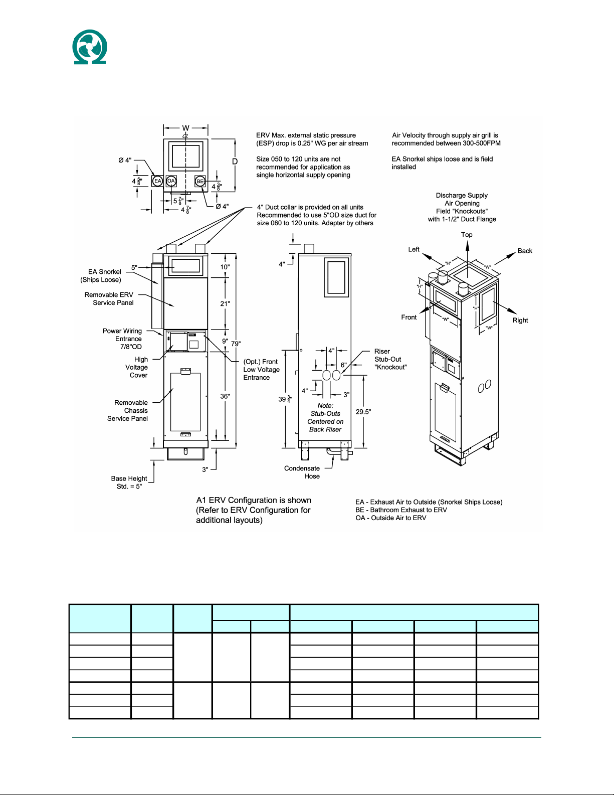
CABINET
The cabinet is a fully factory assembled one piece cabi-
net. Use flexible duct connections for connecting to sup-
ply ducts to prevent vibration and noise transmission into
occupant space.
RETURN AIR PANEL—ACOUSTIC
The Acoustic Return Air Panel is insulated with 1/2”
thick, acoustic insulation and removable without tools to
allow access to the filter and (optional) service discon-
nect switch. The panel is removed by swinging out and
lifting it off the support pegs.
The middle panel is a removable swing panel for ac-
cessing and servicing the ERV core, sensors and fans.
The upper panel comes as either a blank panel or with a
supply grille. Removal of this panel allows access to
outdoor air (OA) actuator.
THERMOSTAT
Unit comes standard with a factory provided 24 inch
long, 6-wire thermostat cable whip pre-wired to the con-
trol board terminal blocks.
4. INSPECTION & STORAGE
INSPECTION OF UNIT
Prior to the installation of the unit perform the following
checks:
• Visually inspect the packaging, cabinet and chassis
for signs of shipping damage prior to signing the bill
of lading. Check that the units match the sales order
by referring to the cabinet and chassis nameplate
information.
• Inspect the riser ends for any sign of damage.
• Verify breaker and power supply meet electrical
nameplate requirements of the unit.
• Check that the nameplate of the units matches the
floor plan layout.
When construction is not complete including concrete
core drilling, drywalling, plastering, painting or any work
that would contaminate the storage space all necessary
precautions are to be taken to prevent the cabinet and
chassis from becoming contaminated. Particulate infil-
tration (i.e. drywall dust) into cabinet and chassis coil
could result in equipment damage. Outgassing of con-
struction materials and supplies could result in prema-
ture corrosion (formicary corrosion) of the chassis air-
coil resulting in refrigeration system leaks. Chassis
should only be brought to job site and installed once
construction work is complete.
STORAGE
Both cabinet and chassis units are designed for indoor
use only. Care must be taken to protect the unit from
environmental damage. Store the chassis in an environ-
ment with a temperature above (32oF). To prevent con-
tamination the units should be stored indoors. For out-
door storage ensure:
• Units should be placed in an area that will not be
exposed to moisture damage. Units should be
placed on a dry surface and on a raised surface. Do
not stack units.
• Cover the units and any accessories with a water-
proof tarp.
• Failure to keep the units dry could result in the inte-

OMEGA-VSHYe.F-IOM-2108
6
rior insulation becoming wet and cause the growth
of mold which is known to cause odors and serious
indoor air quality problems and health issues.
• Chassis units must be stored in the upright position
to keep oil in the compressor.
• Riser ends should be capped if being stored on site
to prevent contamination from foreign objects and
debris.
Wet insulation can cause the growth of mold.
Any sign of mold growth in the interior insula-
tion should be removed, cabinet interior disin-
fected with anti-microbial cleaner and re-
placed prior to operating the unit.
Do not store cabinets on their side when
chassis units are inside. Chassis units should
always be stored and transported in the up-
right position otherwise damage to chassis
may occur.
The refrigeration system of these units con-
tains POE oil. PVC/CPVC piping is prone to
failure when in contact with POE oil. PVC/
CPVC piping should not be used for water
supply and return with any heat pump prod-
ucts as this may result in failure of the system
and serious property damage.
Do not rest or lean the unit on the risers. Do not use
the risers or stub-outs to pick up the unit. Only des-
ignated lift points should be used when moving or
lifting cabinets. Do not drop the risers.
5. CABINET & RISER INSTALLATION
Risers are designed to have slight adjust-
ments for riser system expansion and aligning
the stub-outs in the cabinet opening. When
installing risers, do not let riser stubs bottom
out in the riser swage.
Risers are designed to allow for 1-1/2 inches
of movement due to expansion and contrac-
tion. If the total calculated riser expansion ex-
ceeds ±1-1/2 inches the field must provide
expansion compensators.
Riser stub-outs should be located as centrally
as possible in the cabinet opening. Do not
allow stub-outs to rest or contact the sheet
metal opening.
Do not allow the risers to bottom out when
installing into the swage.
FOR SHIPPED LOOSE RISER SHUT-OFF VALVES
Visually inspect riser stub-outs and shut-off
valves for debris or damage.
Follow industry standard soldering practices
when soldering shut-off valves to riser stub-
outs.
Ensure riser stub-out surface is cleaned of any
residue, soot or oils. Failure to adequately
clean soldering surfaces can result in water
leaks, property damage and physical injury.
When soldering shut-off valves to riser stub
outs, adequately protect cabinet, insulation
and any other equipment from exposure to
flames and heat.
CABINET INSTALL
1. When cabinets are shipped with risers attached,
place cabinets in a horizontal position on the floor (do
not rest cabinet on the risers).
2. If required, install any field or factory supplied riser
extensions to the unit mounted risers.
3. Raise the entire cabinet slowly upright while at the
same time lowering the risers through the floor cut-out
opening. Align the risers to the matching swaged
(optional) section of the riser on the floor below.
4. Optional swaged sections are approximately 3 inch-
es deep. Risers should be inserted at a depth of ap-
proximately 2 inches into the 3 inch deep swage. Con-
firm risers penetrate at a minimum of 1 inch into the
swage. Do not allow the riser tailpiece to bottom out
fully into the 3 inch deep swage. This will allow for mi-
nor floor to floor variations, otherwise riser overlap may
not be sufficient on upper floors.
5. Align and center riser positions in the pipe chase
and level cabinet as necessary.
6. Secure the cabinet to the floor. Cabinet base comes
with factory mounted pads.
7. Center the riser stub-outs in the cabinet openings to
allow for riser expansion and prevent contact with cabi-
net sheet metal. Prevent riser stub-outs from contacting
sheet metal pass through otherwise damage to stub-
outs may occur, resulting in property damage.

OMEGA-VSHYe.F-IOM-2108
7
8. Secure risers to building structure as per engineer-
ing design specifications. Do not allow the risers to be
supported by the cabinets. Field supplied riser compen-
sators are required if the temperature range of the sys-
tem exceeds the expansion and contraction limit.
9. Using industry accepted soldering and brazing
standards and materials to solder or braze the riser
joints.
10. Connect supply ducts and discharge grilles.
11. Connect all ERV ducts to their corresponding con-
nections.
RISER LOOP
Servicing
To enable system flushing, servicing and balancing of
supply and return risers the following field supplied com-
ponents are required: shut-off valves, drain tees and
drain valves, and flow measuring devices. Refer to the
job site engineering design specifications and building
drawings for more detailed information.
Flushing & Cleaning
Once the riser system is complete the riser system must
be flushed, cleaned and re-filled and chemically treated.
Do not connect chassis to the water circulating system
when flushing is being conducted to prevent debris and
fouling of the water side components of the chassis (i.e.
auto balancing valve, auto shut-off valve, coaxial coil).
Do not flush and clean riser system with
chassis units connected. Do not allow the
flushing and cleansing solutions to flow in
the chassis water coil. Damage to water
components may occur.
Supply and return pipes must be interconnected, at a
minimum in the top and bottom units of each riser, with
factory supplied hoses to properly flush system and en-
sure adequate elimination of foreign material and clean-
ing of riser system.
1. Use only clean water to fill water circulation system.
Fill the water circulating system at the municipal water
makeup connection with all air vents opened.
2. After air vents have been sequentially closed and riser
system is primed begin water circulation of the system to
purge remaining trapped air bubbles.
3. Shut off the circulating pump and open all the drains
and vents to completely drain the system.
4. The riser system should be cleaned after the initial
flush and flushed a second time to adequately rinse the
riser system of cleaning solution.
Chassis installation is permitted once the riser system is
thoroughly flushed, cleaned, and water loop is chemical-
ly treated and commissioned by the riser treatment com-
pany and contractor.
RISER SYSTEM LOOP TEMPERATURE
Correct riser system loop temperature settings are im-
portant for optimal unit operation. Temperatures outside
of the recommended range will affect overall unit operat-
ing performance (capacity and efficiency), long term
reliability and sound performance.
Cooling Season
In cooling mode recommended riser loop temperatures
should be maintained between 90oF to 115oF. Higher
riser loop temperatures reduce unit cooling capacity and
efficiency, and increase sound levels. Lower riser loop
temperatures will increase unit operating efficiency.
Operation of riser loop temperatures above 120oF EWT
is not permitted. Refer to Table 2: Unit Operation Limits.
Heating Season
In heating mode riser loop temperatures should be
maintained between 90oF to 115oF for standard range
operation. Do not set loop temperatures above 120oF.
Operating Limits
Design limits can not be combined. Combining maxi-
mum or minimum limits is not allowed. This could ex-
ceed the operation and design limits of the unit.
For example: It is not allowed to combine maximum en-
tering air temperature (EAT) limits with maximum enter-
ing fluid temperature (EFT) limits.
Table 2: Unit Operation Limits
Heating
DB WB DB
Std. Entering Air Temperature (EAT) 75oF63oF68oF
Min. Entering Air Temperature (EAT) 65oF55oF50oF
Max. Entering Air Temperature (EAT) 85oF71oF85oF
Cooling Heating
Std. Entering Water Temperature (EWT) 85oF105oF
Min. Entering Water Temperature (EWT) 50oF90oF
Max. Entering Water Temperature (EWT) 120oF120oF
Cooling
Air Limits
Standard Range
Fluid Limits
Min. CFM/Ton 300 Min. GPM/Ton 2
Design CFM/Ton 400 Design GPM/Ton 3
Max. CFM/Ton 450 Max. GPM/Ton 4
Fluid GPM Limits
CFM Limits

OMEGA-VSHYe.F-IOM-2108
8
6. CHASSIS INSTALLATION
Do not apply plumbers putty, pipe dope or
sealing tape to NPSM fittings.
Always use a back-up wrench when tightening
hoses or fittings. Damage to copper pipes and
solder joints could result in serious equipment
and property damage.
Check hoses and fittings for any visible dam-
age or debris.
INSTALLATION OF FITTINGS AND HOSES
Upon removal of service cover panel check cabinet inte-
rior for construction debris and dust. Clean out all dust
and debris.
Close riser shut-off valves and disconnect factory hoses
from riser supply or return shut off valves.
Units with NPSM Riser and Chassis Fittings
Connect the supplied hoses to the Male-NPSM riser
shut-off valves. Do not apply pipe dope or pipe sealant
to NPSM fittings. Always use a back-up wrench. Fin-
ger tighten hose and tighten with back-up wrench
approximately 1/6 turn. DO NOT OVERTIGHTEN.
See Hose Kit Details.
Units with NPT Riser and Chassis Fittings
Connect the supplied male-male (NPT/ NPSM) cou-
plings to the Female-NPT supply and return riser shut-
off valves. Do not apply pipe dope to the NPSM fit-
tings, as these are JIC style fittings.
Connect the supplied hoses to the riser shut-off valves.
Always use a back-up wrench. DO NOT OVERTIGHT-
EN.
CHASSIS INSTALL
1. Remove chassis packaging, leaving cardboard ship-
ping cover on the air coil cover in place. Check chassis
nameplate to verify chassis model matches cabinet
model for compatibility.
2. Align chassis with front of the cabinet and tilt chassis
so that the back aligns with the cabinet rails.
3. Slide chassis into cabinet partially. Check to ensure
wiring harnesses are not being pinched. Adjust the chas-
sis to ensure it is resting approximately centered in the
rails.
4. Connect the hoses by hand to the chassis supply and
return connections. Hand tighten, then using a back-up
wrench tighten fittings as necessary. Ensure that the
hose supply and return connections are not reversed
and matched to correct risers. Water IN and water OUT
is stamped on the chassis sheet metal enclosure.
5. If riser loop system has been commissioned and oper-
ational open the riser shut-off valves. Check for any
signs of water leaks at all water connection points.
Trapped system air can be purged from the chassis hy-
dronic coil through the top MNPT port.
6. Connect the chassis electrical plugs to the quick con-
nect mating plugs in the cabinet electrical box.
7. Slide the chassis into the cabinet. Check to ensure
wiring harnesses and hoses are not being pinched. Do
not push against the air coil surface.
8. Ensure hoses are not pressed against unit cabinet.
9. Remove cardboard shipping cover from the air coil.
10. Install the service cover panel and visually check
foam gasket is not damaged and providing an adequate
seal.
11. Insert filter into service cover panel.
12. Install Return Air Panel into the closet drywall open-
ing if not already done and secure with screws.

OMEGA-VSHYe.F-IOM-2108
9
7. UNIT START-UP
Ensure the building fluid loop system has been cleaned,
flushed, re-filled, chemically treated and commissioned
by the water treatment company. Verify that the main
system strainers or mechanical filtration system has
been installed and commissioned. The riser loop system
should be filled and all trapped air should be bled from
the system prior to unit start-up. See prior section detail-
ing how air can be bled from chassis air coil. In cooling
mode, water flow failure will cause the unit to trip on the
safety devices. Repeated water flow failures can cause
equipment damage.
CHECKLIST
Before energizing the unit ensure all steps are verified in
the following checklist:
___High voltage power supply is correct and in accord-
ance with unit nameplate ratings.
___Unit is electrically grounded and circuit protection is
the correct size.
___Low voltage control wiring is correct as per unit wir-
ing diagram, including ERV bathroom timer.
___Riser loop system is clean, filled, and vented of any
air.
___Chassis unit high and low pressure caps are firmly
secure and in place.
___Chassis matches the cabinet model number.
___Protective cardboard air coil cover is removed and
unit service cover panel and filter are in place.
___There is a proper seal between chassis service cov-
er panel and unit cabinet.
___Riser shut-off valves are in the OPEN position.
___Riser loop system has been vented for any air intro-
duced during chassis installation.
___Riser loop water is circulating through all units and at
design conditions.
___Unit condensate drain hose is securely attached to
drain pan and condensate riser.
___All ductwork and ERV connections are complete.
___Clean filters are installed.
___All cutting, sanding, drywalling, patching work is
complete.
___Unit blower spins freely.
___Thermostat is in the OFF position.
INITIAL QUICK UNIT START-UP GUIDE
If not familiar with equipment operation see sections that
follow on microprocessor controller settings, sequence
of operation, and ERV fan balancing before proceeding
with start-up.
1. Close disconnect switch.
2. Set thermostat to a high setting (above current room
temperature), set system to COOL with fan on AU-
TO. The compressor should not run.
3. Lower the thermostat temperature setting until the
fan and compressor energize. Verify the following
results:
• Leaving water temperature (LWT) in the heat ex-
changer water coil is warmer than the entering wa-
ter temperature (EWT) by approximately 9oF—12oF.
• Blower is running smoothly.
• ERV fans are running on a low speed. See ERV
section for setting ERV fan CFM for low and high
speed.
• Compressor and blower amps are within nameplate
data.
• Suction line is cool and no frosting is forming in the
refrigeration circuit.
4. Set thermostat to the OFF position. Unit compressor
and fan should stop running.
5. Set thermostat to the lowest setting and switch to
the HEAT position.
6. Adjust thermostat temperature higher until the fan
and control valve energizes. The following should
occur:
• Warm air will flow from the supply register. Check
loop temperature is between 90oF to 120oF.
• Blower operation is smooth.
8. Set the thermostat to the desired temperature.
9. Turn on bathroom exhaust fan. Verify unit ERV fans
are running on high speed.
10. Turn off bathroom exhaust fan and verify unit ERV
fans are operating on low fan speed. See ERV sec-
tion for information on setting ERV CFM.
11. Check for any water leaks at the hose connections.

OMEGA-VSHYe.F-IOM-2108
10
8. CONTROLS
8.1 MICROPROCESSOR CONTROLLER
DIP Switch Settings
Controller DIP switch contains 6 switches for setting up
Thermostat, Fan, and System settings. Microprocessor
DIP settings are factory set based on order configura-
tion. Make changes if warranted by site conditions. Be-
low are the 6 settings:
DIP Switch Settings
Heat/Cool Thermostat - Requires Power to G (Fan)
Ensure thermostat provides 24V power to G (fan) termi-
nal during call for heating or cooling. When using HEAT/
COOL thermostat, DIP #1 is set to the “OFF” position.
See table below for thermostat connections to controller
terminal blocks:
Thermostat Cable
Unit comes with a 24 inch long standard 6-wire thermo-
stat cable. This cable is factory wired to R, G2, G3, Y,
O/B, C on the controller board terminal strip. Wire other
end of pigtails to thermostat harness. A minimum 4-wire
thermostat cable is required for single fan speed thermo-
stats that do not require a common wire connection. See
Thermostat Wiring Detail.
Whisper Mode
Whisper mode is factory enabled and runs main blower
fan at pre-determined low fan speed for continuous air
circulation. A jumper is factory installed between ‘R’ and
‘G1’ terminals on TB1 of control board to enable Whis-
per mode. With Whisper Mode DIP Switch #6 is set to
(ON) Auto. The manual fan speed switch is not used.
Single Fan Speed Thermostat
If connecting thermostats with single fan speed control
connect fan speed to either the G2, or G3 terminals:
G1 = “Whisper” Mode
G2 = MEDIUM fan speed
G3 = HIGH fan speed
(Do not wire thermostat fan to G1 terminal)
Multi Fan Speed Thermostat
Up to two fan speeds can be selected from a multi-
speed thermostat. Connect two of the thermostat fan
speeds to the G2, and G3 terminals:
G1 = “Whisper” Mode
G2 = MEDIUM fan speed
G3 = HIGH fan speed
(Do not wire thermostat fan to G1 terminal)
Fan Control with EC Motors (ECM)
Low voltage PULSE WIDTH MODULATED (PWM) sig-
nal is utilized to control motor speed between 0 and
100% of full speed. The controller has been pro-
grammed to use 3 pre-programmed speeds for
“Whisper” Mode, Medium and High. Inside electrical box
a label indicates the factory pre-programmed speed set-
tings.
8.2 SEQUENCE OF OPERATION
Call for Heating and Cooling
Demand call for Heating or Cooling are initiated at the
thermostat.
Cooling
When a call for COOLING is made, the auto shut-off
control valve (COAX Flow valve) will divert water flow
through coaxial heat exchanger. The compressor con-
tactor will then be energized so long as none of the fol-
lowing fault conditions are present:
• High-Pressure Alarm
• Low-Pressure Alarm
• Condensate Over Flow Alarm (Optional)
• Compressor Anti-Short Cycle 7 min. timer has not
expired
• Entering Water Temperature exceeds limits.
• Leaving Water Temperature exceeds limits.
DIP DESCRIPTION OFF ON
1Tstat Type Heat/Cool Tstat Heat Pump Tstat
2HP Type Hybrid HP
3FlowType Variable Flow
4Coax Valve Coax Valve NC
5HeatCoil Heat Coil Valve NC
6FanMode Fan Auto
NO = Normally Open and NC = Normall Closed
DIP 1 (ON or OFF) = HEAT/COOL Thermostat
TERMINAL
BLOCK
WIRE DESCRIPTION
TB1-4 R 24VAC – Line – (R)
TB1-3 G1 Whisper Mode
TB1-2 G2 Medium Speed Fan
TB1-3 G3 High Speed Fan
TB2-3 Y Call for Cooling
TB2-2 O/B "W" Call for Heating
TB2-1 C Common (Optional)

OMEGA-VSHYe.F-IOM-2108
11
When call for cooling request is terminated, the auto
shut-off control valve (COAX Flow Valve) and the blower
fan will remain open for an additional 3 minutes.
Heating
When a call for HEATING is made, the auto shut-off
control valve (HC Flow valve) will divert water flow
through hydronic coil and fan will be energized.
Low-Pressure Bypass
During a call for compressor, the low-pressure switch is
bypassed for the first 2 minutes of compressor operation
to prevent nuisance low-pressure start-ups.
Timers and Interlocks
Microprocessor board utilizes a number of timers and
interlocks in the control sequence of the unit.
Anti-Short Cycle Timer
The compressor anti-short cycle timer of 7 minutes
starts every time a call for compressor is terminated to
prevent compressor over cycling.
Fan-On Timer
The Fan-On timer of 3 minutes starts anytime there is a
call for fan request.
Fan-Off Timer
The Fan-Off timer of 3 minutes starts anytime a call for
compressor is terminated to ensure fan runs for a period
of 3 minutes after the compressor turns off.
Valve Open Timer
The valve open timer of 1 minutes starts anytime a fan
and compressor request are made to develop flow in the
water coil.
Valve Closed Timer
The valve closed timer of 1 minutes starts anytime a call
for compressor is terminated to allow for flushing of the
water coil.
Random Wait Time on Unit Power Up
Microprocessor controller uses a random wait time dur-
ing unit start up between 1-30 seconds.
8.3 TROUBLESHOOTING
Refer to the Troubleshooting Guide for identifying
common issues and possible resolutions. The micropro-
cessor control board has a number of LED lights for
identification of common alarms and faults. See Micro-
processor LED Code Guide for fault ID information.
If unit trips on Low or High pressure fault into a hard-lock
state, do not disconnect power to unit in an attempt
to restart to unit. The unit will allow 3 faults before it
hard-locks. Failure to diagnose pressure fault and re-
starting unit can cause serious equipment and prop-
erty damage.
Test Mode
A Test mode feature can be enabled for 10 minutes in
order to perform diagnostic testing at reduced time de-
lays. To enable, jumper or short the two “DI1” pins on
the microprocessor board. When done test mode re-
move jumper from “DI1” if used.
Unit status and diagnostics temperature readings can be
easily accessed using a web browser based tool as de-
scribed in the Web Browser Access section.

OMEGA-VSHYe.F-IOM-2108
12
8.4 ERV CONTROLS & OPERATION
ERV Control Board
The ERV control board is powered by a 24VDC switch-
ing power supply mounted in the electrical box. DC pow-
er is supplied using the 14-pin connector (JP1). This
also powers the modulating actuator and outdoor air
(OA) & bathroom exhaust (BE) ERV fans. Temperature
sensors are connected through the JP2 terminal.
Units features six temperature sensors:
OA – Outside Air
MA – Mixed Air (Mix of Outside Air and Discharge Air)
SA – Supply Air
DA – Discharge Air
BA – Bathroom Exhaust Air (Before Core)
EA – Exhaust Air (After Core)
ERV Bathroom Timer Switch (24VDC)
The ERV bathroom timer switch consists of a push but-
ton and timer option (20,30,40 & 60min).
When the timer switch puts the unit on high speed mode
for the set time and the high speed LED (LD2) lights up.
After the timer cycle is expired the unit ERV fans return
to low speed (normal) mode and the low speed LED
(LD4) lights up on the control board.
Airflow Balancing—EA Fan Speed Adjustment
Balancing of the ERV unit between the OA and EA flows
ensure maximum efficiency. The exhaust air fans should
be calibrated on site during start-up and commissioning
for both high speed mode (P1) and low speed mode
(P2).
Use the ERV board mounted low (LO-SPD) and high
speed (HI-SPD) potentiometers to adjust the fan speed
to meet design conditions.
SW2 toggle switch is used for service testing the LO and
HI ERV fan speeds without having to set the bathroom
timer. SW2 overrides the bathroom timer input and runs
ERV fan on selected Hi or Lo speed. This must be
placed back in the middle position after testing.
OA Fan Speed Adjustment
During normal operation the OA fan speed is automati-
cally set by the controller potentiometer settings.
Defrost Mode
If the unit measures OA temperatures to 14°F (-10°C) the
unit will enter defrost mode. During defrost mode the unit
operates in 40-minute cycles modulating between fresh
air and recycled air.
During fresh air cycles, the S/A control will maintain the
supply air temperature above 50°F.
S/A Control
When the SA temperature drops below 50°F (10°C) the
1) Check that SW1 ON/OFF
Switch is set to ON.
2) Example shows Hi-Speed
set to 3 o’clock (82% duty).
3) Example shows Lo-Speed
set to 12 o’clock (45% duty).
4) Check toggle switch SW2 is
in the middle position.

OMEGA-VSHYe.F-IOM-2108
13
ERV controller will modulate the OA damper to maintain SA temperatures above this threshold.
The modulating damper provides maximum fresh air and avoids the dumping of cold air.
This mode is disabled during the recycled air defrost mode.
ERV FAN SETTINGS
ERV Fan Setting
The ERV fans are factory set to default position. It is recommended to perform an air balance to determine required
fan speeds - Low and High. The potentiometers located on the ERV board controls the Low and High fan speeds.
These speeds are controlled using a PWM signal from 0% to 95% Torque. The range of the potentiometer is 8
o’clock to 4 o’clock.
High Speed
Potenometer
Speed Switch
Low Speed
Potenometer
Rotate clockwise to
increase fan speed,
rotate counterclock-
wise to reduce fan
speed.
ERV Fan Performance
0.00 0.025 0.05 0.075 0.10 0.15 0.20 0.25 0.30 0.40 0.50
25% Speed @ 6 Watts 10 O'clock 43 34 28 22 18 12 - - - - -
37% Speed @ 13 Watts 11 O'clock 70 54 43 34 27 15 7 - - - -
45% Speed @ 18 Watts
12 O'clock 85 67 55 44 35 23 15 - - - -
57% Speed @ 30 Watts 1 O'clock 111 95 83 74 68 54 45 37 30 21 15
69% Speed @ 43 Watts 2 O'clock 139 124 114 106 104 91 82 73 63 53 44
82% Speed @ 61 Watts 3 O'clock 168 155 150 141 139 127 119 107 96 85 72
95% Speed @ 82 Watts 4 O'clock 187 172 166 157 156 145 137 124 115 105 91
ESP (External Static) inwg
% PWM Signal / Power
Potentiometer
Dial Setting
Notes:
• All airflow ratings are taken at lowest voltage rating of dual rating (ie. 208 volt).
• ERV external static setting is based on exhaust duct run.
• ESP capability shown per fan.
• Recommended ERV fan speeds are field set to match duct static. Default factory settings may not match site conditions and
requirements.
• Watts includes both ERV fans.
• Internal Manual OA Slider Damper may be used to control OA introduction in the event of variable OA conditions (i.e. wind stack
effect)

OMEGA-VSHYe.F-IOM-2108
14
9. WEB BROWSER ACCESS
The Omega controller hosts a webpage configuration
and troubleshooting aid. There are two ways to connect:
using a mini-wireless router or directly to a laptop. Wire-
less router is the preferred method for fewer configura-
tion steps.
Wireless Router Method
1. To connect to the controller you will need the follow-
ing: Ethernet cables, Laptop, and wireless router (e.g.
TP Link TL-WR802N, shown below).
2. Remove electrical box access panel and connect
ethernet cable directly into surface mounted ethernet
port (RJ45) on controller board and to wireless router
port.
3. You will need to configure your router. Use quick
start guide documentation provided with router. Open up
your internet browser (i.e. Explorer, Google Chrome)
and type in the following address 192.168.0.99
Direct to Laptop Method
1. To connect to the controller you will need the follow-
ing: Ethernet cable & Laptop.
2. Remove electrical box access panel and connect
ethernet cable directly into surface mounted ethernet
port (RJ45) on controller board.
3. On laptop access “Network and Sharing Center“
though the “Network & Internet Settings” icon located in
the bottom right taskbar.
4. In the Network & Sharing Center click on “Ethernet” /
“Local Area Connection” as indicated below.
5. Local Area Connection Status will open, click on
Properties, then click on “Internet Protocol Version 4
(TCP/IPv4)”, and click on Properties for IPv4.
6. With Internet Protocol Version 4 (TCP/IPv4) window
open click on “Use the Following IP Address” and
change the IP address to 192.168.0.99 and Subnet
mask to 255.255.255.0, as shown below. Then click
“OK”.

OMEGA-VSHYe.F-IOM-2108
15
7. Open up your internet browser (i.e. Explorer, Google
Chrome) and type in the following address
192.168.0.99.
8. The following home page will load for the controller
software. Below is a screen shot of the interface (version
5.4 software is shown).
9. An event log feature called Log Dump allows for re-
cording unit operation information during faults or at start
-up as a troubleshooting aid. For example in the figure
below the first line item indicates “Y” terminal was ener-
gized (Y=1) when the Cooling (CLG=1) and tripped on
Low Pressure fault (LP=0).
Captured unit controller details indicate a binary value (0
or 1) to signify if there was a call or not for that parame-
ter. These include:
Y = call from thermostat to Y terminal
O/B = call from thermostat to O/B terminal
CPR = compressor ON or OFF
HTG = call for heating
CLG = call for cooling
LP = low pressure fault
HP = high pressure fault
Fan = fan ON or OFF
CO = condensate fault
LPALM = low-pressure alarm
HPALM = high-pressure alarm.

OMEGA-VSHYe.F-IOM-2108
16
10. MAINTENANCE GUIDE
Proper unit maintenance will result in optimal unit perfor-
mance and prevent potentially costly repairs or property
damage. Turn unit disconnect switch to off and turn unit
off at circuit breaker/fuse panel before starting mainte-
nance procedure.
Do not operate unit without filters or during
any temporary construction that could clog the
air filter or air coil.
Do not use any cleaning solutions that contain
acids on the air-refrigerant coil or any refriger-
ant components.
30 DAY MAINTENANCE
1. Visually inspect filter monthly for dirt and clogging.
Replace as required with a quality filter.
2. Vacuum dust from unit air grilles and surrounding
coil area with soft bristle brush attachment as re-
quired.
3. Every month visually inspect unit for any signs of
water leaks, or water damage around floor or sur-
rounding drywall.
3 MONTH MAINTENANCE
1. Remove ERV filters located at each ERV fan and
wash with water or mild soap.
2. Inspect condensate drain every 3 months for signs
of stagnant water, microbial growth, and mineral
buildup. Clean drain pan with an appropriate clean-
ing solution as required to prevent condensate hose
blockages and microbial growth.
3. Check valves and hoses for signs of leaks, cracking
or deterioration.
6 MONTH MAINTENANCE
1. Remove ERV Core and wash with water or mild
soap.
2. Check condensate flow to ensure adequate drain-
age and test for signs of impending blockages.
3. Check that condensate alarm is operating correctly.
Alarm trips whenever water level rises above sen-
sor threshold and locks unit operation.
4. Visually inspect the air coil for signs of dirt accumu-
lation. Use a mild detergent or coil-cleaning agent.
DO NOT use any cleaning solutions that contain an
acid, including acetic acid (vinegar). Damage to the
air coil may occur resulting in possible refrigerant
leaks.
ANNUAL MAINTENANCE
1. Perform an annual maintenance inspection of the
fan and blower motor assembly. All units come with
permanently lubricated fan motors. DO NOT oil or
lubricate fan motors. Clean up any dirt or debris that
may have accumulated.
2. Visually inspect the electrical box annually for signs
of component damage due to overheating or poor
electrical contact.
3. Completely clean the interior of the cabinet. Vacu-
um any dust or debris.
REPLACEMENT FILTERS & REFRIGERANT
CHARGE
Disposable 1-inch thick replacement filters can be ob-
tained from most HVAC parts suppliers. See list of filters
sizes below.
Factory provided filters are MERV 10. Pleated filters
rated between MERV 8 to MERV 11 are preferable as
they will provide optimal filtration. Higher rated filters
(MERV 12, 13+) may reduce airflow and affect unit heat-
ing and cooling performance. Installing high efficiency
filters will result in the need to replace filters more fre-
quently.
Filter Sizes
VSHYe 030
VSHYe 040
VSHYe 050
VSHYe 060
VSHYe 080
VSHYe 100
VSHYe 120
Model
Cabinet
Size
Replacement Filter
Size (in)
Y
14 x 25 x 1
16 x 30 x 1
Z
20 x 30 x 1

OMEGA-VSHYe.F-IOM-2108
17
Table 8: Troubleshooting Guide
Problem Mode Possible Cause(s) Correction Method
Heating/Cooling Main power off Check unit disconnect switch/ circuit breaker/ fuses
Heating/Cooling Defective control transformer Confirm thermostat is wired correctly before replacing
Heating/Cooling Broken, incorrect or loose connections
Check thermostat wiring. Isolate thermostat. Check for for loose thermostat connections.
Repair and/or tighten as required.
Heating/Cooling Defective thermostat Check and replace
Unit short cycles Heating/Cooling Thermostat improperly located Relocate thermostat away from supply registers
Cooling Defective compressor overload Check and replace if required (if external)
Cooling Defective compressor contactor Check and replace if required
Heating/Cooling Supply voltage too low Correct incoming supply voltage setting at Transformer
Cooling Defective compressor capacitor Check and replace if required
Cooling Defective compressor windings Check and replace if required
Cooling Limit switches open
Check for faulty pressure switches. Switches are normally closed. Replace if switches are open
when unit is shutdown.
Cooling
Clogged Drain Pan / Condensate hose /
Faulty Sensor
Condensate switch detects overflow condition in drain pan, check for obstruction. If no water,
check switch, replace if required.
Heating/Cooling Dirty filter Check and replace
Heating/Cooling Blower RPM too low Set to blower to higher fan speed
Heating/Cooling
Loss of conditioned air due to ductwork
leaks
Check for duct leaks and repair
Cooling Low on refrigerant charge
Possible leak in system. Check for leaks at piping joints and coil. Repair if possible, and
recharge to unit nameplate charge rating.
Heating/Cooling Thermostat improperly located Relocate thermostat
Heating/Cooling Inadequate water flow Increase GPM
Cooling Entering Water Temperature too hot Adjust Supply Loop temperature lower
Heating Entering Water Temperature too cold Adjust Supply Loop temperature higher
Cooling Inadequate GPM
If auto shut-off valve is installed, check that control valve actuator opens during call for
Heating. Set valve to manual mode and remove power connections from actuator and re-test.
If manual mode re-test confirms proper water flow, actuator is likely faulty.
Cooling Water too hot Reduce water loop temperature
Cooling Overcharged with refrigerant Decrease charge/Confirm charge matches nameplate.
Cooling Defective pressure switch Check or replace
Cooling Undercharged
Possible leak in system. Check for leaks at piping joints and coil. Repair if possible, and
recharge to unit nameplate charge rating.
Cooling
Faulty thermal expansion valve (TXV)
operation
Flooding of refrigerant caused by the TX valve not opening/closing correctly. Check TX valve
bulb has not come loose.
Cooling Inadequate air flow
Check blower. Typical airflow should be 400 cfm/Ton across air coil. Check for dirty or
obstructed air coil
Cooling Dirty filter Check and replace
Water Loop
Discharge Temp
Alarm
Cooling
Inadequate GPM/Too High Riser Loop
Temperature
Leaving water temperature from water coil exceeds acceptable operating temperature. Check
for clogged or faulty water components, or too low GPM riser supply or too high entering water
temperature.
Water Loop
Supply Temp
Alarm
Cooling Too High Riser Loop Temperature
Entering water temperature to water coil exceeds acceptable operating temperature. Lower
riser water loop temperature.
Condensate
Overflow Alarm
Cooling Clogged Drain Pan / Condensate hose
Condensate switch detects overflow condition in cabinet drain pan. Check for plugged,
obstructed or pinched condensate hose.
Cooling Suction Temperature sensor defective.
Check that sensor is not open or closed. Check for resistance, if reading Zero of Infinity
replace sensor.
Cooling Suction Temperature below threshold
Suction temperature is below 50oF in cooling and 70oF in heating. Refer to possible causes
under "Low Pressure Fault".
Refrigerant
Suction Alarm
No response to
any thermostat
setting
Insufficient
capacity
High Pressure
Fault
Low Pressure
Fault
Only blower runs,
but not
compressor

OMEGA-VSHYe.F-IOM-2108
18
Table 9: Microprocessor LED Code Guide
Note: LED table applicable to version 5.4.1 software only.
LP Alarm LED HP Alarm LED COS Alarm LED
LP SoftLock = 0, Off HP SoftLock = 0, Off COS SoftLock = 0, Off
LP SoftLock = 1 , Blink 1 every 1 Sec HP SoftLock = 1 , Blink 1 every 1 Sec COS SoftLock = 1 , Blink 2 every 1 Sec
LP SoftLock = 2 , Blink 2 every 1 Sec HP SoftLock = 2 , Blink 2 every 1 Sec COS SoftLock = 2 , Solid = HARD LOCK
LP SoftLock = 3 , Solid = HARD LOCK HP SoftLock = 3 , Solid = HARD LOCK
LED Description LED Code Alarm Description
Red = Solid High pressure alarm. Hard Lock-Out. 3 Trips
Red = Blinking High pressure alarm. Soft Lock-Out
Red = Solid Low pressure alarm. Hard Lock-Out. 3 Trips
Red = Blinking Low pressure alarm. Soft Lock-Out
Red = Solid Water loop discharge temperature too hot. Non-latching alarm
Red = Blinking Sensor open/missing or close/shorted. Non-latching alarm, replace sensor
Red = Solid Condensate overflow alarm. Hard Lock-Out. 2 Trips
Red = Blinking Condensate overflow alarm. Soft Lock-Out
RST
Refrigerant
Suction Temp
Red = Blinking Sensor open/missing or close/shorted. Non-latching alarm. Replace sensor
Red = Solid Water loop supply temperature too hot. Non-Latching fault
Red = Blinking Sensor open/missing or close/shorted. Non-latching alarm, replace sensor
STA PCB Status Green = Blinking PCB is operational
CLG Cooling Green = Solid Cooling call from thermostat input
HTG Heating Green = Solid Heating call from thermostat input
WLST
Water Loop
Supply Temp
LP
High Pressure
HP
Condensate
Overflow
CO
Low Pressure
WLDT
Water Loop
Discharge Temp
Table of contents
Other Omega Measuring Instrument manuals

Omega
Omega FL46300 Series User manual

Omega
Omega HH800-SW User manual

Omega
Omega FTB700 User manual

Omega
Omega FMG490 Series User manual

Omega
Omega FPR300 Series User manual

Omega
Omega FL-1210 User manual

Omega
Omega HHM598 User manual

Omega
Omega DP18-AC1 User manual

Omega
Omega PLATINUM Series User manual

Omega
Omega DPG 1200 Series User manual

Omega
Omega DPF700 User manual

Omega
Omega DP18-P8 User manual

Omega
Omega HHF141 Series User manual

Omega
Omega M-4292/1006 User manual

Omega
Omega FLOWMETER FL45200A User manual

Omega
Omega DP461-S User manual

Omega
Omega FPD-4000 Series User manual

Omega
Omega DVG-64 User manual

Omega
Omega DMD4008 User manual

Omega
Omega PLATINUM DP32PT User manual