ARCCAPTAIN ARC160 User manual

Dear Valued Customer,
Thank you very much for being our valued customer. ARCCAPTAIN welder was built by
high quality components, every single unit machine was passed multiple industry leading
laboratory tests to provide a great welding experience and performance.
For your safety, please read and understand this manual carefully before using this
product. Your satisfaction is our priority! For any question or concerns, please do not
hesitate to contact ARCCAPTAIN for SUPPORT :
www.accaptain.com
www.arccaptain.com

TABLE OF CONTENTS
1. SAFETY ......................................................................................................... 1
1.1 Working Environment .............................................................................2
1.2 Safety Tips ..............................................................................................2
2. PRODUCT OVERVIEW .................................................................................3
2.1 Features ..................................................................................................4
2.2 Specifications ......................................................................................... 4
2.3 Package List ........................................................................................... 4
3. TECHNICAL PARAMETERS ........................................................................5
4. OPERATION AND DESCRIPTION ...............................................................6
5. INSTALLATION AND OPERATION .............................................................8
5.1 Installation ...............................................................................................8
5.2 Operation ................................................................................................ 9
5.3 Welding parameters table(for reference only) ...................................10
6. TROUBLESHOOTING ................................................................................ 10
7. MAINTENANCE .......................................................................................... 12
8. SYMBOL EXPLANATION .......................................................................... 12

1
1
1. SAFETY
Welding may result in injury to you and others, so please implement protection during welding. See more
details in Safety Protection Guidebook for Operator which meets the requirements to manufactures on
accident prevention.
Operate this equipment by trained professional only!
·Use welding labor protection supplies with approval of safety
supervisory authority!
·Operators must be the special workers with valid work permits of
“Metal Welding (Gas Cutting) Operation”!
·Do not maintain and repair welder with power.
Electric shock-may result in serious injury or even death!
·Install grounding device according to application standard.
·Do not touch live parts with naked skin, wet gloves or wet clothes.
·Be sure you are insulated from ground and workpiece.
·Confirm the safety of your working position.
Smoke-may be harmful to your health!
·Keep your head away from the smoke to avoid inhalation of waste
gas in welding.
·Keep the working environment well ventilated with exhaust or
ventilation equipment when welding.
Arc radiation-may hurt your eyes and burn your skin!
·Use proper welding mask and wear protective clothing to protect
your eyes and body.
·Use proper mask or curtain to protect onlooker from being injured.
Improper use and operation may result in fire or explosion
·Welding spark may result in fire, so please make ensure there are
no inflammables near the welding position, and pay attention to
fire safety.
·Ensure there is fire extinguisher nearby, and make sure someone
has been trained to operate the fire extinguisher.
·Do not weld closed container.
·Do not use this machine for pipe thawing.

2
Hot workpiece can cause severe scald.
·Do not touch hot workpiece with bare hands.
·Cool the welding torch for a while after continuously working.
Excessive noise does great harm to people’s hearing.
·Wear ear covers or other hearing protectors when welding.
·Give warning to onlooker that noise may be potentially hazardous
to hearing.
Magnetic field can make cardiac pacemaker a bit wonky.
·People with cardiac pacemaker should stay away from the
welding spot without first talking to a doctor.
Moving parts may injure your body.
·Please keep away from moving parts (like fan).
·Each door, panel, cover, baffle plate, and protective device the like
should be closed and located correctly.
Seek professional support when trouble strikes.
·When trouble strikes in installation and operation, please inspect
according to related contents in this manual.
· If you still cannot understand fully, or you still cannot solve the
problem, please contact the dealer to obtain professional support.
1.1 Working Environment
1) Welding should be carried out in dry environment with humidity of 90% or less.
2) The temperature of the working environment should be between -10℃and 40℃.
3) Avoid welding in the sunlight and rain. Keep it dry at all times.
4) Avoid welding in dusty area or environment with corrosive chemical gas.
5) Gas shielded arc welding should be operated in environment without strong airflow.
1.2 Safety Tips
Over-current/over-voltage/over-heating protection circuit is installed in this machine. When the
network voltage, output current or inner temperature exceeds the set standard, the machine will stop
automatically. However, excessive use (e.g. too high voltage) of machine will lead to welder damage.

3
Therefore, please note:
1) Ventilation
This industrial welder can create powerful welding current that has strict cooling requirements that
cannot be met with natural ventilation. Therefore two internal fans are very important in enabling the
machine to work steadily with effective cooling. The operator should make sure that the louvers be
uncovered and unblocked. The minimum distance between the machine and nearby objects should be
30cm. Good ventilation is of critical importance to the better performance and longer lifespan of the
machine.
2) Overload is forbidden!
Remember to operate the welder within allowable duty cycle (refer to the corresponding duty cycle).
Make sure that the welding current should not exceed the max load current. Overload could obviously
shorten the machine's lifespan, or even damage the machine.
3) Over-voltage is forbidden!
Regarding the power supply voltage range of the machine, please refer to “Technical Parameters” table.
This machine is of automatic voltage compensation, which enables the maintaining of the voltage range
within the allowable range. In case that the power supply voltage exceeds the allowable value, it would
possibly damage the components of the machine. Users should learn about this circumstance and take
proper precaution.
4) An earth screw is available for the machine. Connect it with an earth cable (section≥6mm2) to avoid
the static and electric shock.
5) A sudden halt may occur with the red indicator of the front panel on while the actual duty cycle of the
welder is over standard duty cycle which triggers temperature detect switch due to overheat. Under this
circumstance, it is unnecessary to unplug the power plug. Keep cooling fan working to cool down the
welder. Welding can be continued after the inner temperature falls into the standard range and the red
indicator is off.
2. PRODUCT OVERVIEW
Unique electric structure and air channel design in this series of
machines can speed up the heat rejection of the power device as well as
improving the duty cycles of the machines. The unique heat rejection
efficiency of the air channel can effectively prevent the power devices
and control circuits from being damaged by the dust absorbed by the
fan, and the reliability of the machine is greatly improved thereby.
The machine adopts streamline shape. Front and rear panels and
handle are sprayed with rubber oil which gives good touch feeling.
Pic 1

4
2.1 Features
MCU digital control achieves intelligent synergy
Latest IGBT Inverter Technology
Automatic saving of welding parameters
LED display screen for easy operation
High output no-load voltage, available for cellulose electrode (only ARC200)
Smart cooling fan, excellent heat dissipation
Compact and portable with light weight
Easy arc starting, less spatter, stable current and good shaping
Application to aerial work, indoor, outdoor and decoration, etc
2.2 Specifications
MMA Synergic Control (SYN)
Lift TIG argon arc welding(TIG)
Manual metal arc welding
Hot start (fixed or adjustable)
Anti-stick
Arc-force (fixed or adjustable)
VRD (Voltage reduce device)
Dual voltage 110V/220V
O.H./O.V./O.C protection
LED Meter display
2.3 Package
1X MMA Welder
1X 10ft Electrode Holder
1X 10ft Earth Clamp
1X Conversion plug
1X Wire Brush
1X Shoulder Strap
1X User Manual
Arc160
ARC200
Pic 2

5
3. TECHNICAL PARAMETERS
TECHNICAL
PARAMETERS
Units
Model
ARC160
ARC200
Rated input voltage
V
AC110V±15%
50/60HZ
AC220V±15%
50/60HZ
AC110V±15%
50/60HZ
AC220V±15%
50/60HZ
Rated input power
KVA
5
7.1
6
9.4
Welding current
range(MMA)
A
20-160
20-160
20-200
20-200
V
20.8-26.4
20.8-26.4
20.8-28
20.8-28
Welding current
range(TIG)
A
20-160
20-160
20-200
20-200
V
10.8-16.4
10.8-16.4
10.8-18
10.8-18
Rated duty cycle
60%
No-load voltage
V
65
78
Overall efficiency
85%
Protection grade
IP21S
Power factor
COSφ=0.7
Insulation grade
H
Standard
UL60974-1
Size
Inch
14.37*6.30*13.00
15.35*6.30*13.00
Weight
lb
11.73
13.42
Applicable
electrode
Inch/
mm
1/16"-3/25"
1.6-2.5
1/16"-1/8"
1.6-3.2
1/16"-1/8"
1.6-3.2
1/16"-5/32"
1.6-4.0

6
4. OPERATION AND DESCRIPTION
1. Current knob: Welding current, arc-force current and hot
start arc igniting current can be adjusted from low to high by
rotating the knob clockwise.
2 : It is MMA mode where electrode diameter cannot be
adjusted but arc-force and hot start can be adjusted with
indicator on.
3. “SYN”: It is MMA synergic mode where the hot start
current and arc-force current are selected automatically by
program after specified electrode is selected with indicator
on.
4. : It is lift TIG welding mode with indicator on.
5. : MMA synergic electrode diameter
selecting indicator. When the triangular symbol is on, the
corresponding diameter is selected.
Hot start current and arc-force current are selected
automatically by program at this time.
6.“A”: MMA welding current status indicator. When it is
blinking, MMA welding current can be set at present.
7. : MMA arc-force adjusting indicator. When it is blinking,
arc-force current can be set at present.
8. : MMA hot start adjusting indicator. When it is blinking,
hot start current can be set at present.
9. : It is welding status and current setting
indicator which is scrolling displaying during welding.
10. LED digital display:
①,LED digital tube displays current value which is set
currently;
② , It displays setting value of arc-force when arc-force
indicator is blinking;
③,It displays setting value of hot start;
④,It displays E60 when machine is under overheat protection
and stops working until E60 disappears;
⑤,It displays E13 when machine is under over-current
protection which means internal components are damaged,
please contact dealer for help.
11,Welding Mode: following welding modes can be switched
Pic 3
Pic 4

7
by pressing this button:
1indicator is on under lift TIG argon arc welding;
2“SYN”indicator is on under electrode diameter selection
mode;
3indicator is on under MMA mode.
12 ,Electrode Selection: When“SYN” indicator is on,
electrode diameter can be selected by pressing this button.
13 ,Function Mode: It is MMA functions selecting button.
When indicator is on, MMA functions can be set:
①,Function Mode button is pressed once to adjust welding
current by rotating current knob with indicator“A” blinking.
Welding current setting is finished with “A”off after 3S.
②,Function Mode button is pressed twice to adjust arc-force
current by rotating current knob with indicator blinking.
Arc-force current setting is finished with arc-force indicator off
after 3S.
③,Function Mode button is pressed three times to adjust hot
start current by rotating current knob with indicator
blinking. Hot start current setting is finished with hot start
indicator off after 3S.
14. +output terminal: Connected to electrode holder.
15. -output terminal: Connected to earth clamp.
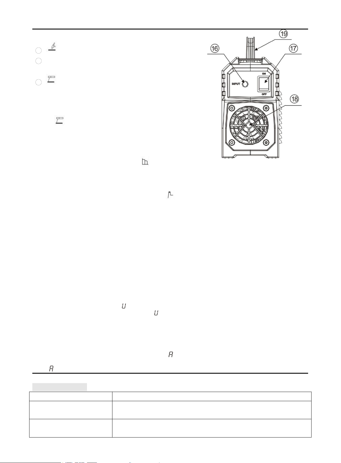
16. Power cord
17. Power switch: Control power.
18.Cooling fan
19.Handle
Combination key for switching VRD on and off:
Welding Mode and Electrode Selection buttons are pressed
simultaneously to switch on or off MMA VRD. Under MMA,
VRD is not available by default, but it is available when
welding Mode and Electrode Selection buttons are pressed
simultaneously for 3S with -1 display. And VRD is
unavailable if press them for 3S again with -0 display.
Combination key for switching anti-stick on and off:
Electrode Selection and Function Mode are pressed
simultaneously to switch on or off MMA anti-stick. Under
MMA, anti-stick function is available by default, but it is
unavailable when Electrode Selection and Function Mode
buttons are pressed simultaneously for 3S with -0display.
And anti-stick function is available if press them for 3S again
with -1display.
Pic 5
Fault code table:
Digital tube display code
Code meaning
E60
overheat protection: machine is under overheat protection and stops
working until E60 disappears
E13
over-current protection:internal components are damaged, please
contact dealer for help

8
Press the key combination to display the code table
Digital tube display code
Code meaning
-0/ -1
-0:Represents no VRD; -1:Representative has VRD
-0/ -1
-0:Represents no anti-stick; -1:Representative has anti-stick
5. INSTALLATION AND OPERATION
Note: Please install the machine strictly according to the following steps.
Turn off the power supply switch before any electric connection operation.
The housing protection grade of this machine is IP21S, so do not use it in rain.
5.1 Installation:
Pic 6 Schematic Diagram of MMA Welding
1) A primary power supply cable is available for this welding machine. Connect the primary power
supply cable to the corresponding voltage class based on rated input power of the welder.
Misconnection should be avoided.
2) The primary cable should be tightly connected to the corresponding power binding post or socket
to avoid oxidization.
3) Check whether the input voltage value varies in acceptable range with a multi-meter.
4) Insert the cable plug with electrode holder into the “+” socket on the front panel of the welding
machine, and tighten it clockwise.
5) Insert the cable plug with ground clamp into the “ -” socket on the front panel of the welding
machine, and tighten it clockwise.
6) Connect the power ground well.
The connection as mentioned above in 4) and 5) is DCRP connection. Operator can choose DCSP
connection according to workpiece and electrode application requirement. Generally, DCRP connection
is recommended for basic electrode (electrode is connected to positive pole), while there is no special
requirement for acid electrode.

9
5.2 Strap Installation
Step 1: Separate the velcro.
Step 2: Pull out one side through the strap hole
on the front panel with hook side of the velcro
up.
Step 3: Pull out it to well stick hook side of the
velcro to loop side and across the nylon buckle.
Repeat it on the other side.
Step 4: Adjust the length by pulling the nylon
buckle (as shown in the picture).
Step 5: Proper state after installation:
1. Strap does not twist;
2. Buckle side of shoulder pad is up, while its
flat side faces the machine (as shown in the
picture);
3. Straps are well locked.

10
The following operation requires sufficient professional knowledge on
electric aspect and comprehensive safety knowledge. Operators should be
holders of valid qualification certificates which can prove their skills and
knowledge. Make sure the input cable of the machine is disconnected from
the electricity utility before uncovering the welding machine.
5.3 Operation
1) After being installed according to the above method, and the power switch being switched on, the
machine is started with the power LED on and the fan working.
2) Pay attention to the polarity when connecting. There are two connection modes for DC welder in
general, one of which is straight polarity in which electrode holder is connected to negative pole and
workpiece is connected to positive pole, the other is reverse polarity to which is opposite.
Phenomena such as unstable arc, spatter, and electrode sticking could happen if improper mode is
selected. Exchange the quick plug to change the polarity if necessary.
3) Select cable with larger cross-section to reduce the voltage drop if the secondary cables (welding
cable and earth cable) are long and distance between workpiece and welder is far.
Preset the welding current according to the type and size of the electrode, clip the electrode and then
welding can be carried out by short circuit arc ignition. For welding parameters, please refer to the below
table.
5.4 Welding parameters table(for reference only)
Electrode
Diameter(mm)
Recommended Welding
Current(A)
Recommended welding
voltage(V)
1.6
30~70
21.2~22.8
2.0
40~90
21.6~23.6
2.5
50~100
22~24
3.2
70~150
22.8~26
4.0
140~180
25.6~27.2
5.0
160~200
26.4~28
Note: This table is suitable for mild steel welding. For other materials, consult related materials
and welding process for reference.
6.TROUBLESHOOTING

11
1) Common Malfunction Analysis and Solution:
Malfunction
Phenomena
Causes and Solutions
Turn on the machine, the
power indicator is off, the
fan doesn't work, and no
welding output.
1) Check if the power switch is closed.
2) Make sure there is power for input cable.
Turn on the machine, the
fan works, but the output
current is unstable and
can't be controlled by
potentiometer when
welding.
1) The current potentiometer fails. Replace it.
2) Check if any loose contact exists inside the machine, especially
connector, etc. If any, check.
Turn on the machine, the
power indicator is on, the
fan works, but no
welding output.
1) Check if any poor contact exists inside the machine.
2) Open circuit or poor contact occurs at the joint of output terminal.
3) The abnormity indicator is on.
A. The machine is under over-heating protection status due to long
time operation. For this situation, it is unnecessary to unplug the
power plug so that cooling fan can continue to cool down the
welder. Welding can be continued after indicator is off;
B. Check if the thermal switch is ok. Replace it if damaged.
C. Check if the thermal switch connection is under good contact.
D. It is possible for welder to be under over-current protection status
if indicator is on for a long time. For this situation, please do not
restart the machine, but contact local agent for professional
assistance.
The electrode holder
becomes very hot.
The rated current of the electrode holder is lower than its actual working
current. Replace it with a bigger rated current.
Excessive spatter in
MMA welding.
The output polarity connection is incorrect. Exchange the polarity.

12
The following operation requires sufficient professional knowledge on
electric aspect and comprehensive safety knowledge. Operators should be
holders of valid qualification certificates which can prove their skills and
knowledge. Make sure the input cable of the machine is disconnected from
the electricity utility before uncovering the welding machine.
7. MAINTENANCE
1) Check periodically whether inner circuit connection is in good condition, connector is fastened (esp.
plugs or components). Tighten the loose connection. If there is oxidization, remove it with
sandpaper and then reconnect.
2) Keep hands, hair and tools away from the charged parts such as the fan to avoid personal injury or
machine damage when the machine is energized.
3) Clean the dust periodically with dry and clean compressed air. If welding environment with heavy
smoke and pollution, the machine should be cleaned daily. The pressure of compressed air should
be at a proper level in order to avoid the small parts inside the machine being damaged.
4) Avoid water and vapor infiltrating the machine. If there is, dry it and use tramegger to check the
insulation of the equipment (including that between the connections and that between the
connection and the enclosure). Only when there are no abnormal phenomena anymore, can the
machine be used.
5) Check periodically whether the insulation cover of all cables is in good condition. If there is any
dilapidation, rewrap it or replace it.
6) Put the machine into the original packing in dry location if it is not to be used for a long time.
8. SYMBOL EXPLANATION
Matters to be noticed in operation
Objects to be specially described and
pointed out
It is prohibited to dispose the electrical
waste together with other common
wastes. Please protect the
environment.
This manual suits for next models
1
Table of contents
Other ARCCAPTAIN Welding System manuals
Popular Welding System manuals by other brands

Craftsman
Craftsman 117.205710 Operator's manual

Magmaweld
Magmaweld ID 300 MW user manual

Miller
Miller Big Blue 300 PRO Series owner's manual

Red-D-Arc Welderentals
Red-D-Arc Welderentals DX350 Operator's manual

Lincoln Electric
Lincoln Electric INVERTEC V155-S 11327 Operator's manual

HBS
HBS C 08 operating manual