Omnicomm LLS-Ex 5 Fuel Level Sensor and
BIS-MX Intrinsic Safety Unit
General Information
This User Manual is designed for Omnicomm LLS-Ex 5 fuel level sensor and BIS-MX
Intrinsic Safety Unit.
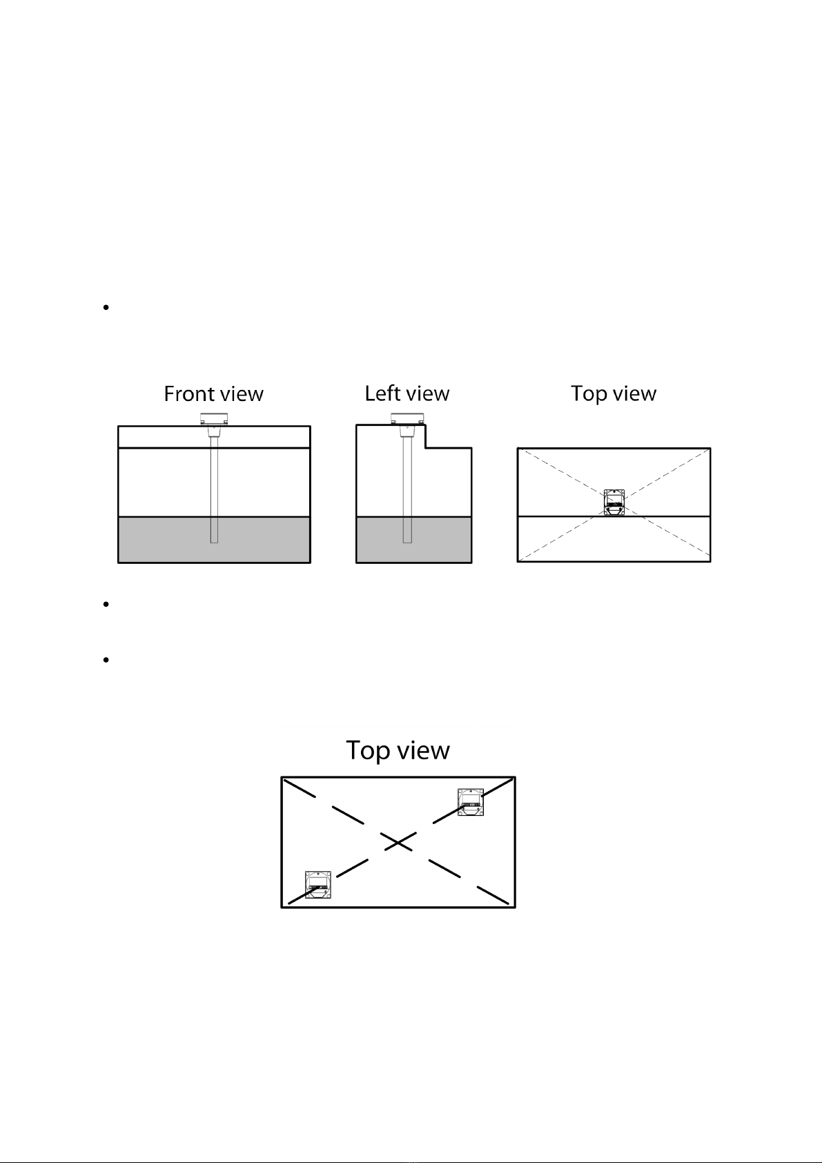
Omnicomm LLS-Ex 5 sensor
Omnicomm LLS-Ex 5 fuel level sensors are designed to measure fuel level in tanks of
vehicles and stationary fuel storages.
Fuel level sensors also measure the temperature. RS-485 or RS-232 interfaces are used to
exchange information with the device.
The Omnicomm LLS-Ex 5 fuel level sensor is installed on special types of equipment or on
stationary fuel tanks and storages, which require equipment explosion protection and
have the “0ExiaIIBT6X” explosion protection label.
The sensor calibration is adjusted automatically when fuel composition or properties
change.
The types of fuel in which the sensor can operate: gasoline, summer fuel and winter
diesel fuel and other liquid light petroleum products.
Different versions of Omnicomm LLS-Ex 5 are available depending on the length of the
measuring probe: 700 mm, 1000 mm, 1500 mm, 2000 mm, 2500 mm, 3000 mm. Any
measuring probe longer than 3000 mm is composite.
The Omnicomm LLS-Ex 5 fuel level sensor is installed together with the BIS-MX spark
protection unit manufactured by Omnicomm.
BIS-MX Intrinsic Safety Unit
BIS-MX intrinsic safety unit on voltage regulation tubes is designed to protect intrinsically
safe circuits when exposed to a voltage of up to 250 V.
BIS-MX is designed to be located outside of the hazardous area.
BIS-MX is designed for installation in electrical circuits connecting Omnicomm LLS-Ex 5


