OmniCure S2000 Elite User manual

035-00708R R0
Excelitas Canada Inc.
2260 Argentia Road, Mississauga ON L5N 6H7
Tel: 1-905-821-2600
Toll Free: 1-800-668-8752
www.excelitas.com/omnicure
Installing the Light Guide
1. Remove the protective end caps from the light guide.
2. Insert the light guide into the light guide port on the front panel until
itsets with a positive click.
Note: When power to the unit is turned on and system is
initialized, the light ring will change colors indicating the following states:
Red: Light Guide not detected
Blue: Light Guide inserted –System warming up
Magenta: Light Guide inserted –Closed-Loop Feedback Inactive
Yellow: Light Guide inserted –Closed-Loop Feedback Active, Calibration close to expiration
Green: Light Guide inserted –Closed-Loop Feedback Active
Start up
1. With the OmniCure®S2000 Elite system not connected to power, install the lamp module (See Page 3).
2. Install the Optical band pass filter (See Page 4).
3. Plug the unit into a properly grounded AC outlet.
4. Turn on the Power switch at the back of the unit.
5. The light ring will light up when power is turned on to the system, followed by the screen initializing a few
seconds later. The lamp will not strike at startup on Demo systems by default (this can be changed in
the Settings –Default Lamp state).
Note: If the Default Lamp state setting has been modified to ON, the lamp will strike at start-up. Allow
the lamp to warm-up uninterrupted, DO NOT TURN SYSTEM OFF while the lamp is warming up!
Using the OmniCure S2000 Elite
1. Following the initialization period, the OmniCure S2000 Elite will display
3 main options on the Home screen: Information, Run and Settings.
2. Information and Settings can be accessed while the lamp is turned off.
3. To start running exposures, press the Lamp icon to strike the
lamp. Allow the lamp to warm-up (Excelitas recommends 20 minutes of
proper warm-up to ensure stable optical output). During the warm-up
period, the screen will indicate the minimum warm-up count-down.
Warning: UV light and elevated levels of visible light will be emitted from the end of the light guide.
S2000 Elite –Quick Start Guide
Warning –Refer to Safety Precautions Booklet 035-00636R prior to use
User Guide 035-00707R: https://www.excelitas.com/product/omnicure-s2000-Elite-spot-uv-curing-system

035-00708R R1
2
Running Exposures
1. Enter the RUN screen by touching the icon on the LCD screen.
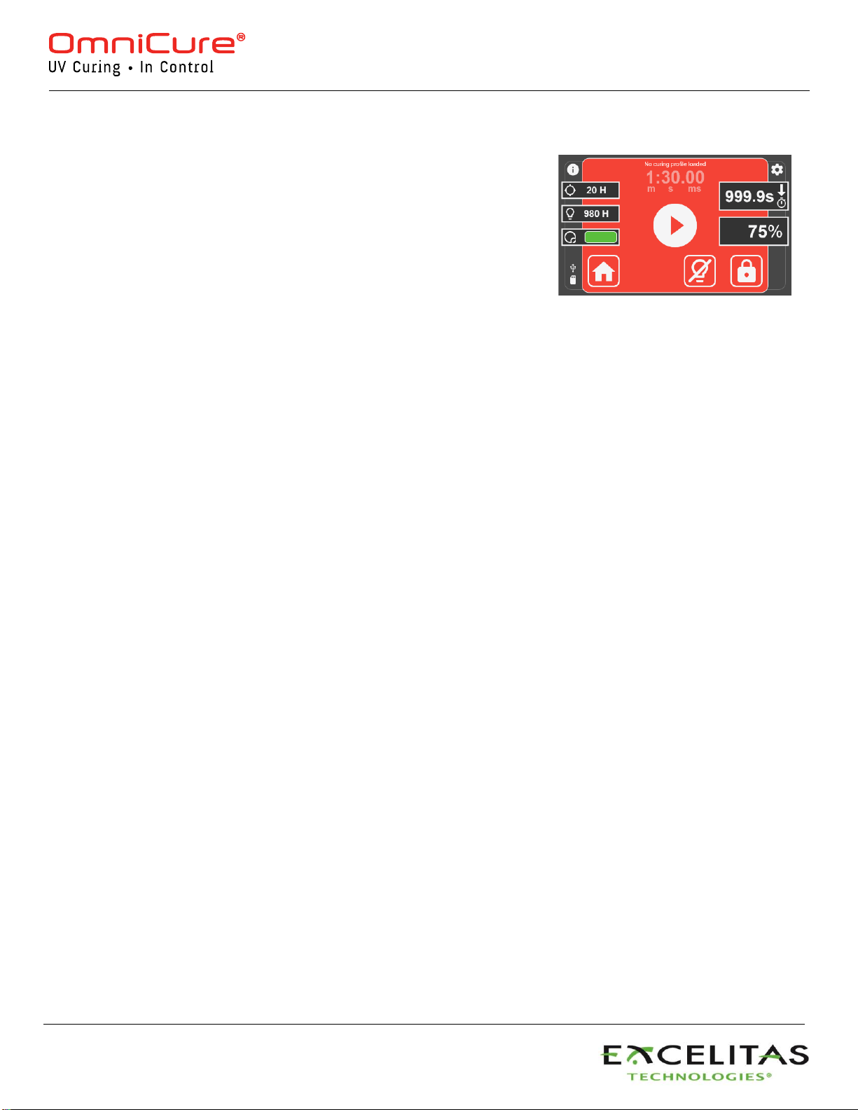
2. Exposures can be started by the START/STOP switch or bytouching
PLAY on the screen.
3. Exposures can be PAUSED and RESUMED until count down timer
has run out. For count up timer, pausing and resuming can be done
indefinitely.
4. To reset an exposure, it is necessary to PAUSE the exposure and
touch the RESET icon. If count down timer has run out, the exposure
will reset automatically.
5. You can exit to the HOME screen at any time as long as an exposure
is not running (stopped or paused).
Setting the Exposure Time
1. Use the LEFT or RIGHT navigation buttons to change timer when in the Run screen.
2. Or press the timer window on touch screen and enter desired count down time on number pad.
3. Set value to 0 to set Count Up timer.
Setting the Intensity Level
1. Use the UP or DOWN navigation buttons to set intensity.
2. Or press the intensity window on touch screen and enter desired intensity on the number pad.
3. Calibration needs to be performed to enable intensity control in W/cm2and W.
Locking and Unlocking the System
1. On the RUN screen, select the LOCK icon and enter the PIN to lock the system (Default PIN is 1234)
2. When the system is locked, the user cannot exit the screen or change any of the exposure settings. The user
can only initiate, stop, or reset the exposure using the Start/Stop button, Play Icon, or Foot Pedal. If running a
StepCure®profile, user can only initiate, stop, or reset the exposure with the pre-defined inputs.
3. To unlock the system, select the UNLOCK icon and enter the PIN (Default PIN is 1234).
Note: The PIN can be changed by navigating to Settings Advanced Setup Screen Lock Pin.
Using the Foot Pedal / Remote Device (Rear Panel: 3.5mm Jack)
Depressing the foot pedal, or providing a momentary contact closure, provides the same function as pressing the
start/stop button. The shutter opens as per the current mode (Intensity or Timer) of the unit.

035-00708R R1
3
1. Ensure the AC power cord is disconnected from the unit.
2. Remove the screws from the lamp access side panel using the tool (3mm
allen key) provided and remove the panel from the unit cover.
3. Carefully remove the lamp module from its container, holding only the
ceramic component and glass rim.
Warning: Wear ESD protective equipment when handling the lamp
and avoid touching the circuit board.
4. As illustrated, position the lamp facing towards the front of the unit with the
power leads facing towards you.
Caution: Do not touch the bulb’s glass envelope or the inside
surface of the reflector. Skin oils can cause the lamp module to fail
prematurely.
5. Make sure the middle of the lamp is in position to fit into the spring clamp.
Slide the lamp until it snaps into the spring clamp. The leading edge of the
reflector should fit snugly into the lamp holder recess.
6. Locate the 6-pin Intelli-Lamp®sensor connector at the rear of the lamp
module and connect it to its mate located behind the the lamp- housing
wall.
Tip: the Intelli-lamp connector will only attach in the correct orientation. If
you are having difficulty attaching the connector, try rotating it by 180º.
7. Tuck the Intelli-Lamp wires into the grommet located on the divider wall
between the lamp and the connector.
Waring: Failure to do so will result in the door not fully closing and
system will not power on.
8. Locate the Power connector with two leads and connect it to its mate
located on the bottom of the lamp-housing wall.
Tip: The Lamp Power connector will only attach in the correct orientation.
If you are having difficulty inserting the connector, try rotating it by 180º.
9. It is very important to ensure that the lamp anode cooling fin (bar) and
lamp power lead, at the front of the lamp are centered within the lamp
holder cutout. Rotate the lamp as required.
10. Replace the lamp housing side panel and tighten the fastening screws.
Warning: If the lamp housing panel is not secured completely, the
unit will not power on.
Installing the Lamp Module
The OmniCure S2000 Elite curing system is available with the choice of two different lamps. UV1 standard curing
lamp and UV3 Surface curing lamp. Choose the appropriate type of lamp for your curing needs:
Warning: Exposure to Mercury represents a health hazard to humans. When unpacking or installing the
lamp, always wear protective clothing and a facemask.

035-00708R R1
4
Installing the Optical Filter
The OmniCure S2000 Elite curing system is equipped with user-changeable optical filters cartridges.
Seven different filter options are available to choose from:
400-500nm, 365nm, 320-390nm, 250-450nm, 320-500nm, no filter and customer filter.
Choose the appropriate optical filter for your curing needs:
1. Ensure the AC power cord is disconnected from the unit.
2. Remove the screws from the lamp access side panel using the
tool (3mm allen) provided and remove the panel from the unit cover.
3. Carefully remove the filter cartridge from its packaging and insert into
the slot with the filter’s model number tag pointing towards the lamp.
4. Secure the filter to the system using the provided M4 screws using
the 3mm allen key.
Note: If the filter is removed and not replaced with another filter,
it is recommended to fasten the screws back into the system
until another filter is installed at another time. This will prevent
the screws from being lost.
5. Replace the lamp housing side panel and tighten the fastening screws.
6. Reconnect the AC power cord and turn on the Power switch at the back of
the unit to turn the system ON.
Note: If the filter is properly installed, the system will automatically recognize the type.
It will be shown in the “Information” section of the GUI.
Warning: If the filter is not properly installed or fastened, the filter will not be
recognized, and the lamp will not strike
Regulatory Information
Product Safety and Electromagnetic Compatibility
The OmniCure S2000 has been tested and found to comply with product safety and electromagnetic
compatibility requirements. For a complete list of tests and for certification details, please contact
your OmniCure representative or refer to the User Guide.
Council Directive 2014/35/EU
Low Voltage Directive
Council Directive 2014/30/EU
EMC Directive
Council Directive 2012/19/EU
WEEE Directive
Council Directive 2011/65/EU as amended by (EU) 2015/863
RoHS
Council Directive 2014/53/EU
Radio Equipment
FCC ID: 2AXSI-SSERIES
IC ID: 26590-SSERIES
WEEE Directive China RoHS CE Marking
Table of contents
Other OmniCure Industrial Equipment manuals