4
Step 3b — Mounting to Concrete/Masonry
The wall plate can mounted directly to concrete/masonry walls.
Remove the tape strip from the back of the template, and place the template in the
desired location. Using a bubble level, hold the template in a level position and then press the adhesive backing against
the wall to hold the guide in place.
Note: Depending upon the roughness of the surface, you may need to hold the template in place with an additional appli-
cation of tape or blue painter’s tape.
Using a 1/2” (13 mm) masonry drill bit, drill 6 mounting holes 3 1/8” (80 mm) deep into the concrete/masonry surface.
Drill through the mounting hole cut-out sections of the template.
Note: For best results from the dust channel, press and hold the template against the wall about 2” (50 mm) from where
you are drilling.
Carefully remove the guide from the wall, and discard. Note: Be sure to hold the guide in an upright position so as not to
spill the collected dust.
Insert wall anchors into the mounting holes, and lightly tap them flush to the wall with a hammer. (Fig. 3)
WARNING
• NEVER drill into mortar joints!
• Concrete must be 2000 PSI density minimum.
IMPORTANT
Masonry anchors MUST be seated firmly against the concrete or masonry. If mounting to a masonry wall covered with drywall/
plaster, counter bore a hole through the drywall/plaster around the mounting hole location, so that the anchor can be seated di-
rectly against the concrete or masonry.
Fig. 3
Step 3c — Mounting to Cinder Block
The wall plate can mounted directly to cinder block walls.
Remove the tape strip from the back of the template. Using a bubble level, hold the template in a level position and then
press the adhesive backing against the wall to hold the guide in place.
Note: Depending upon the roughness of the surface, you may need to hold the template in place with an additional appli-
cation of tape or blue painter’s tape.
Using a 1/2” (13 mm) drill bit, drill 6 mounting holes 3 1/8” (80 mm) deep into the cinder block surface. Drill through the
mounting hole cut-out sections of the template.
Note: For best results from the dust channel, press and hold the template against the wall about 2” (50 mm) from where
you are drilling.
Carefully remove the guide from the wall, and discard. Note: Be sure to hold the guide in an upright position so as not to
spill the collected dust.
Insert wall anchors into the mounting holes, and lightly tap them flush to the wall with a hammer. (Fig 3)
WARNING
• Cinder Block must meet ASTM C-90 specifications.
• Mount to solid portion of block, generally 1” from the sides.
• NEVER drill into mortar joints!
• Use standard drill set on slow speed/ high torque setting. DO NOT use hammer drill on cinder block.
• Verify that you have a minimum of 1 3/8” of actual concrete thickness in the mounting hole, before inserting the wall anchor.
IMPORTANT
Masonry anchors MUST be seated firmly against the concrete or masonry. If mounting to a wall covered with drywall/plaster, counter bore a
hole through the drywall/plaster around the mounting hole location, so that the anchor can be seated directly against the concrete or masonry.
5
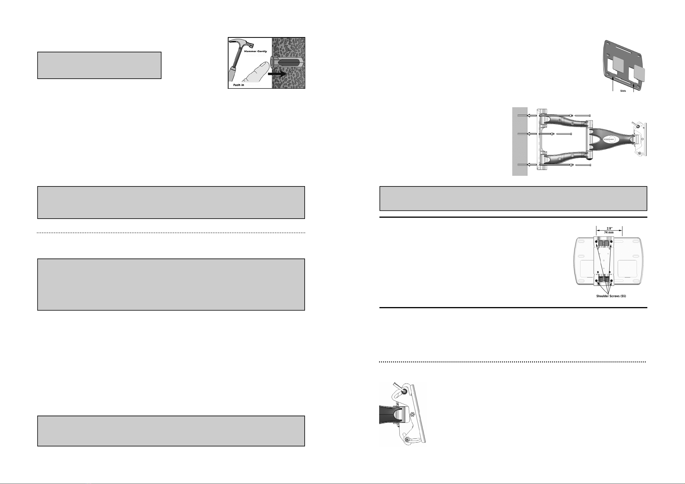
Fig. 4
Step 4 — Mounting to the Wall
Remove the cantilever assembly from the box.
If you have installed electrical boxes into the wall, you will need to remove the Cover Panels from
the wall plate before proceeding. Insert a flat bladed screwdriver into the slots on the bottom of the
plastic cover panels, and carefully pry them from the wall plate. See Fig. 4.
Note: The arm assembly has been removed from Fig. 4 for
clarity. DO NOT remove the arm assembly from the wall
plate prior to mounting the wall plate to the wall.
With the help of an assistant, carefully hold the mount in
position over the mounting holes, and then securely bolt the
wall plate to the wall with supplied spacers (1) and 3/8” lag
bolts (2). See Fig 5.
IMPORTANT
Tighten lag bolts so that wall plate is firmly attached to wall, but DO NOT over tighten. The Lag bolts can be damaged by over tightening,
which greatly reduces their holding power. Final tightening of lag should always be done by hand, with a ratchet wrench and socket.
Fig. 6
Step 5 — Adjusting Lateral Arm Position
Once mounted, the lateral position of the arm assembly can be adjusted left or right by
sliding it across the wall plate. The total range of adjustment is 2.9” (74 mm), as
shown in Fig. 6.
To move the arm assembly, loosen the four shoulder screws (SS) with the Large sup-
plied hex wrench. Carefully slide the arm assembly into the desired position, and then
securely tighten the shoulder screws.
To attach a flat panel display to the mount, you will need an optional adaptor plate. Follow the instructions included with
the adaptor plate to attach the display.
Step 6 — Attaching the Display
Fig. 5
Fig. 6
CAUTION: WHEN REMOVING THE DISPLAY MAKE SURE THE HEAD IS
LOCKED IN THE NEGATIVE TILT POSITION, OTHERWISE INJURY COULD
OCCUR.
Negative Tilt