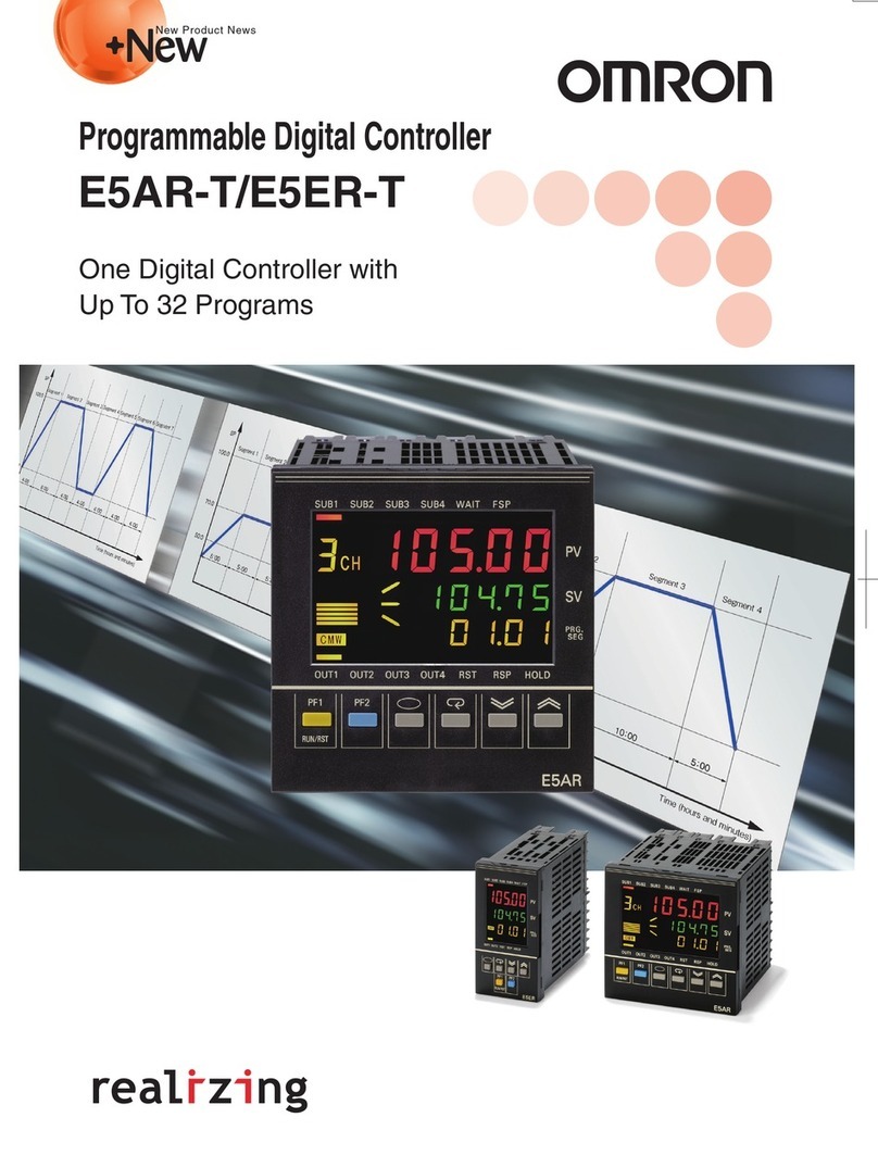
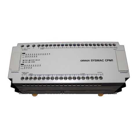
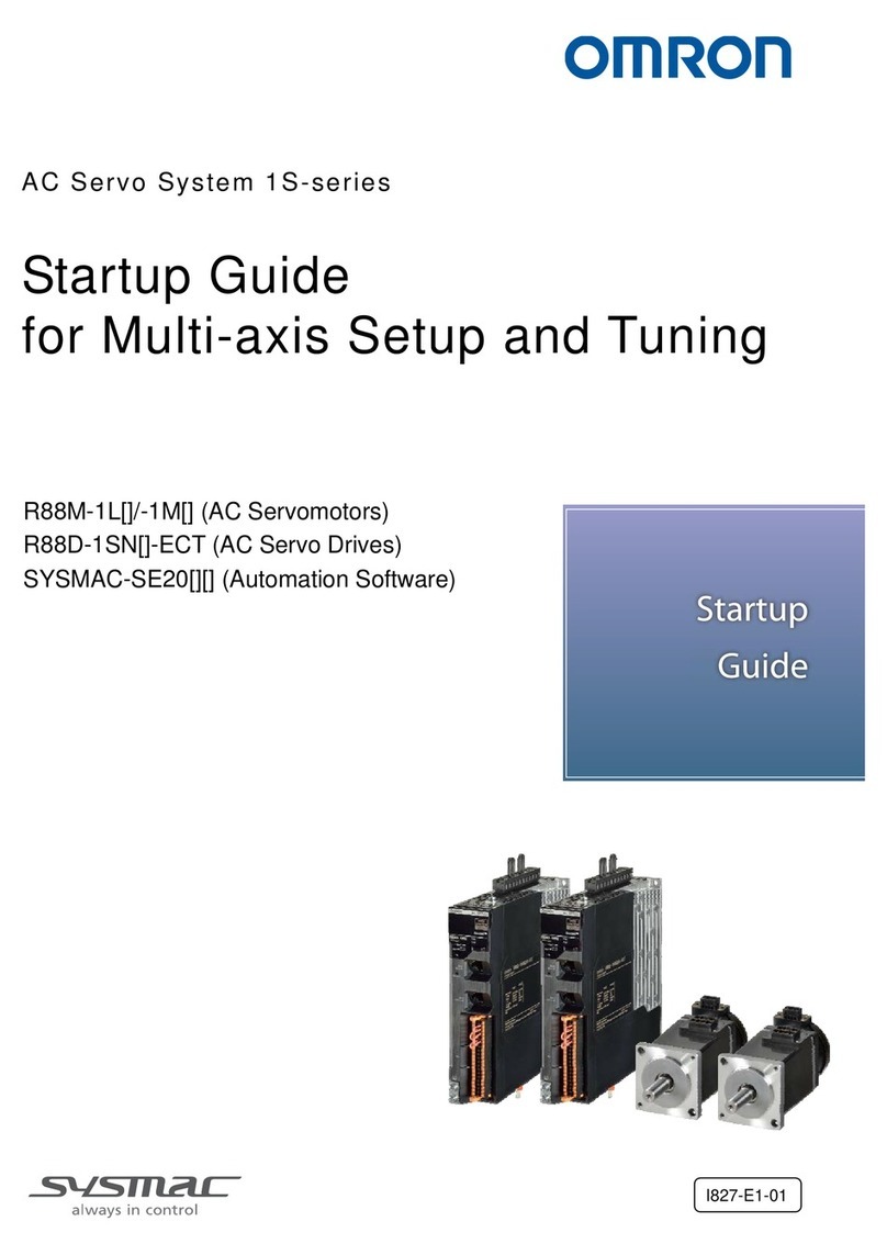
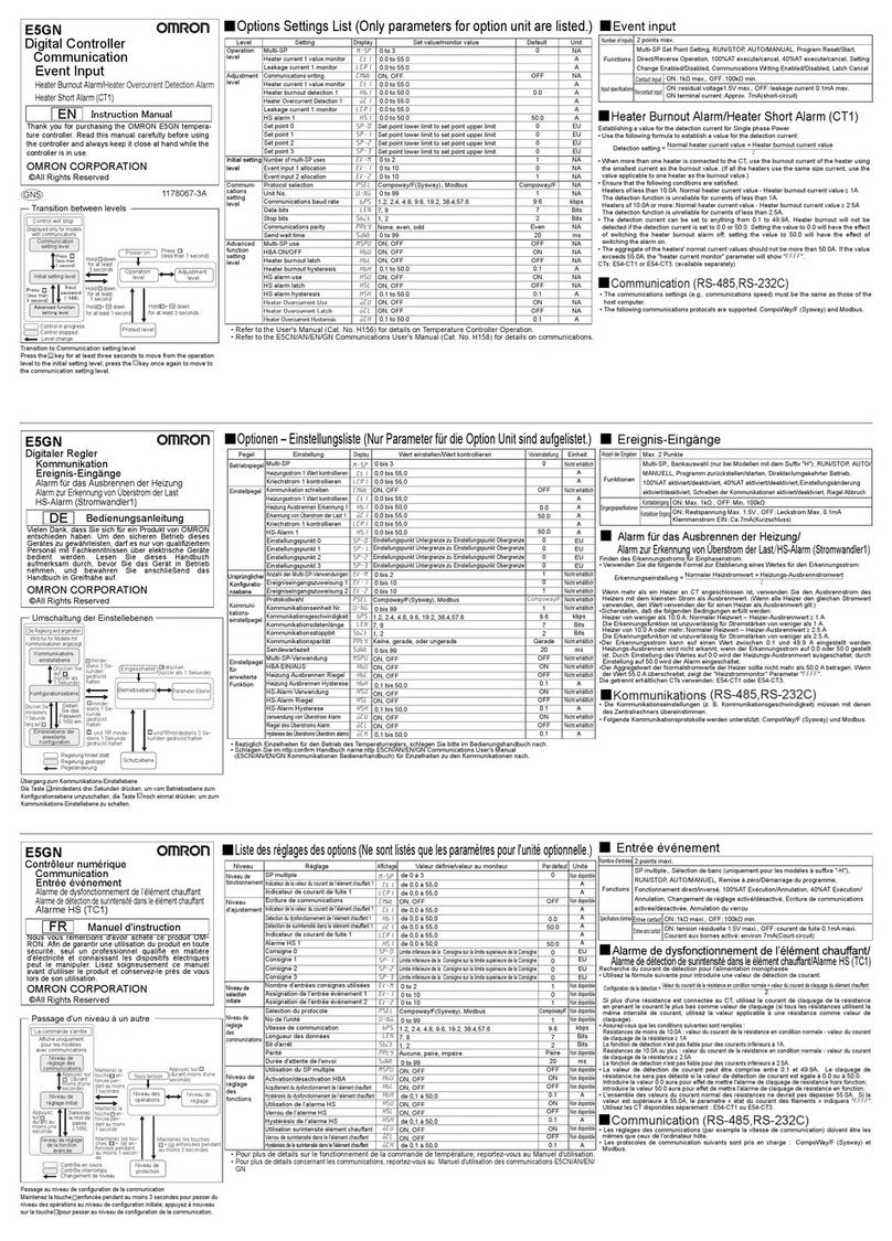
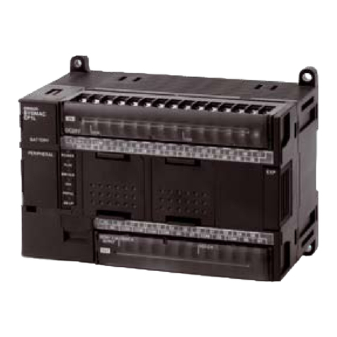
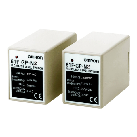
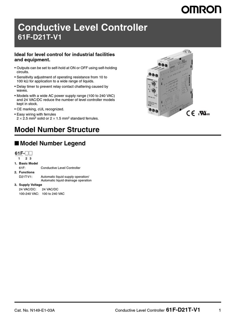
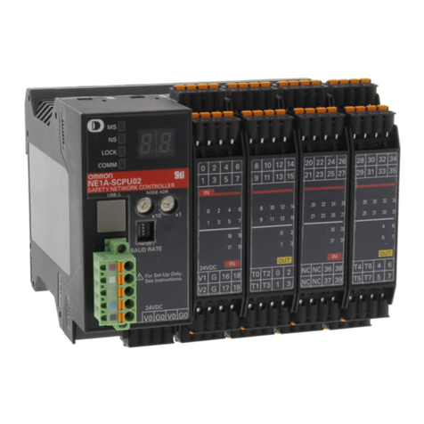
Omron CP2E User manual

Programmable Controller
CP2E
Micro PLC designed to support
data collection and Machine
to Machine communication

2
Diverse range of functions for your machine
Efficient solution for a flexible production, traceability and monitoring of machine key assets,
to respond to operational excellence.
Improved connectivity to networking and serial devices.
Reduced development time with function blocks (FBs) programming.
Battery-free operation increases robustness and reduces maintenance. The extended operating
temperature range increase reliability for special applications.
Note: Please check datasheet (Cat. No. P145) to select your controller. Available functions differ model by model.
2 Ethernet ports 4-axis positioning function
CP2E-N
Up to 3 serial ports

Normal operation continues
-20 to 60℃
1 port
2 ports
3
Install and forget: reliable solution
for all environmental conditions
Input/output terminal
LED indicators for quick
troubleshooting
Automatic Recovery by
electric interferences
* Needed only in case Real Time Clock is used.
Extended operational
temperature range
Battery-free operation*
Improved connectivity
for ethernet and serial devices P.4 -5
Built-in Ethernet switching function
Serial open protocols and Modbus communication
P.7
FB
Reduced effort to realize complex machines
4-axis positioning function with linear interpolation
P.6 -7
Try Omron Function blocks for positioning,
Machine to Machine communication and
predictive maintenance
Download from
www.ia.omron.com/cp_fb

2Ethernet
ports
4
FB
Ethernet Send/Receive Data
Reduce programming time by Ethernet
Send/Receive Data FB to easily
exchange data between controllers.
Improved connectivity for ethernet and serial devices
Ready for Machine to Machine communication
Connect machines to networks to collect field data.
Two built-in Ethernet ports eliminate the need for switching hubs. One port is connected to the host,
and another can be connected to an HMI, PLC, or PC running support software or reserved.
Machine to Machine connectivity
Note: The L2 Switching Hub function is built in.
Two Ethernet ports on the CP2E share the same IP address.
Improve design efficiency and productivity
reducing development time with
a modular conception of the machine
Assembling lines
MES connection
CP2E-N
CP2E-N CP2E-N
Ethernet
Ethernet
NB
Host and HMI connectivity
CP2E-N

Up to
3serial
ports
Up to
3
serial
ports
5
FB Modbus RTU master
Reduce programming time by Modbus FB
to easily communicate with serial devices.
Open connectivity to serial devices
CP2E-N can use up to 3 serial ports by mounting option boards.
Data collection, Control and Monitoring of serial devices is easy and flexible.
Ethernet
RS-232C RS-232C RS-485
Bar code reader
Measurement device
(air leak tester,
weigher, etc.)
Inverter Semiautomatic assembling
machines
CP2E-N NB
Connect bar code readers for traceability
and monitor state of machine
CP2E-N

Ethernet
6
Reduced effort to realize complex machines
Positioning on mark for Packaging Machines
CP2ENB
Operate with 4-axis
simultaneously to reduce
machine cycle time
Pick and Place
Constant movement from
mark detection to seal
position
Packaging machine
Inverter
RS-485
Temperature Sensor
RS-232C
Stop after a defined
amount of pulses
(Time)
Interrupt input
Simplified positioning:
4-axis can operate simultaneously for
a faster positioning.
With one instruction you can
execute a fixed positioning
on Interrupt input (mark)
independently by PLC cycle time.
Interrupt feeding
PID Control with auto tuning
Servomotor/Servo Drive
CP2E-N NB
CP1W-TS003
Temperature Sensor Unit
Speed
control
Position
control
Up to 4-axis linear interpolation CP2E-N
CP2E-N/CP2E-S
4-axis positioning
Instruc-
tion
FB Linear interpolation
Fixed positioning on interrupt
(IFEED instruction)

7
Cost reduction in maintenance,
logistic/stock
Stable multipoint temperature control,
setting via NB series HMI
Small extrusion machine
CP1W-TS004
12-ch Temperature Sensor Unit
CP2E
Pressure/position
Inverter control
Temperature
Sensor
NB
Extended operational temperature range
Increase reliability in special
applications
Temperature Sensor
Battery-free operation*
Automatic Recovery by electric
interferences.
Normal operation continues
CP2E detects and recovers
in real-time operation a bit
corruption.
Increase machine efficiency
avoiding CPU stops.
PID Control with auto tuning
RS-232C
(Time)
(Temperature)
Hunting Overshooting
Temperature
control (PID)
CP1W-MAD44
4 inputs/4 outputs
Analog I/O Unit
Stable temperature control with autotuning function CP2E-N/CP2E-S/CP2E-E
PID with Autotuning function
enable stable temperature
control reducing start-up time.
Connection with stand alone
temperature control is also
available.
Install and forget: reliable solution
for all environmental conditions
Grain storage
facility
Waste disposal
equipment
Multi-level
parking
-20 to 60℃
* Needed only in case Real Time Clock is used.
Reduce installation time
and easily check wiring
errors by LED indicators
I/O LED indicators
CP2E-N/CP2E-S/CP2E-E
FB PID Control with auto tuning

CPU unit with 30, 40, or 60
I/O points
CPU unit with 30, 40, or 60
I/O points
CPU unit with 14 or 20
I/O points
CPU unit with 30, 40, or 60
I/O points
CPU unit with 14 or 20
I/O points
USB port
USB port
Expansion unit
option board
Ethernet
Clock
positioning option board
Ethernet
Expansion unit
positioning option board
Ethernet
Clock
-20 to 60℃Battery-freeClock
Memory
10 K steps
-20 to 60℃Battery-freeClock
3 expansion
units
4-axis
positioning
2option boards
2Ethernet
ports
Memory
10 K steps
Up to
3serial ports
2-axis
positioning
1option board
1Ethernet
port
Up to
2serial ports
USB port
-20 to 60℃Battery-freeClock
Memory
8K steps
1 x RS-232C port
1 x RS-485 port
*1
2-axis
positioning
3 expansion
units
Memory
4K steps USB port
-20 to 60℃Battery-free
1 x RS-232C
port *1
3 expansion
units
1 x RS-232C
port *1
Memory
4K steps USB port
-20 to 60℃Battery-free
8
Network Model: Ethernet connectivity, 4-axis positioning, FB programming
Essential Model: 1 serial port, FB programming
Standard Model: 2 serial ports, 2-axis positioning, FB programming
CP2E-N
CP2E-S
CP2E-E
*1. RS-232C: Screwless terminal block (6 terminals), RS-485: Screwless terminal block (3 terminals)
Product lineup

9
20-point I/O Unit
16-point Output Unit
Analog Input Unit
Analog Output Unit
Analog I/O Unit
12-ch Temperature
Sensor Unit
I/O Connecting Cable
4-ch Temperature
Sensor Unit
2-ch Temperature
Sensor Unit
8-point Input Unit
8-point Output Unit
Battery: only for Real time
Clock function-
CP2E-N/CP2E-S CPU Unit
Option Board (for CP2E-N-type CPU Units)
Expansion I/O Unit and Expansion Unit
Battery
RS-232C
RS-232C
RS-232C
RS-485 (isolated)
RS-485 (isolated)
RS-485 (isolated)
RS-232C RS-422A/485 RS-422A/485
(isolated)
2 analog inputs
0 to 10 V, 0 to 20 mA
2 analog outputs
0 to 10 V
2 analog inputs
0 to 10 V,
0 to 20 mA
2 analog outputs
0 to 10 V
Analog Option Board*2
*2. Two 2-port serial option boards cannot be mounted in a CPU unit.
Two analog option boards also cannot be mounted in a CPU unit.
40-point I/O Unit
32-point Output Unit
2-port Serial Option Board *2
1-port Serial Option Board

10
I/O points Specifications
Power supply Inputs Outputs Output type
Program capacity DM Area capacity
Model
14
100 to 240 VAC
8 6
Relay
10K steps 16K words
CP2E-N14DR-A
Transistor (sinking) CP2E-N14DT-A
24 VDC
Relay CP2E-N14DR-D
Transistor (sinking) CP2E-N14DT-D
Transistor (sourcing) CP2E-N14DT1-D
20
100 to 240 VAC
12 8
Relay CP2E-N20DR-A
Transistor (sinking) CP2E-N20DT-A
24 VDC
Relay CP2E-N20DR-D
Transistor (sinking) CP2E-N20DT-D
Transistor (sourcing) CP2E-N20DT1-D
30
100 to 240 VAC
18 12
Relay CP2E-N30DR-A
Transistor (sinking) CP2E-N30DT-A
24 VDC
Relay CP2E-N30DR-D
Transistor (sinking) CP2E-N30DT-D
Transistor (sourcing) CP2E-N30DT1-D
40
100 to 240 VAC
24 16
Relay CP2E-N40DR-A
Transistor (sinking) CP2E-N40DT-A
24 VDC
Relay CP2E-N40DR-D
Transistor (sinking) CP2E-N40DT-D
Transistor (sourcing) CP2E-N40DT1-D
60
100 to 240 VAC
36 24
Relay CP2E-N60DR-A
Transistor (sinking) CP2E-N60DT-A
24 VDC
Relay CP2E-N60DR-D
Transistor (sinking) CP2E-N60DT-D
Transistor (sourcing) CP2E-N60DT1-D
I/O points Specifications
Power supply Inputs Outputs Output type
Program capacity DM Area capacity
Model
30
100 to 240 VAC
18 12
Relay
8K steps 8K words
CP2E-S30DR-A
24 VDC
Transistor (sinking) CP2E-S30DT-D
Transistor (sourcing) CP2E-S30DT1-D
40
100 to 240 VAC
24 16
Relay CP2E-S40DR-A
24 VDC
Transistor (sinking) CP2E-S40DT-D
Transistor (sourcing) CP2E-S40DT1-D
60
100 to 240 VAC
36 24
Relay CP2E-S60DR-A
24 VDC
Transistor (sinking) CP2E-S60DT-D
Transistor (sourcing) CP2E-S60DT1-D
I/O points Specifications
Power supply Inputs Outputs Output type
Program capacity DM Area capacity
Model
14
100 to 240 VAC
86Relay
4K steps 4K words
CP2E-E14DR-A
20 12 8Relay CP2E-E20DR-A
30 18 12 Relay CP2E-E30DR-A
40 24 16 Relay CP2E-E40DR-A
60 36 24 Relay CP2E-E60DR-A
Ordering Information
CP2E-N/Network Models
CP2E-S/Standard Models
CP2E-E/Essential Models
CPU Units
Function Blocks are available to download free of charge from Omron website. (www.ia.omron.com/cp_fb)
FB
For details, refer to datasheet of CP2E (Cat.No. P145).

11
Product name Specifications Model
1-port Serial Option Board
RS-232C CP1W-CIF01
RS-422A/485 CP1W-CIF11
RS-422A/485 (isolated) CP1W-CIF12-V1
2-port Serial Option Board *1
RS-232C 2port CP2W-CIFD1
RS-232C, RS-485 (isolated) CP2W-CIFD2
RS-485 (isolated) 2port CP2W-CIFD3
Analog Option Board *1
2 analog inputs. 0 to 10 V (resolution: 1/4000), 0 to 20 mA (resolution: 1/2000) CP1W-ADB21
2 analog outputs. 0 to 10 V (resolution: 1/4000) CP1W-DAB21V
2 analog inputs. 0 to 10 V (resolution: 1/4000), 0 to 20 mA (resolution: 1/2000)
2 analog outputs. 0 to 10 V (resolution: 1/4000) CP1W-MAB221
Product name Specifications
License
Media Model
CX-One Lite Ver4.□A subset of the complete CX-One package that provides
only the support software required for compact PLC applications 1 DVD CXONE-LT01D-V4
Cx-One Ver4.□A comprehensive software package that integrates support software
for Omron PLCs and components 1 DVD CXONE-AL01D-V4
Unit type Product name
Inputs Outputs
Specifications Model
CP1W
Expansion
I/O Unit
Input Unit 8 -24 VDC input CP1W-8ED
Output Unit -
8 Relay CP1W-8ER
8 Transistor (sinking) CP1W-8ET
8 Transistor (sourcing) CP1W-8ET1
16 Relay CP1W-16ER
16 Transistor (sinking) CP1W-16ET
16 Transistor (sourcing) CP1W-16ET1
32 Relay CP1W-32ER
32 Transistor (sinking) CP1W-32ET
32 Transistor (sourcing) CP1W-32ET1
I/O Unit
12 8 Relay CP1W-20EDR1
12 8 Transistor (sinking) CP1W-20EDT
12 8 Transistor (sourcing) CP1W-20EDT1
24 16 Relay CP1W-40EDR
24 16 Transistor (sinking) CP1W-40EDT
24 16 Transistor (sourcing) CP1W-40EDT1
CP1W
Expansion
Unit
Analog
Input Unit
4 ch
-
Input range: 0 to 5 V, 1 to 5 V, 0 to 10 V, -10 to 10 V,
0 to 20 mA, or 4 to 20 mA. Resolution: 1/6000 CP1W-AD041
4 ch Input range: 0 to 5 V, 1 to 5 V, 0 to 10 V, -10 to 10 V,
0 to 20 mA, or 4 to 20 mA. Resolution: 1/12000 CP1W-AD042
Analog Output
Unit -
2 ch Output range: 1 to 5 V, 0 to 10 V, -10 to 10 V,
0 to 20 mA, or 4 to 20 mA. Resolution: 1/6000
CP1W-DA021
4 ch CP1W-DA041
4 ch Output range: 1 to 5 V, 0 to 10 V, -10 to 10 V,
0 to 20 mA, or 4 to 20 mA. Resolution: 1/12000 CP1W-DA042
Analog
I/O Unit
2 ch 1 ch
Input range: 0 to 5 V, 1 to 5 V, 0 to 10 V, -10 to 10 V, 0 to 20 mA, or 4 to 20 mA.
Output range: 1 to 5 V, 0 to 10 V, -10 to 10 V, 0 to 20 mA, or 4 to 20 mA. Resolution: 1/6000
CP1W-MAD11
4 ch 2 ch
Input range: 0 to 5 V, 1 to 5 V, 0 to 10 V, -10 to 10 V, 0 to 20 mA, or 4 to 20 mA.
Output range: 1 to 5 V, 0 to 10 V, -10 to 10 V, 0 to 20 mA, or 4 to 20 mA. Resolution: 1/12000
CP1W-MAD42
4 ch 4 ch CP1W-MAD44
Temperature
Sensor Unit
2 ch
-
Sensor type: Thermocouple (K or J) CP1W-TS001
4 ch CP1W-TS002
2 ch Sensor type: Platinum resistance thermometer (Pt100 or JPt100) CP1W-TS101
4 ch CP1W-TS102
4 ch Sensor type: Thermocouple (K or J). 4 ch or 2 analog inputs.
Input range: 0 to 10 V, 1 to 5 V, or 4 to 20 mA. Resolution: 1/12000 CP1W-TS003
12 ch Sensor type: Thermocouple (K or J) CP1W-TS004
I/O Connecting Cable 800 mm extension cable for CP1W Expansion I/O Units and CP1W Expansion Units.
Only one I/O Connecting Cable can be used in each PLC CP1W-CN811
Software
*1.Two 2-port serial option boards cannot be mounted in a CPU unit. Two analog option boards also cannot be mounted in a CPU unit.
Product name Specifications Model
Battery CP2E-N, CP2E-S dedicated battery. Install when using the clock function CP2W-BAT02
Battery: only for Real time Clock function- CP2E-N/CP2E-S CPU Unit
Option Boards for CP2E-N
Optional Products
Expansion I/O Units and Expansion Units

・The product photographs and gures that are used in this catalog may vary somewhat from the actual products.
・Some images are used under license from Shutterstock.com.
OMRON Corporation Industrial Automation Company
Note: Do not use this document to operate the Unit.
Regional Headquarters
OMRON EUROPE B.V.
Wegalaan 67-69, 2132 JD Hoofddorp
The Netherlands
Tel: (31)2356-81-300/Fax: (31)2356-81-388
OMRON ASIA PACIFIC PTE. LTD.
No. 438A Alexandra Road # 05-05/08 (Lobby 2),
Alexandra Technopark,
Singapore 119967
Tel: (65) 6835-3011/Fax: (65) 6835-2711
OMRON ELECTRONICS LLC
2895 Greenspoint Parkway, Suite 200
Hoffman Estates, IL 60169 U.S.A.
Tel: (1) 847-843-7900/Fax: (1) 847-843-7787
OMRON (CHINA) CO., LTD.
Room 2211, Bank of China Tower,
200 Yin Cheng Zhong Road,
PuDong New Area, Shanghai, 200120, China
Tel: (86) 21-5037-2222/Fax: (86) 21-5037-2200
Kyoto, JAPAN
Contact: www.ia.omron.com
Authorized Distributor:
© OMRON Corporation 2019 All Rights Reserved.
In the interest of product improvement,
specicationsaresubjecttochangewithoutnotice.
CSM_1_1_0919
Cat. No. P144-E1-01 0919(0919)

CSM_ZEN_DS_E_5_4
1
Programmable Relay
ZEN V2 Units
Even Broader Applications with Increased
Functionality and Higher Precision
• Increased functionality in a compact body (70 mm wide ×90 mm
high).
• Easy programming is available using the LCD and operation
buttons. (See note 1.)
• This single Unit easily provides relay, timer, counter, and time
switch functions.
• Expansion is easy with Expansion I/O Units, allowing up to 44
I/O points. (See note 2.)
• Economy-type and Communications-type CPU Units have been
added to series.
• Improved Weekly Timers (See note 1.)
Increased timing accuracy with a monthly deviation of ±15 s
max. Multiple-day operation and pulse output operation have
been added.
• Select from two power supply options:
100 to 240 VAC or 12 to 24 VDC.
Note: 1. Not supported for ZEN-@C2@@-@-V2 models.
2. When using CPU Units with 20 I/O points.
The information in this document applies to V2 Units.
Refer to page 28 for details on differences with previous
products.
Refer to Safety Precautions on page 33
Features
■Easy and Simple Programming for Automatic Small-scale Control
Saves Space, Wiring, and Installation Steps
•Versatile functionality in a compact body (70 mm wide ×90 mm
high).
•This single Unit easily provides relay, timer, counter, and time
switch functions. Wiring work is greatly reduced because separate
wiring is not required for devices such as timers and counters.
Easy Programming
The LCD screen comes with 8 operation buttons on the front panel to
enable programming in ladder view format. The LCD screen also has
a backlight, making it easier to see when the ZEN is used in dark
locations.
Note: Not supported for ZEN-@C2@@-@-V2 models.
90 mm
70 mm

ZEN V2 Units
2
Flexible Expansion Enables Up to 44 I/O
Points
Up to three Expansion I/O Units can be connected if there are not
enough I/O points. Expansion I/O Units are only 35 mm wide.
Note: CPU Units with 10 I/O points can be expanded to 34 I/O points.
Expansion I/O Units cannot be connected to Economy-type
CPU Units.
Support Software with Simulation Function
•Programs can be easily written, saved, and monitored by personal
computer.
•Programs can be simulated on the personal computer without
connecting to the ZEN.
Note: For notebook computers that do not have an RS-232C serial
port, connect the computer to the ZEN by connecting an
OMRON CS1W-CIF31 USB-Serial Conversion Cable to the
ZEN-CIF01 Connecting Cable.
Other Versatile Functions
•Use of a Memory Cassette makes it easy to copy and save
programs.
•Equipped with two analog input channels (CPU Units with DC
power supply only).
•Password function ensures security. (See note.)
•Multi-language display in six languages (English, Japanese,
German, French, Spanish, Italian). (See note.)
•Display user-set messages or analog-converted values. (See note.)
Note: Not supported for ZEN-@C2@@-@-V2 models.
■Enhanced Features of V2 CPU Units
Improved Weekly Timer and Calendar Timer
Functions
Note: Not supported for ZEN-@C2@@-@-V2 models.
•The time precision has been increased.
Conventional model: 2-min difference/month
↓
-V2 models: ±15-s difference/month (at 25°C)
•Multiple-day operation and pulse-output operation are now
possible.
•These improved functions are convenient for time-controlled
applications such as lighting and air conditioning control.
Economy-type Added to the Series
•Economy-type CPU Units with a more affordable price have been
added to the series, although Expansion I/O Units cannot be
added.
12 to 24 VDC Line Voltage Operation
Operation is now possible with 12 VDC.
Expansion I/O Units have been reduced to
half-size (35 mm wide).
RS-485 Communications Model Added to
Series
Production line conditions can be remotely monitored by monitoring
the ZEN control status.
More Precise Analog Input
Conventional model: ±10% FS →-V2 models: ±1.5% FS
DC power supply models are equipped with two analog inputs (0 to
10 V). There are four analog comparators. The increased precision
makes it even easier to use the Unit in simple control applications
with voltage, current, temperature, and other analog values.
8-digit Counter, 150-Hz Counter
•An 8-digit counter and 8-digit comparator have been added.
•The maximum count for DC power supply models is 150 Hz.
Twin-timer Operation Added
Twin-timer operation allows you to set ON and OFF times separately,
greatly simplifying intermittent operation.
Lighting control Air conditioning control
Office
Production line

ZEN V2 Units
3
■Series Configuration
CPU Units
Power supply voltage: 100 to 240 VAC, 12 to 24 VDC, Output: Relay, transistor output
With LCD display, operation buttons, and calendar/clock function LED type
10 I/O points
Standard LCD type Economy type Standard LCD type Economy type
Communications type
20 I/O points 10 I/O points 20 I/O points
ZEN-10C1@ZEN-10C3@ZEN-10C4@ZEN-20C1@ZEN-20C3@
ZEN-10C2@
(10 I/O points)
ZEN-20C2@
This CPU Unit has no LCD,
operation buttons, or
calendar/clock function.
Expansion I/O Units
cannot be connected.
Expansion I/O Units
cannot be connected.
RS-485 communications
type.
Expans
i
on I
/O
Un
i
ts
Only 35-mm wide.
4 input, 4 output points
Power
S
upply Un
i
t
Same shape and design as ZEN.
24 VDC, 30 W
S
upport
S
o
f
tware
Allows easy programming and
operation simulation.

ZEN V2 Units
4
Model Number Structure
■Model Number Legend
Note: This model number legend includes combinations that are not available.
Please check List of Models on page 5 for availability.
CPU Units
1. Number of I/O points
10: 6 inputs and 4 outputs (See note.)
20: 12 inputs and 8 outputs
2. Type classifier
1: Standard LCD type with display
2: LED type without display
3: Economy type with display
(Expansion I/O Units cannot be connected.)
4: Communications type with display
3. Input type
A: AC input
D: DC input
4. Output type
R: Relay
T: Transistor
5. Supply voltage
A: AC power supply
D: DC power supply
Note: The Communications-type CPU Unit has 6 inputs and 3 outputs.
Expansion I/O Units
1. Number of I/O points
8: 4 inputs and 4 outputs
2. Unit version classifier
E1: Can connect to V2 CPU Units (See note.)
3. Input type
A: AC input
D: DC input
4. Output type
R: Relay
T: Transistor
Note: Use a ZEN-8E@@/-4E@ to connect to pre-V1 and V1 CPU Units.
ZEN-@C@@@-@-V2
1234 5
ZEN-8E1@@
1234
This data sheet is provided as a guideline for selecting products. Be sure to refer to the following user manuals for application precautions
and other information required for operation before attempting to use the product.
ZEN Operation Manual (Cat. No. Z211)
ZEN Communications Manual (Cat. No. Z212)
ZEN Support Software Operation Manual (Cat. No. Z184-E1-03)
The PDF versions of these manuals can be downloaded from the following website.
ZEN Website http://www.fa.omron.co.jp

ZEN V2 Units
5
Ordering Information
■List of Models
CPU Units and Expansion I/O Units
Note: 1. Programming is not possible using only the CPU in the LED-type CPU Unit. ZEN Support Software or a Memory Cassette is required.
2. Cannot be connected to pre-V1 and V1 CPU Units.
3. The ZEN-8E1AR cannot be connected to a CPU Unit with DC power supply.
4. Product no longer available to order.
Power Supply Unit
Note: Product no longer available to order.
Refer to the ZEN-PA03024 Datasheet (Cat. No. L103) for detailed specifications.
Unit Name No. of
I/O
points
LCD
display
Power supply
voltage
Inputs Outputs Buttons,
calendar,
and clock
Analog
input
Model
CPU
Units
Standard
LCD type
10 Yes 100 to 240 VAC 6 100 to 240 VAC 4 Relays Yes No ZEN-10C1AR-A-V2
12 to 24 VDC 12 to 24 VDC Yes ZEN-10C1DR-D-V2
Transistors ZEN-10C1DT-D-V2
20 100 to 240 VAC 12 100 to 240 VAC 8 Relays No ZEN-20C1AR-A-V2
12 to 24 VDC 12 to 24 VDC Yes ZEN-20C1DR-D-V2
Transistors ZEN-20C1DT-D-V2
LED type
without
display
(See note 1.)
10 No 100 to 240 VAC 6 100 to 240 VAC 4 Relays No No ZEN-10C2AR-A-V2
12 to 24 VDC 12 to 24 VDC Yes ZEN-10C2DR-D-V2
Transistors ZEN-10C2DT-D-V2
20 100 to 240 VAC 12 100 to 240V AC 8 Relays No ZEN-20C2AR-A-V2
12 to 24 VDC 12 to 24 VDC Yes ZEN-20C2DR-D-V2
Transistors ZEN-20C2DT-D-V2
Economy
type
(Expansion
I/O Units
cannot be
connected)
10 Yes 100 to 240 VAC 6 100 to 240 VAC 4 Relays Yes No ZEN-10C3AR-A-V2
12 to 24 VDC 12 to 24 VDC Yes ZEN-10C3DR-D-V2
20 100 to 240 VAC 12 100 to 240 VAC 8 Relays No ZEN-20C3AR-A-V2
12 to 24 VDC 12 to 24 VDC Yes ZEN-20C3DR-D-V2
Communica-
tions type
9 100 to 240 VAC 6 100 to 240 VAC 3 Relays No ZEN-10C4AR-A-V2
12 to 24 VDC 12 to 24 VDC Yes ZEN-10C4DR-D-V2
ZEN Kit Set containing CPU Unit (ZEN-10C1AR-A-V2), Connecting Cable, ZEN Support Software, and manual. ZEN-KIT01-EV4
(See note 4.)
Set containing CPU Unit (ZEN-10C1DR-D-V2), Connecting Cable, ZEN Support Software, and manual. ZEN-KIT02-EV4
(See note 4.)
Expansion I/O Units 8 --- 100 to 240 VAC 4 100 to 240 VAC 4 Relays --- ZEN-8E1AR
(See notes 2, 3.)
12 to 24 VDC 12 to 24 VDC ZEN-8E1DR
(See note 2.)
--- Transistors ZEN-8E1DT
(See note 2.)
Power ratings Input voltage Output voltage Output current Model
30 W 100 to 240 VAC 24 VDC 1.3 A ZEN-PA03024

ZEN V2 Units
6
Accessories (Order Separately)
Note: 1. Memory Cassettes created using a CPU Unit can be read to other CPU Units, regardless of which model is used. Restrictions, apply, however,
to the functions that can be used, depending on the CPU Unit version combination. For details, refer to Memory Cassette and CPU Unit
Combinations on page 31.
2. Standard LCD-type, Economy-type, and Communications-type CPU Units (i.e., excluding ZEN-@C2@@-@-V2 models).
3. LED-type CPU Unit without display (i.e., ZEN-@C2@@-@-V2 models).
Mounting Accessories (Order Separately)
System Configuration
Note: 1. Up to 3 Expansion I/O Units can be connected to any type of CPU Unit except for Economy-type CPU Units. Expansion I/O Units with AC Inputs,
however, cannot be connected to CPU Units with DC Power Supplies.
2. The Connecting Cable and Memory Cassette cannot be connected to the ZEN at the same time.
3. Programs cannot be written to LED-type CPU Units (i.e., ZEN-@C2@@-@-V2 models) without the ZEN Support Software or a Memory Cassette.
Name Specifications Remarks Model
Memory Cassette EEPROM (for data
security and copying)
Enables programs and parameter settings to be saved or copied to another
ZEN. (See note 1.)
ZEN-ME01
LCD-type CPU Unit with
display (See note 2.)
LED-type CPU Unit without
display (See note 3.)
Transfer from ZEN to
Memory
Supported Not supported
Transfer from Memory
Cassette to ZEN
Supported Automatic transfer when
power turned ON
Memory Cassette
initialization
Supported Not supported
Connecting Cable 2 m RS-232C (9-pin D-
sub connector)
For notebook computers that do not have an RS-232C serialport, connect the
computer to the ZEN by connecting an OMRON CS1W-CIF31 USB-Serial
Conversion Cable to the ZEN-CIF01 Connecting Cable.
ZEN-CIF01
USB-Serial
Conversion Cable
0.5m USB (type A plug,
male), RS-232C (D-sub
9-pin, male)
Attached drivers (On CD-ROM) CS1W-CIF31
Battery Unit 10 years min. Battery life
(at 25°C)
Ladder programs and parameter settings are saved to the CPU Unit EEP-ROM
but calendar, clock, and holding timer bits and holding timer/counter present
values are held by the capacitor. Therefore, if the power supply is interrupted
for 2 days or more (at 25°C), this data will be reset. Use a Battery Unit for
systems where the power supply may be interrupted for long periods.
ZEN-BAT01
ZEN Support
Software
Runs on Windows 95, 98,
2000, Me, XP, NT4.0
Service Pack3, Vista
(32bit), Windows7 (32-
bit/64-bit version),
Windows10 (32-bit/64-bit
version)
Specifically designed for the ZEN (CD-ROM). ZEN-SOFT01-V4
Name Specifications Model
Mounting Track 50 cm (l) ×7.3 mm (t) PFP-50N
1 m (l) ×7.3 mm (t) PFP-100N
1 m (l) ×16 mm (t) PFP-100N2
End Plate PFP-M
Spacer PFP-S
CPU UnitPower Supply Unit
Connecting Cable
Support Software
Memory Cassette
Battery Unit
Expansion I/O Units

ZEN V2 Units
7
Specifications
■Ratings
Note: 1. Can be mounted to 35-mm DIN Track.
2.
Item Specification
ZEN-@C@AR-A-V2/ZEN-8E1AR ZEN-@C@D@-D-V2/ZEN-8E1D@
Rated supply voltage 100 to 240 VAC, 50/60 Hz 12 to 24 VDC (DC ripple rate: 5% max.)
Operating voltage range 85 to 264 VAC 10.8 to 28.8 VDC
Power consumption CPU Units without Expansion I/O Units
•ZEN-10C1AR-A-V2/ZEN-10C2AR-A-V2/
ZEN-10C3AR-A-V2
100 V AC: 5 VA max.
240 V AC: 7 VA max.
•ZEN-10C4AR-A-V2
100 V AC: 6 VA max.
240 V AC: 8 VA max.
•ZEN-20C@AR-A-V2
100 V AC: 7 VA max.
240 V AC: 10 VA max.
CPU Units with three Expansion I/O Units
•ZEN-10C1AR-A-V2/ZEN-10C2AR-A-V2
100 V AC: 6 VA max.
240 V AC: 8 VA max.
•ZEN-10C4AR-A-V2
100 V AC: 7 VA max.
240 V AC: 9 VA max.
•ZEN-20C@AR-A-V2
100 V AC: 8 VA max.
240 V AC: 11 VA max.
Expansion I/O Units
•ZEN-8E1AR
100 V AC: 3 VA max.
240 V AC: 4 VA max.
CPU Units without Expansion I/O Units
•ZEN-10C@DR-D-V2
12/24 V DC: 3 W max.
(ZEN-10C3DR-D-V2: 2.8 W max.)
•ZEN-10C@DT-D-V2
12/24 V DC: 2 W max.
•ZEN-20C@DR-D-V2
12/24 V DC: 4 W max.
•ZEN-20C@DT-D-V2
12/24 V DC: 2 W max.
CPU Units with three Expansion I/O Units
•ZEN-10C@DR-D-V2
12/24 V DC: 4 W max.
•ZEN-10C@DT-D-V2
12/24 V DC: 3 W max.
•ZEN-20C@DR-D-V2
12/24 V DC: 5 W max.
•ZEN-20C@DT-D-V2
12/24 V DC: 3 W max.
Expansion I/O Units
•ZEN-8E1DR
12/24 V DC: 2 W max.
Inrush current ZEN-10C@AR-A-V2: 4.5 A max.
ZEN-20C@AR-A-V2: 4.5 A max.
ZEN-8E1AR: 4 A max.
ZEN-10C@D@-D-V2: 30 A max.
ZEN-20C@D@-D-V2: 30 A max.
ZEN-8E1DR: 15 A max.
Ambient temperature 0 to 55°C (−25 to 55°C for ZEN-@C2@@-@-V2 models)
Ambient storage temperature −20 to 75°C (−40 to 75°C for ZEN-@C2@@-@-V2 models)
Ambient humidity 10% to 90% (with no condensation)
Ambient conditions No corrosive gases
Mounting method Surface mounting, DIN track mounting (standard (vertical) installation and horizontal installation) (See notes 1
and 2.)
Terminal block Solid-line terminal block (use solid wire or fine-stranded wire)
Terminal screw tightening
torque
0.565 to 0.6 N·m (5 to 5.3 in-lb)
Degree of protection IP20 (Mounted inside a control panel)
Standard (Vertical) installation Horizontal installation

ZEN V2 Units
8
■Characteristics
Note: 1. Up to 34 points for CPU Units with 10 I/O points. With Communications-type CPU Units, however, the CPU Unit has 6 inputs and 3 outputs, for a maximum
of 33 I/O points.
2. Not provided for LED-type CPU Unit without display (i.e., ZEN-@C2@@-@-V2 models).
■Communications Specifications (Communications-type CPU Units)
Item Specification
Control method Stored program control
I/O control method Cyclic scan
Programming language Ladder diagram
Program capacity 96 lines (3 input conditions and 1 output per line)
Max. No. of control I/O points 44 points (See note 1.)
CPU Units with 20 I/O points: 12 inputs and 8 outputs
Expansion I/O Units: 4 inputs and 4 outputs each, up to 3 Units.
LCD display (See note 2.) 12 characters ×4 lines, with backlight
Operation buttons (See note 2.) 8 (4 cursor buttons and 4 operation buttons)
User program backup Internal EEPROM, Memory Cassette (optional)
Power interruption hold Internal holding bit status, holding timer/counter present values, calendar and clock (year, month, day of month,
day of week, time)
•Super capacitor backup time:2 days min. (25°C)
•Life of optional battery: 10 years min. (25°C)
Calendar and clock function
(See note 2.)
Accuracy: ±15 s/month (at 25°C)
Timer accuracy 0.01 s unit: −0.05% −10 ms max. (rate for set value)
min/s unit: −0.05% −1 s max. (rate for set value)
h/min unit: −0.05% −1 min max. (rate for set value)
Maximum counting speed 150 Hz: 8-Digit counter (F) set to high-speed operations (CPU Units with DC power supplies only)
(The counting speed may be less than 150 Hz depending on the cycle time of the program. See page 21.)
Insulation resistance 20 MΩ(at 500 VDC) min.:
Between power supply terminals and all output terminals.
Between terminals of different output circuits.
Between all terminals of CPU Unit and all terminals of Expansion I/O Unit.
Insulation • Reinforced insulation
Between power supply or input terminals and output terminals.
Between terminals of different output circuits.
Between all terminals of CPU Unit and all terminals of Expansion I/O Unit.
•No separation
Between power supply and input terminals of the same unit.
Between power supply terminals of CPU Unit and computer connector,
Battery Unit connector, or all Expansion Unit connectors (all interfaces are live parts).
Dielectric strength 2,300 VAC, 50/60 Hz for 1 min (leakage current 1 mA max.):
Between power supply terminals and all output terminals.
Between terminals of different output circuit.
Between all terminals of CPU Unit and all terminals of Expansion I/O Unit.
Vibration resistance Conforms to IEC60068-2-6, 5 to 9 Hz with 3.5-mm single amplitude, 9 to 150 Hz acceleration 9.8 m/s2,
10 sweeps each in X, Y, and Z directions (1 octave/min)
Shock resistance Conforms to IEC60068-2-27, 147 m/s2, 3 times each in X, Y, and Z directions.
Weight CPU Unit with 10 I/O points: Approx. 300 g max.
CPU Unit with 20 I/O points: Approx. 350 g max.
Expansion I/O Unit: Approx. 120 g max.
Item ZEN-10C4@R-@-V2
Communications RS-485 (two-wire, half duplex)
Synchronization method Start-stop synchronization
Baud rate 4800, 9600, or 19200 bps
Transmission code ASCII
Data bit length 7 or 8 bits
Stop bit length 1 or 2 bits
Error detection Vertical parity (none, even, odd), Block check character (BCC)
Flow control None
Interface RS-485
Retry function None
Node number 0 to 99 (default: 1), XX (broadcasting)
Table of contents
Other Omron Controllers manuals

Omron
Omron C200HX-CPU Series User manual

Omron
Omron SYSMAC C20K User manual

Omron
Omron C200HS Series Parts list manual

Omron
Omron E5AN User manual

Omron
Omron Sysmac NX-PD1000 User manual

Omron
Omron E5AN User manual

Omron
Omron NJ-series Instruction Manual

Omron
Omron E5AR-T User manual

Omron
Omron E5DC-SCT1S User manual

Omron
Omron NB-series User manual

Omron
Omron E5CN-HT User manual

Omron
Omron E5AK User manual

Omron
Omron CP1E-E**D Series User manual

Omron
Omron SmartVision MX User manual

Omron
Omron CK3W-GC 00 Series Instructions for use

Omron
Omron V680-CH1D User manual

Omron
Omron CQM1 User manual

Omron
Omron Sysmac NJ-series User manual

Omron
Omron NX-ECC201 User manual
Omron
Omron CQM1H - PROGRAM Owner's manual