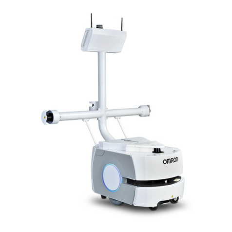
Omron LD-105CT User manual

I612-E-03
LD Cart Transporter
User’s Guide

Copyright Notice
The information contained herein is the property of Omron Adept Technologies, Inc., and shall not be
reproduced in whole or in part without prior written approval of Omron Adept Technologies, Inc. The
information herein is subject to change without notice and should not be construed as a commitment by
Omron Adept Technologies, Inc. The documentation is periodically reviewed and revised.
Omron Adept Technologies, Inc., assumes no responsibility for any errors or omissions in the doc-
umentation. Critical evaluation of the documentation by the user is welcomed. Your comments assist us
in preparation of future documentation. Please submit your
comments to: techpubs@adept.com.
Copyright 2016, 2017 by Omron Adept Technologies, Inc. All rights reserved.
Any trademarks from other companies used in this publication are the property of those respective com-
panies.
MPEG Layer-3 audio coding technology licensed from Fraunhofer IIS and Thomson.
Copyright 2012 CEPSTRAL LLC http://www.cepstral.com This product may contain copyright material
licensed from CEPSTRAL LLC, all right reserved.
This manual was originally written in English.
Created in the United States of America

Table of Contents
Chapter 1: Introduction 11
Definitions 11
1.1 Product Description 11
LD Platform Cart Transporter 13
Cart 16
Coupling 16
Optional Components 16
User-Supplied Components / System Requirements 17
1.2 Software Overview 17
Mobile Robot Software Suite 17
SetNetGo 19
1.3 How Can I Get Help? 19
Related Manuals 19
Support 19
Including a DebugInfo File 20
Chapter 2: Safety 23
2.1 Dangers, Warnings, Cautions, and Precautions 23
2.2 What to Do in an Emergency /Abnormal Situation 23
Releasing the Brakes 23
Releasing an E-Stop 24
2.3 User's Responsibilities 24
General Hazards 24
Falling Hazards 25
Electrical Hazards 25
Pinch Hazards 26
Magnetic Field Hazards 27
Qualification of Personnel 27
Payload Movement and Transfer 28
Configurable Warning Buzzer 28
Multi-AIV Avoidance 29
Traffic Control 29
Passing Lanes 29
2.4 Environment 29
General Environmental Conditions 29
Public Access 29
Clearance 29
Obstacles 30
Safety Scanning Laser Emergency Stop 30
2.5 Intended Use 30
Non-Intended Use 31

Table of Contents
Platform Modifications 31
2.6 Battery Safety 31
2.7 Additional Safety Information 32
Accidental Cart Separation 32
Mobile Robot LDSafety Guide 32
Chapter 3: Setup 33
Overview 33
Tasks 33
3.1 Transport and Storage 34
LD Platform Cart Transporter 34
Battery 34
Standalone Cart 35
3.2 Before Unpacking 35
3.3 Unpacking 35
Battery 36
LD Platform Cart Transporter 37
Repacking for Relocation 40
3.4 Setting Up an LD Platform Cart Transporter 40
Rolling the LD Platform Cart Transporter off of the Crate Base 40
Installing the Battery 43
Installing the Docking Station 47
3.5 Installing the Cart Brake Release 52
Installation 53
Adjustment 56
Chapter 4: Configuration 59
4.1 Settings and Configuration 59
Maintenance Ethernet Connection 59
Setting Up Wireless Ethernet 60
4.2 Mapping 62
Setting Up Cart-Parking Goals 63
Marking Cart-Parking Goals on Floor 63
4.3 Configuring a Touchscreen 63
Touchscreen Ethernet Setup 63
Operating Modes 64
Localization Goals 66
Screen Logo 67
Screensaver 68
Display Language 69
Contact Information 70
4.4 Acceleration, Deceleration, and Rotation Limits 70
4.5 Supplemental Information 71
Laser Setup 71

Table of Contents
Chapter 5: Payloads 73
5.1 Safety 73
Drive Warning Light 73
Turn Warning Lights 73
5.2 Considerations 73
Dimensions 73
Pinch Hazard 73
Weight 74
Center of Gravity 74
5.3 Payload-Related Tradeoffs 79
Chapter 6: Connectivity 81
6.1 Required Connections 81
6.2 LD Platform Cart Transporter Connections 81
Core 81
Cart-Specific PCA 82
6.3 Standard Platform Connections 86
LD Platform Core Front, Upper 87
LD Platform Core Rear, Upper 94
Internal LD Platform Core Connections 101
Core Internal Data Pinouts 102
LD Platform Core Internal Power Pinouts 104
Chapter 7: Operator Interface 107
7.1 Touchscreen 107
Touchscreen Initialization 107
Touchscreen Configuration 108
Screen Top Bar 108
Left Screen Pane 108
Right Screen Pane 110
Center Pane 114
Relocalization 114
Choose Dropoff Mode 114
Patrol Route Mode 117
7.2 Operator Panel 118
E-Stop Button 118
ON Button 119
OFF Button 119
Brake-release (BRAKE)Button 119
Keyswitch 119
LATCH Button 119
UNLATCH Button 119
7.3 Other Controls and Indicators 120
Light Discs and Beacon 120
LD Platform Core Indicators 124

Table of Contents
Battery and Docking Station 125
Chapter 8: Operation 127
8.1 Operating Environment 127
Intended Use 127
Clearance 127
Obstacles 127
Environment and Floor 128
Platform Getting Stuck 128
Cart Getting Stuck on Platform 129
8.2 Typical Operation 129
8.3 Power and Charging 130
Battery Indicators and Controls 130
Docking Station 131
Manually Charging the Battery 133
Balancing the Battery 133
8.4 Startup 135
Procedure 135
Joystick 135
8.5 Working with Carts 136
Goals 136
Operation 136
Cart-Locating 136
Cart Brakes 136
Chapter 9: Options 139
Enterprise Manager 1100 139
MobilePlanner Software (licensed) 139
Joystick 139
Spare Battery 139
Spare Carts 139
Call Buttons/Door Boxes 139
Acuity Localization 140
High-Accuracy Positioning System 140
Chapter 10: Maintenance 141
10.1 Safety Aspects While Performing Maintenance 142
Electrical Hazards 142
Pinch Hazard 143
Magnetic Field Hazards 143
10.2 Lifting the Platform Safely 143
Front Lifting Points 143
Rear Lifting Area 144
10.3 Safety Inspection 145
Warning Devices 145

Table of Contents
Warning Labels 145
Informative Labels 148
10.4 Cleaning 149
Work Area Maintenance 149
LD Platform Cart Transporter and Cart 149
Tires 150
Casters 150
Axles 150
Lasers 150
Docking Station Contacts 150
10.5 Accessing the Payload Bay 150
Removing Latching Mechanism Cover 151
Removing Top Plate 151
Installing Top Plate 151
Installing Latching Mechanism Cover 152
10.6 Removing and Installing LD Platform Cart Transporter Covers 152
Removing Covers 152
Installing Covers 155
10.7 Replacing Periodic Parts 157
10.8 Replacing Non-Periodic Parts 159
Docking Station Roller and Bearing 159
Safety Scanning Laser 160
Obstacle Detection and Coupling Lasers 160
Rear Sonar Units 164
Sonar Controller 164
Cart Latching Mechanism 165
Light Discs 167
Wheels and Tires 167
Drive Assemblies 168
Platform Casters 169
LD Platform Cart Transporter Casters 171
Cart Brake Release 174
LD Platform Core 175
E-Stop and Safety Laser Commissioning 177
Chapter 11: Technical Specifications 179
11.1 Dimension Drawings 179
11.2 Specifications 180
LD Platform Cart Transporter Physical 180
LD Platform Cart Transporter Performance 181
Battery Output 182
Cart 183
Docking Station 183


Revision History
Revision
code Date Revised Content
01 April, 2017 Original release
02 March,
2017
Added 2-second delay after E-Stop recovery; dimensions updated;
MaxVelxxx parameters updated; removed procedure for user replace-
ment of wheels and tires; changed pacemaker/magnet warning to
say medical implant; changed gap and step specs; added instructions
for unlatching a cart that is stuck to a transporter; clarified that max
payload does NOT include the cart itself; use of joystick warning mod-
ified.
03 September,
2017
Update product name, battery specifications, and image of joystick.
Added instructions for updated shipping crate. Regulatory changes,
specification changes, and E-stop instruction clarifications.
04 November,
2017
Clarify that the material on the Latching Mechanism is acetal.
Removed sentence with example regarding safety laser com-
missioning speed zones.
14766-000 Rev E LD Platform Cart Transporter User's Guide 9


Chapter 1: Introduction
This manual covers the setup, operation, and user maintenance of an LD Platform Cart Trans-
porter and cart.
The basic configuration performed using the software that comes with the system is covered.
Full details of that configuration are covered in the Mobile Robot Software Suite User's Guide.
Definitions
Platform: The most basic part of the robot. It includes the chassis, drive assemblies, sus-
pension, wheels, battery, safety scanning laser, obstacle-avoidance lasers, sonar, an on-board
LD Platform core with built-in gyroscope, software needed to navigate, connectors for inter-
facing with and powering the Operator panel and cart coupling system, Operator panel, and
the platform covers.
LD Platform Cart Transporter:A platform with the LDPlatform OEM (including extended
arms)and the coupling plate attached, set up to transport a cart. This is also referred to as just
a transporter.
Cart:A cart, on four casters, that can be attached to an LD Platform Cart Transporter, for
increasing the payload capacity. The cart has brakes on two casters, which can be released
either by coupling with a transporter, or by using a manual brake-release lever on the cart.
AIV (Autonomous Intelligent Vehicle):The LD Platform Cart Transporter with a cart attached
to it. This is the complete mobile robot, which will transport your payload on the cart.
For the initial setup, configuration, and connections, we will refer to the platform.
For controlling or monitoring the full mobile robot, with a cart attached, we will refer to the
AIV.
1.1 Product Description
The LD Platform Cart Transporter is a general-purpose mobile platform designed for moving a
detachable cart indoors and around people. It is self-guided and self-charging, with an auto-
mated docking station.
The platform, which moves the cart, comes complete with the ability to know where it is
within your workspace, and to navigate safely and autonomously to any accessible destination
within that workspace, continuously and without human intervention.
The LD Platform Cart Transporter is intended to expand the range of payloads that can be
moved by a platform, both in weight and size.
The LD Platform Cart Transporter is available in two models, designed to transport carts with
a payload up to 105 kg (231 lb)for the LD-105CT and 130 kg (287 lb) for the LD-130CT plat-
form. Where appropriate, differences between the models are called out. Otherwise, this
manual applies to both LD Platform Cart Transporters.
14766-000 Rev E LD Platform Cart Transporter User's Guide 11

12 LD Platform Cart Transporter User's Guide 14766-000 Rev E
1.1 Product Description
Figure 1-1. Cart and LD Platform Cart Transporter, Separate
Figure 1-2. Cart and LD Platform Cart Transporter, Coupled

Chapter 1: Introduction
LD-130CT
LD-105CT
Figure 1-3. LD Platform Cart Transporter Model Labels
LD Platform Cart Transporter
The LD Platform Cart Transporter is a mobile platform, designed for working around people
while moving a cart. It is self-guided and self-charging, with an automated docking station.
The transporter combines hardware and mobile-robotics software to provide an intelligent,
mobile platform to transport your payload on the cart. Its primary guidance uses a safety scan-
ning laser to navigate, comparing the laser readings to a digital map stored on the platform.
The laser is backed up by a gyroscope mounted on the internal core, and encoders and Hall
sensors on each drive wheel.
In addition to the front safety scanning laser, each LD Platform Cart Transporter has two side
lasers, for detecting potential obstacles in its path, a low front laser in the bumper to detect
obstacles lower than the safety scanning laser, and a rear-facing obstacle-detection laser, to
ensure that it is safe for the transporter to back up or turn in place.
For situations that are so dynamic that laser localization becomes difficult, we offer the Acuity
Localization option, which localizes the AIV using an upward-facing camera to recognize over-
head lighting patterns. This would apply to areas where objects, such as pallets or carts, are
moved so frequently that they can’t be mapped, or where they block the laser’s view of fea-
tures that are mapped. This is covered in the LDPlatform Peripherals Guide.
Body and Drive
The LD Platform Cart Transporter is relatively small, lightweight, and highly maneuverable. It
has a strong aluminum chassis and solid construction that makes it very durable.
The platform is a two-wheel, differential-drive vehicle, with spring-loaded passive casters front
and rear for balance. The drive-wheels have independent spring-suspension, with solid, foam-
filled tires. The wheels are at the mid-line of the platform, so that the platform can turn in
place.
Safety Scanning Laser
The onboard safety scanning laser is a very precise scanning sensor. The laser provides 500
readings in a 240 degree field of view, with a typical maximum range of 15 m (49.2 ft). The
14766-000 Rev E LD Platform Cart Transporter User's Guide 13

14 LD Platform Cart Transporter User's Guide 14766-000 Rev E
1.1 Product Description
laser operates in a single plane, positioned at 201 mm (7.9 inches) above the floor. In most
environments, the sensor will provide highly-accurate data.
Glass, mirrors, and other highly-reflective objects cannot be reliably detected by the laser. Cau-
tion must be exercised when operating the AIV in areas that have these types of objects. If the
AIV will need to drive in close proximity of these objects, we recommend that you use a com-
bination of markings on the objects, such as tape or painted strips, and also use forbidden sec-
tors in the map, so that the AIV knows to plan paths safely around these objects.
Side Lasers
These two lasers are used to detect obstacles that protrude into the AIV's path, but may not be
detected by the safety scanning laser.
This is needed when obstacles higher than the safety scanning laser (but low enough to be
obstacles)protrude into the AIV‘s path.
Low Front Laser
This laser is mounted to the front bumper. It detects obstacles that are low and in front of the
transporter, such as an empty pallet, which might be too low for the safety scanning laser to
see.
Rear-Facing Laser
This laser gives better coverage of what’s behind the transporter than sonar alone. It is used
during both turning in place and backing up when the transporter and cart are coupled.
Coupling Laser
A laser mounted in the transporter coupling plate is used to locate a triangle on the underside
of the cart’s coupling plate. This is used by the transporter to accurately align with the cart, so
it can couple with it.
Sonar
The LD Platform Cart Transporter’s two rear-facing sonar pairs are for obstacle-sensing while
backing up. The range is up to 5 m (16 ft), though the typical accurate range is only up to 2 m
(10 ft). Each pair consists of one emitter and one receiver. The sonar emitters and receivers are
identical physically, but the transporter uses them differently.
Encoders and Gyroscope
Each wheel has an encoder that tells the navigation system how far the wheel has turned, and
in which direction. Each wheel also has a Hall sensor.
The LD Platform core has a gyroscope mounted on it, to track the AIV's rotation.
The combination of rotation and distance traveled are used by the platform to back up the
safety scanning laser during localization. These limit the area on the platform's map that the
AIV needs to search when localizing.

Chapter 1: Introduction
What’s Included with an LD Platform Cart Transporter
lOne fully-assembled platform
The platform includes a safety scanning laser, a low front laser, two side lasers, a rear-
facing laser, and two rear-facing sonar pairs. Each pair is one transmitter and one
receiver.
lOne battery
This is shipped separately from the platform, due to air shipping regulations.
If the battery was shipped by air, it will be at less than 30% charge per IATA reg-
ulations.
lTop plate and coupling plate
The platform top plate covers the payload bay of the platform, and supports the lower
(platform)coupling plate, which engages the cart coupling plate, attached to the cart,
and the coupling laser.
lLD Platform core, which includes an integrated computer, running Advanced Robotics
Automation Management (ARAM) and a microcontroller with MARC firmware. The
core is housed inside the platform. It also runs the SetNetGo OS.
ARAM and MARC firmware and the SetNetGo OS are pre-loaded on the LD Platform
Core.
lAn HMIPost
This supports the two side lasers and the rear-facing laser, both for obstacle avoidance.
It also supports the Operator Panel.
lOperator Panel
This includes a touchscreen, an E-Stop button, ON and OFF buttons, a brake-release but-
ton, and a keyswitch, which can be locked, and key removed, in either position. The
panel’s frame supports two WiFi antennas and a beacon.
There are LATCH and UNLATCH buttons below the E-Stop.
The optional Acuity Localization camera mounts on top of the Operator panel frame, on
the same plane as the antennas and beacon.
lAutomated docking station
This allows the LD Platform to charge itself, without user intervention. It includes a
wall-mount bracket and a floor plate, for a choice of installation methods. See Installing
the Docking Station on page 47.
A manual charging cord is included, so you can charge a spare battery outside of the
platform.
lJoystick (option)
This is used for manually controlling the AIV, mostly when making a scan to be used
for generating a map.
At least one joystick is needed for each fleet of AIVs. Once a map is generated, the map
can be shared with multiple AIVs working in the same space.
14766-000 Rev E LD Platform Cart Transporter User's Guide 15

16 LD Platform Cart Transporter User's Guide 14766-000 Rev E
1.1 Product Description
Cart
The cart is a frame mounted on four casters, designed so that it can couple with an LD Plat-
form Cart Transporter. Once coupled, the cart moves with the transporter. When the trans-
porter arrives at the intended goal, it uncouples from the cart and leaves, while the cart
remains at the goal. Brakes automatically engage on the cart casters, preventing it from rolling
in case the floor isn’t completely level.
The cart has a manual brake-release lever, so it can be moved manually.
Coupling
The LD Platform Cart Transporter can attach to a cart at a pickup goal, move the cart to a
dropoff goal, and leave it at that goal, with no human intervention.
When the cart and transporter are coupled, the transporter automatically presses a lever that
releases the cart’s brakes, so it is free to move with the transporter.
The coupling system has:
la motorized Latching Mechanism
la coupling laser
This is mounted in the coupling plate, and is used to align the transporter with the cart
when coupling.
lLATCH and UNLATCH override buttons, on the Operator Panel
Coupling Plates
Each cart has one coupling plate, and each platform has one coupling plate. The plates are
mounted so that, when the platform moves under the cart, the plates can attach to each other,
allowing the platform to move the cart. The software is aware of whether or not a cart is
attached.
lThe cart coupling plate includes a slot that can be latched with the platform coupling
plate. The cart coupling plate is passive.
lThe platform coupling plate includes a laser, for aligning the platform before coupling,
and a motorized Latching Mechanism, for latching the cart coupling plate.
Optional Components
Refer to Options on page 139 for details.
lAcuity Navigation
For environments that are very dynamic, such that a map can’t be kept current, or
where the area is too large for the navigation laser to see, Acuity can be used to nav-
igate using overhead light patterns seen with an upward-facing camera.
lEnterprise Manager 1100
This system manages a fleet of AIVs, for multi-AIV traffic coordination and job man-
agement. It includes the Enterprise Manager appliance running the Mobile Software
suite.

Chapter 1: Introduction
lSpare battery
A spare battery can be used to minimize down-time. Swapping the battery for a fully-
charged battery avoids taking the AIV out of service for more than a few minutes.
lCall/Door Boxes
These allow an AIV to be requested from a remote location, or allow the AIV system to
control an automated door, so the AIV can pass through it.
User-Supplied Components / System Requirements
PC with Microsoft Windows®
lEthernet (wireless preferred)
Wireless is required for a fleet (more than one AIV).
l100 megabytes of available hard-disk storage
1.2 Software Overview
Mobile Robot Software Suite
The Mobile Robot Software Suite includes all of the software used for platforms and the Enter-
prise Manager appliance, with the exception of the SetNetGo OS.
ARAM
The Advanced Robotics Automation Management software (ARAM) runs on the LD Platform
core. It operates ranging sensors like the safety scanning laser and sonar, and performs all the
high-level, autonomous robotics functions, including obstacle avoidance, path planning, loc-
alization, navigation, and so on, culminating in motion commands to the MARC firmware.
ARAM also controls the battery and light discs, and manages digital and analog I/O, which,
along with platform power, provide for integration of application-specific sensors and effectors
that the user adds.
ARAM manages wired and wireless Ethernet communications with offboard software, for
external monitoring, development, and systems coordination, including coordination of a fleet
of AIVs through the optional Enterprise Manager 1100. It also manages integration with other
systems, as well as external monitoring, setup, and control with the MobilePlanner applic-
ation.
ARAMCentral
ARAMCentral is the software that runs on the Enterprise Manager appliance. This software
and the appliance combined are referred to as the Enterprise Manager 1100.
For a fleet, the ARAMCentral software manages:
lthe map that all AIVs use
lthe configuration that all AIVs use
ltraffic control of the AIVs
This includes multi-AIV avoidance, destination, standby, and dock control.
14766-000 Rev E LD Platform Cart Transporter User's Guide 17

18 LD Platform Cart Transporter User's Guide 14766-000 Rev E
1.2 Software Overview
lqueuing of jobs for the AIVs
lremote I/O, if you are using it
MobilePlanner (licensed)
In order to have your AIV perform autonomous mobile activities, you need to make a map of
its operating space, and configure its operating parameters. The MobilePlanner software is
used to make this map and perform this configuration.
Refer to the separate Mobile Robot Software Suite User's Guide for details on how to map a work-
ing space and prepare the virtual elements, goals, routes, and tasks for your application. In par-
ticular, refer to:
Working With Map Files > Editing a Map File > Using the Drawing Tools >
Adding Goals and Docks
The MobilePlanner software requires a license to run. You will need at least one license for
MobilePlanner for each fleet of AIVs. Once you generate a map for an area, it can be shared
between multiple AIVs in one fleet.
MobilePlanner, Operator Mode
The MobilePlanner Operator Mode is used to monitor one or more AIV's activities and have
them perform mobile tasks in the mapped space. When MobilePlanner is started without its
license dongle, it automatically starts in this mode. Refer to the separate Mobile Robot Software
Suite User's Guide for details.
Mobile Adept Robot Controller (MARC)
At the lowest level, a microcontroller running MARC firmware handles the details of platform
mobility, including maintaining the platform’s drive speed and heading, as well as acquiring
sensor readings, such as from the encoders and gyroscope, and managing the platform’s emer-
gency stop systems, bumper, and joystick. The MARC firmware computes and reports the plat-
form’s odometry (X, Y, and heading) and a variety of other low-level operating conditions to
ARAM.
Touchscreen Support
Whenever the Mobile Software suite is downloaded, it includes support software for the
optional touchscreen.
Call/Door Box Support
Call/Door boxes have one software component on the box and another on either the Enterprise
Manager 1100 or on the single AIV, when there is no Enterprise Manager 1100.
ARCL Protocol
ARCL is a function of ARAM and ARAMCentral, which is included as part of this suite.
The Advanced Robotics Command Language, or ARCL, is a simple text-based command and
response server for integrating an AIV (or fleet of AIVs) with an external automation system.
ARCL allows you to operate and monitor the AIV, its accessories, and its payload devices over
the network, with or without MobilePlanner.

Chapter 1: Introduction
SetNetGo
The SetNetGo OS runs on the LD Platform core and Enterprise Manager appliance. It is the
host OS in which ARAM and ARAMCentral run.
The SetNetGo interface in the MobilePlanner software is used for configuring the Ethernet set-
tings for the platform, upgrading software, and performing systems diagnostics, such as
retrieving log files. It can be accessed when connected via the maintenance and management
Ethernet ports, or via wireless Ethernet if enabled.
NOTE:It is possible to connect directly to the SetNetGo OSon a platform through a
web browser. The main intent of this is to allow your IT support to set up the net-
work for you, without using MobilePlanner, which requires a license.
1.3 How Can I Get Help?
Refer to the corporate websites:
http://www.ia.omron.com
and
http://www.adept.com
Related Manuals
This manual covers the installation, setup, operation, and maintenance of an LD Platform Cart
Transporter. There are additional manuals that cover these actions for the platform.
Table 1-1. Related Manuals
Manual Title Description
Mobile Robot LDSafety
Guide
Contains general safety information for all of our LD Platforms.
Mobile Robot Software
Suite User's Guide
Covers MobilePlanner software, the SetNetGo OS, and most of
the configuration of an LD Platform.
Enterprise Manager
1100 User's Guide
Covers the Enterprise Manager 1100 system, which is hardware
and software used for managing a fleet of AIVs.
LDPlatform Peripherals
Guide
Covers peripherals, such as the Touchscreen, Call/Door box, and
Acuity Localization options.
Support
If, after reading this manual, you are having problems with your LD Platform Cart Trans-
porter, contact your local Omron support.
lIn the body of your e-mail message, provide your platform’s serial number and describe
the problem you are having in as much detail as possible.
lAttach your debuginfo file to the email. Refer to the next section for details on retrieving
your debuginfo file. See the following section for generating your debuginfo file.
14766-000 Rev E LD Platform Cart Transporter User's Guide 19

20 LD Platform Cart Transporter User's Guide 14766-000 Rev E
1.3 How Can I Get Help?
Including a DebugInfo File
If the platform has been set up on a wireless network, skip to SetNetGo Access on page 20.
Network Setup
If the AIV has not been set up on a wireless network, a local area network will have to be set
up on a separate PC, and configured to talk to the AIV over a TCP/IP port. The IP address
should be set to: 1.2.3.5. The Subnet Mask should be 255.255.255.0.
(Windows 7)Start >Control Panel >(Network and Internet >)Network and Sharing Center
>Change adapter settings
Right-click on the LAN Connection, and click on Properties.
From the Properties dialog, scroll to and double-click the Internet Protocol (TCP/IP or
TCP/IPv4) option. In Internet Protocol Properties, click both “Use the following…” radio but-
tons to enable them, and then type in the IP and netmask values.
Connect the network port of your computer to the platform's Maintenance port. See the figure
Location of Parts in the Payload Bay on page 142.
SetNetGo Access
If the MobilePlanner software is available, use the SetNetGo interface within that software to
access SetNetGo. Otherwise, open a web browser and enter the URL: https://1.2.3.4:
You will be requested to confirm security certificates.
Other manuals for LD-105CT
1
This manual suits for next models
1
Table of contents
Other Omron Farm Equipment manuals