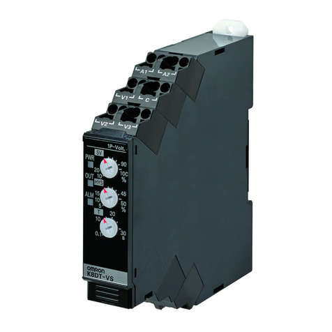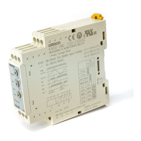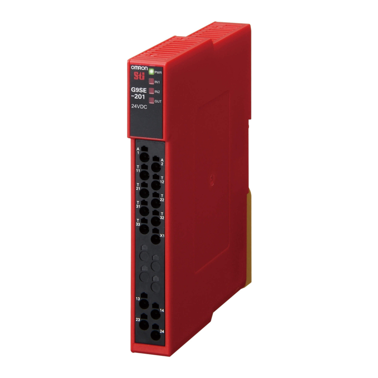
RELAYTERMINAL
0631610-1 B
ThankyouforpurchasinganOMRONproduct.
Confirmproductwhichmustberequiredandreadthismanual
throughlyforcorrectusebeforeactuallyusingit.
Keepthismanualforreference.
Thismanualdescribesonlythemainprecautionstobeobserved.
■ Accessories(SoldSeparately)
●Donotsubmittheproducttoabnormalshock.Doingsomightresultinfaultyoperation.
●UsetheUnitwiththecorrectpowersupplyvoltage.Anincorrectpowersupplymayresultinaproblem.
●Double-checkallthewiringbeforeturningonthepowersupply.
Incorrectwiringmayresultinburning.
●Donotbendthecablesbeyondtheirnaturallimit.Doingsomaybreakthecables.
●Donotpullthecablesbythepowerbeyond30N.Doingsomaybreakthecables.
●Besuretoturnoffthepowersupplybeforewiring.Oncethepoweristurnedon,keepthecover
closedanddonottouchtheterminalblock,otherwiseanelectricalshockaccidentmayoccur.
●EnsureDINrailattachmentorscrewattachment.
●Neverusetheproductunderanyloadthatexceedstheratedcontactvaluesincludingtheswitching
capacities,otherwisetheproductwillnotoperatecorrectlyanddamageorburningmayoccurwith
theproductitself.
●Takeappropriatemeasurestoensurethatthespecifiedpowerwiththeratedvoltageandfrequencyis
supplied.Beparticularlycarefulinplaceswherethepowersupplyisunstable.Anincorrectpower
supplymayresultinmalfunction.
●Donotattempttodisassemble,repair,ormodifyanyUnits.Anyattempttodosomayresultin
malfunction,fire,orelectricshock.
●Applyspecifiedvoltagecorrectlytotheinputterminal.Applicationofwrongvoltagewillspoilthe
specifiedperformanceofthisproductandmaybreakorburntheproductitself.
●DonotinstalltheUnitinanyofthefollowinglocations.InstallingtheUnitinthefollowinglocationsmay
resultinmalfunction,electricshock,orburning.
・Locationssubjecttocondensationastheresultofseverechangesintemperature.
・Locationssubjecttocorrosiveorflammablegases.
・Locationssubjecttoexposuretowater,oil,orchemicals.
・Locationssubjecttodirectsunlight.
・Locationssubjecttodust(especiallyirondust)orsalts.
・Locationssubjecttoshockorvibration.
・Locationssubjecttotemperaturesorhumiditiesoutsidetherangespecifiedinthespecifications
●Takeappropriateandsufficientcountermeasureswheninstallingsystemsinthefollowinglocations.
Inappropriateandinsufficientmeasuresmayresultinmalfunction.
・Locationsclosetopowersupplies.
・Locationssubjecttostaticelectricityorotherformsofnoise.
・Locationssubjecttostrongelectromagneticfields.
●WhenmountingaRelay,presstheupperpartoftheRelaystraightdownuntiltheRelayislockedwith
thehookswhilemakingsurethatnoneoftheRelayterminalsarebent.
NotdoingsomaycausetheI/OTerminaltomalfunctionorradiateheat.
●Never use paint thinner or similar solvents, which can discolor or dissolve the sunface of the Unit.
●AvoidconnectinganddisconnectingconnectorswhilethepowerisON.Otherwise,misoperationmay
occur.
G70D(R)-SOC08
●G70R-SOC08
■ TerminalArrangement/ConnectingExternal
●G70D-SOC08 ●G70R-SOC08
■ Dimensions(Unit:mm)
●G70D-SOC08 ●G70R-SOC08
・BesuretomountusingM4screwsormountata35mmDINrailusingtheDINrailattachmenthook.
Donotinstalltheproductinplacestobetouchedbyaccidenttoavoidmalfunctioncausedbystatick
electricity.
・Sincethevoltagetobeappliedisspecified,supplythepowerthatmeetsthevoltagespecificationtothe
terminals(24V,0V)whenusingtherelayterminal.Theterminals(A0〜7,B0〜7)arecontactoutputs.
Thereforesupplythepowerthatmeetstheload.Short-circuitboardsarealsoavailable.
・Thepowertake-interminalsservetosupplytherelaydrivepowerandthecontrolleroutputtransistor
power.Matchthecontrollervoltagewiththerelayterminalvoltage.Usethepowersupplyhavingleast
noise.
■InternalCircuit
●G70D-SOC08
Connectorisof20-pintypeand
11〜18areopen.
RY100…(1)20
RY101…(2)18
RY102…(3)16
RY104…(4)14
RY105…(5)12
RY106…(6)10
RY107…(7)8
RY108…(8)6
0V…(9)4
24V…(10)2
19(11)
17(12)
15(13)
13(14)
11(15)
9(16)
7(17)
5(18)
3(19)…0V
1(20)…24V
▲mark
ArrengementofConnectorPins
(TOPVIEW)
Connectorisof20-pintypeand
11〜18areopen.
RY100…(1)20
RY101…(2)18
RY102…(3)16
RY103…(4)14
RY104…(5)12
RY105…(6)10
RY106…(7)8
RY107…(8)6
0V…(9)4
24V…(10)2
19(11)
17(12)
15(13)
13(14)
11(15)
9(16)
7(17)
5(18)
3(19)…0V
1(20)…24V
▲mark
ArrengementofConnectorPins
(TOPVIEW)
Applicablemodel
G70D-SOC08
G70R-SOC08
Coilratedvoltage
24VDC
24VDC
Model
G6D-1A-ASI
G2R-1-S(N)
Applicablemodel
G70D-SOC08
G70R-SOC08
model
G6B-4-SB
●ReplacementRelays
●ConnectorCable
●ShortBar
24V 0V
B0 B1 B2 B3
A0 A1 A2 A3
24VDC
Load
Load
Load
Load
Load
Load
Load
Load
〜
B4 B5 B6 B7
A4 A5 A6 A7
24V 0V
B0 B1 B2 B3 B4 B5 B6 B7
A0 A1 A2 A3 A4 A5 A6 A7
24VDC
Load
Load
Load
Load
Load
Load
Load
Load
〜
LED101 LED102 LED103 LED104 LED105 LED106 LED107
LED100
RY100
20
18
16
14
12
10
8
6
RY101 RY102 RY103 RY104 RY105 RY106 RY107
1
2
3
4
C1
D1
24V
0V
B0
A0
B1
A1
B2
A2
B3
A3
B4
A4
B5
A5
B6
A6
B7
A7
RY100
20
18
16
14
12
10
8
6
1
2
3
4
C1
D1
24V
0V
B0
A0
B1
A1
B2
A2
B3
A3
B4
A4
B5
A5
B6
A6
B7
A7
RY101 RY102 RY103 RY104 RY105 RY106 RY107
136.2
68.2
54.6
92.8
43.5
92.8
7.1
7.1
76543210
Whentheproductisusedunderthecircumstancesorenvironmentbelow,ensureadherence
tolimitationsoftheratingsandfunctions.Also,takecountermeasuresforsafetyprecations
suchasfail-safeinstallations.
1.Useundercircumstancesorenvrionmentwhicharenotdescribedindescribedinstructionmanual.
2.Usefornuclearpowercontrol,railway,aircraft,vehicle,incinerator,medical
equipment,entertainmentequipment,safetydeviceetc.
3.Useforapplicationswheredeathorseriouspropertydamegesispossibleand
extensivesafetyprecautionsarerequired.
Errorrate(levelP,referencevalue)
5VDC1mA
5VDC100mA
PrintedinJapan
・CablewithLooseWireandCrimpTerminals:XW2Z-RY□C
・CablewithLooseWires:XW2Z-RA□C
・Cablewithconnectors
‒Fujitsuconnectors(1:1):XW2Z-R□C
Fujitsuconnectors(1:2):XW2Z-RI□C-□,XW2Z-RO□C-□
Fujitsuconnectors(1:3):XW2Z-R□C-□-□
‒MILconnectors(1:1):XW2Z-RI□C,XW2Z-RO□C
‒MILconnectors(1:2):XW2Z-RI□-□-D□,XW2Z-RM□-□-D□,XW2Z-RO□-□-D1
* Checktheinternalcircuitbeforeuseandconfirmthepinstobeused.
RefertotheXW2Z-RDatesheet(Cat.No.G126)fordetails.
