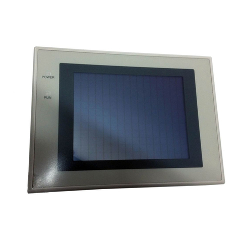
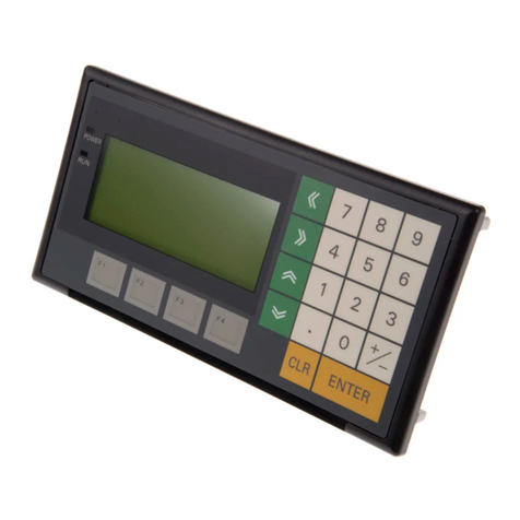
Omron NT30C-ST141-E User manual

-~
ARTISAN
®
~I
TECHNOLOGY
GROUP
Your definitive source
for
quality
pre-owned
equipment.
Artisan Technology
Group
Full-service,
independent
repair
center
with
experienced
engineers
and
technicians
on staff.
We
buy
your
excess,
underutilized,
and
idle
equipment
along
with
credit
for
buybacks
and
trade-ins
.
Custom
engineering
so
your
equipment
works
exactly as
you
specify.
•
Critical
and
expedited
services
•
Leasing
/
Rentals/
Demos
• In
stock/
Ready-to-ship
•
!TAR-certified
secure
asset
solutions
Expert
team
ITrust
guarantee
I
100%
satisfaction
All
tr
ademarks,
br
a
nd
names, a
nd
br
a
nd
s a
pp
earing here
in
are
th
e property of
th
e
ir
r
es
pecti
ve
ow
ner
s.
Find the OMRON NT30C-ST141-E at our website: Click HERE

Cat. No. V034-E1-5
Programmable Terminal
NT30/30C

NT30/30C Programmable Terminal
Operation Manual
Revised January 2001

iv

!
!
!
v
Notice:
OMRON products are manufactured for use according to proper procedures by a qualified operator
and only for the purposes described in this manual.
The following conventions are used to indicate and classify precautions in this manual. Always heed
the information provided with them. Failure to heed precautions can result in injury to people or dam-
age to property.
DANGER Indicates an imminently hazardous situation which, if not avoided, will result in death or
serious injury.
WARNING Indicates a potentially hazardous situation which, if not avoided, could result in death or
serious injury.
Caution Indicates a potentially hazardous situation which, if not avoided, may result in minor or
moderate injury, or property damage.
OMRON Product References
All OMRON products are capitalized in this manual. The word “Unit” is also capitalized when it refers
to an OMRON product, regardless of whether or not it appears in the proper name of the product.
The abbreviation “Ch,” which appears in some displays and on some OMRON products, often means
“word” and is abbreviated “Wd” in documentation in this sense.
The abbreviation “PC” means Programmable Controller and is not used as an abbreviation for any-
thing else.
The abbreviation “host” means a controller, such as an FA computer, that controls a PT (Program-
mable Terminal).
Visual Aids
The following headings appear in the left column of the manual to help you locate different types of
information.
Note Indicates information of particular interest for efficient and convenient operation
of the product.
Reference Indicates supplementary information on related topics that may be of interest to
the user.
1, 2, 3... 1. Indicates lists of one sort or another, such as procedures, checklists, etc.
OMRON, 1995
All rights reserved. No part of this publication may be reproduced, stored in a retrieval system, or transmitted, in any
form, or by any means, mechanical, electronic, photocopying, recording, or otherwise, without the prior written permis-
sion of OMRON.
No patent liability is assumed with respect to the use of the information contained herein. Moreover, because OMRON is
constantly striving to improve its high-quality products, the information contained in this manual is subject to change
without notice. Every precaution has been taken in the preparation of this manual. Nevertheless, OMRON assumes no
responsibility for errors or omissions. Neither is any liability assumed for damages resulting from the use of the informa-
tion contained in this publication.

vi

TABLE OF CONTENTS
vii
PRECAUTIONS xi.................................
1 Intended Audience xii...........................................................
2 General Precautions xii..........................................................
3 Safety Precautions xiii...........................................................
SECTION 1
Functions of the NT30/30C 1........................
1-1 Role and Operation of NT30/30C 2...........................................
1-2 Functions of NT30/30C 4...................................................
1-3 System Configuration 7.....................................................
1-4 Communications Using the Direct Connection Function 8.........................
1-5 Before Operating 13........................................................
SECTION 2
Hardware Settings and Connections 15................
2-1 Description of Parts and Settings 16............................................
2-2 Installation 19.............................................................
2-3 Connecting to the Support Tool 21.............................................
2-4 Installing the System Program 22..............................................
2-5 Connection to a PC by Host Link via RS-232C 23................................
2-6 Connection to a PC by Host Link via RS-422A 40................................
2-7 Connection to a PC by the NT Link 56.........................................
2-8 Connecting a Printer 63......................................................
2-9 Connection of Expanded I/O 64...............................................
SECTION 3
System Menu Operation 73..........................
3-1 Operation Flow by the System Menu 74........................................
3-2 Starting the NT30/30C 74....................................................
3-3 Operation Modes and the System Menu 75......................................
3-4 Initializing Memory 78......................................................
3-5 Setting Communications with the PC Using Memory Switches 83....................
3-6 Registering the Screen Data 89................................................
3-7 Starting the Operation 91....................................................
3-8 System Settings 92.........................................................
3-9 System Maintenance 100.....................................................
SECTION 4
NT30/30C Functions 115.............................
4-1 Creating and Transmitting Screen Data 116.......................................
4-2 Outline of Functions 123......................................................
4-3 Screen Displays 131.........................................................
4-4 Memory Tables 136..........................................................
4-5 Graphs 141.................................................................
4-6 Lamps 151.................................................................
4-7 Touch Switches 154..........................................................
4-8 Numeral Setting 161.........................................................
4-9 Character String Setting 171...................................................
4-10 Pop-Up Window Function 173.................................................
4-11 Alarm List & History Display Functions 180......................................
4-12 Operation of B7A Units 185...................................................
TABLE OF CONTENTS
viii
SECTION 5
Using Host Link and NT Link 189......................
5-1 Outline of Host Link and NT Link Operations 190.................................
5-2 Memory Tables and Graphs 201................................................
5-3 Lamps and Touch Switches 216................................................
5-4 Numeral and Character String Setting 224........................................
5-5 Alarm Lists 229.............................................................
5-6 Clock Function 234..........................................................
5-7 NT30/30C Status Control 239..................................................
5-8 Notifying the PC of PT Operating Status 244.....................................
SECTION 6
Troubleshooting and Maintenance 247..................
6-1 Hardware Faults 248.........................................................
6-2 Responding to Displayed Error Messages 249.....................................
6-3 Maintenance of the NT30/30C 252..............................................
6-4 Inspection and Cleaning 255...................................................
Appendices
A Specifications 257.............................................................
B Dimensions 263...............................................................
C Using RS-232C/RS-422A Link Adapters 265........................................
D NT30/30C Internal Processing 267................................................
E Making the Cable to Connect to the PC 271.........................................
F Connecting Cable Specifications 281..............................................
G Connection Using RS-232C/RS-422A Link Adapters 283..............................
H Standard Models 285...........................................................
I Options 291..................................................................
J PC Memory Maps 293..........................................................
K Special Characters 295.........................................................
Index 297..........................................
Revision History 303.................................

ix
About this Manual:
This manual describes the basic functions and operating procedures of the NT-series NT30/30C Pro-
grammable Terminals and their operation when connected to a PC or other host. It includes the sections
described below.
Please read this manual carefully and be sure you understand the information provided before attempting
to install and operate an NT-series NT30/30C Programmable Terminal.
Section 1 describes the operating functions, system configuration, and the direct connection function of
the NT30/30C.
Section 2 describes the hardware settings, installation to a control panel, connection to optional devices
and connection to a PC.
Section 3 describes the procedure to follow before using the NT30/30C, installation of optional devices,
and convenient functions when using the NT30/30C. Also includes information such as how to check
NT30/30C operation.
Section 4 describes the functions of the NT30/30C when it is connected to a PC.
Section 5 describes how to use the NT30/30C when it is connected to the PC using a Host Link or NT
Link.
Section 6 describes the corrective action to take when the system does not operate normally, and how to
carry out daily maintenance of the NT30/30C.
The Appendices provide information on specifications, dimensions using an RS-232C/RS-422A Link
Adapter, NT30/30C internal processing, making the cable to connect to a PC, connecting cable specifica-
tions, connection using an RS-232C/RS-422A Link Adapter, standard models, options, PC memory
maps, and special characters.
Related Manuals:
Related manuals are listed below. Suffixes have been omitted from the catalog
numbers. Be sure you are using the correct revision of the manual.
Purpose Name Contents Cat. No.
Operating the
Programmable
Terminal and
communicating
with the host
NT30/30C Programmable
Terminal Operation Manual
(this manual)
This is the manual for the NT30/30C itself. This
operation manual describes the functions and
handling of both the Programmable Terminal
and the host interface function.
V034
Creating and
transferring
screen data
NT-series Support Tool
Operation Manuals
The screens displayed on the NT30/30C are
created with the Support Tool and transferred to
the NT30/30C. These manuals describe how to
create and transfer screen data.
V028 and
V061
WARNING Failure to read and understand the information provided in this manual may result in
personal injury or death, damage to the product, or product failure. Please read each
section in its entirety and be sure you understand the information provided in the section
and related sections before attempting any of the procedures or operations given.
!

xi
PRECAUTIONS
This section provides general precautions for using the Programmable Terminal.
The information contained in this section is important for the safe and reliable application of the Programmable Ter-
minal. You must read this section and understand the information contained before attempting to set up or operate a
Programmable Terminal.
1 Intended Audience xii...........................................................
2 General Precautions xii..........................................................
3 Safety Precautions xiii...........................................................

!
!
3General Precautions
xii
1 Intended Audience
This manual is intended for the following personnel, who must also have knowl-
edge of electrical systems (an electrical engineer or the equivalent).
SPersonnel in charge of installing FA systems.
SPersonnel in charge of designing FA systems.
SPersonnel in charge of managing FA systems and facilities.
2 General Precautions
The user must operate the PT according to the performance specifications de-
scribed in the operation manuals.
Before using the PT under conditions that are not described in the manual or ap-
plying the PT to nuclear control systems, railroad systems, aviation systems, ve-
hicles, combustion systems, medical equipment, amusement machines, safety
equipment, and other systems, machines, and equipment that may have a seri-
ous influence on lives and property if used improperly, consult your OMRON rep-
resentative.
Make sure that the ratings and performance characteristics of the PT are suffi-
cient for the systems, machines, and equipment, and be sure to provide the sys-
tems, machines, and equipment with double safety mechanisms.
This manual provides information for using the Programmable Terminal. Be sure
to read this manual before attempting to use the software and keep this manual
close at hand for reference during operation.
SIf a faulty PT is returned for repairs, write as detailed a description of the fault as
possible and send the description together with the PT to the OMRON address
indicated on the back cover of this book.
SWhen disposing of an NT that is no longer required, be sure to comply with all
local restrictions that apply to its disposal.
WARNING It is extremely important that Programmable Terminals and related devices be
used for the specified purpose and under the specified conditions, especially in
applications that can directly or indirectly affect human life. You must consult
with your OMRON representative before applying Programmable Terminals to
the above mentioned applications.
WARNING Do not use input functions such as PT touch switches for applications where
danger to human life or serious damage is possible, or for emergency switch
applications.

!
!
3Safety Precautions
xiii
3 Safety Precautions
Read these safety precautions carefully and make sure you understand them
before using the Programmable Terminal so that you can use it safely and cor-
rectly.
WARNING
SNever attempt repairs, modification or disassembly. You could sustain an elec-
tric shock.
SSwitch OFF the PT power before changing the backlight. You could sustain an
electric shock if you attempt to change the backlight while power is being sup-
plied.
Caution
SWhen disposing of a used backlight, comply with all local restrictions that apply
to its disposal.
SWhen replacing the battery, do not allow the battery terminals to touch the
board in the PT.
SIf not backed up by the built-in battery, the memory switch settings will be initial-
ized to the values set with the NT-series Support Tool when the power is turned
OFF. If a message indicating that the battery is low is displayed while the PT is
being used, replace the built-in battery immediately. For details on how to re-
place the battery, refer to Replacing the Battery (page 253).
SSwitch OFF the power supply to both the PT and the B7A Interface Unit before
installing the B7A Interface Unit, otherwise the PT or the B7A Interface Unit
may be damaged.
SSwitch OFF the power supply to both the PT and the B7A Interface Unit before
changing DIP switch settings.
SDo not use input functions, such as PT touch switches, for applications where
danger to human life or serious property damage is possible or for emergency
switch applications.
SDo not use the expanded I/O functions of the B7A Unit for applications where
danger to human life or serious property damage is possible or for emergency
switch applications.
SOn unpacking the PT, check its external appearance and confirm that there is
no damage. Also confirm that there is no abnormal noise on shaking the PT
lightly. The PT may malfunction if it is damaged.
SDuring work at the panel, be sure that no metal scraps enter the PT. Otherwise,
the PT may malfunction.
SThe thickness of applicable operation panel is 1.6 mm to 4.8 mm. All fittings
must be tightened uniformly to a torque of 0.5 to 0.6 N⋅m in order to ensure
water- and dust- resistance. The panel must not be soiled or warped, and must
be able to support an installation that will remain secure and strong.
SCarefully check wiring before switching ON the power.

3Safety Precautions
xiv
SDo not apply an AC power supply across the power supply terminals.
SUse a DC power supply with a low voltage fluctuation.
SWhen complying with EC low voltage directives use a power supply with rein-
forced insulation.
SFor the connection to the power supply terminal block, twisted-pair wires with a
2mm
2or greater cross sectional area and M 3.5 size crimp terminals must be
used. Tighten the screws on the terminal block to a torque of 0.8 N⋅cm. Other-
wise fire may occur.
SIf the DIP switch settings have been changed while power was supplied to the
PT, reset the power to the PT. The changes with the DIP switch become effec-
tive only after the power supply is reset.
SBefore switching ON the power for the first time, set pin 6 of DIP switch SW2 on
the PT to ON (it is set to OFF on shipping). If it is left OFF, messages will not be
displayed normally.
SPress the Abort touch switch on the PT when screen data transmission has
been completed. Unless this touch switch is pressed, the screen data will not
be correctly registered. If the Abort touch switch is pressed during transmis-
sion, the screen data will not be correctly registered.
SCheck the operation of screen data and ladder program thoroughly before ac-
tually using them.
SPress touch switches with a force of no greater than 30 N. Applying higher force
may cause glass to break, resulting in injuries or preventing operation.
SDo not press touch switches carelessly while the backlight is OFF or while
nothing is displayed on the screen. The system may operate unpredictably.
Press touch switches only after confirming system safety.
SAs far as possible, disconnect all devices connected to the output terminals be-
fore executing the output check. Otherwise, each time an output terminal
comes ON during the check operation, the outputs to the devices may be acti-
vated.

1
SECTION 1
Functions of the NT30/30C
This section gives the operation examples and characteristics of the NT30/30C so that you will understand the applications of
the NT30/30C.
1-1 Role and Operation of NT30/30C 2............................................
1-1-1 Operation of an NT30/30C at an FA Production Site 2......................
1-1-2 Operations of NT30/30C 3...........................................
1-2 Functions of NT30/30C 4...................................................
1-2-1 Features 4........................................................
1-2-2 Comparison between NT30 and NT30C 4...............................
1-2-3 Principal Functions of NT30/30C 5....................................
1-2-4 Displays 6........................................................
1-3 System Configuration 7.....................................................
1-4 Communications Using the Direct Connection Function 8..........................
1-4-1 Direct Connection Function 8.........................................
1-4-2 NT Link 9........................................................
1-4-3 Functions of the Allocated Bits and Words 9.............................
1-5 Before Operating 13........................................................

1-1SectionRole and Operation of NT30/30C
2
1-1 Role and Operation of NT30/30C
NT30/30C is a Programmable Terminal used to display and transmit the informa-
tion in an FA site. The following gives a general description of the role and opera-
tion of the NT30/30C for those who use a Programmable Terminal (PT) for the
first time.
1-1-1 Operation of an NT30/30C at an FA Production Site
The NT30/30C can be used to display real-time information about the system
and equipment operating status, etc.
Production Control 1994/1/25
Today’s target
NT30 NT30C
54.5 %
441 units
Product
Current Production
% achieved
305 units
560 units
275 units
63.0 %
Messages The NT30/30C can be used to warn of system or equipment failures and prompts
the appropriate remedial action.
-
Assembly line B
is defective.
Alarm
Positioning pin
Panel Switch Functions Setting touch switches on the NT30/30C can be set up to allow workers to use the
NT30/30C as a control panel. Production data input to the NT30/30C can be
transmitted to a PC.
Electroplating Control
Transport
Clamp UnClamp
Production Line Status
Monitoring

1-1SectionRole and Operation of NT30/30C
3
1-1-2 Operations of NT30/30C
Displays Screens The information to be displayed (screen data) can be created on a computer by
using the NT-series Support Tool and stored in the NT30/30C. The screen data
can be displayed on the NT30/30C in response to the instructions from a PC/
Host or touch switch operation.
The screen data designated by
instructions from PC/Host or
touch switch operation is
displayed.
PC
Receives Data from a PC NT30/30C can be connected to a PC by a Host Link or NT Link and receive nec-
essary data from the PC.
Host Link, NT Link PC
Sends Data to a PC Data input through a touch panel can be sent to a PC.
ON/OFF information,
numeric data, etc.
Touch panel
PC
Receives Screen Data The screen data to be displayed on the NT30/30C can be created by a computer
using the NT-series Support Tool. Connect the NT30/30C to an IBM PC/AT or
compatible with an RS-232C cable so that the screen data are transferred to the
NT30/30C.
When using RS-232C to connect to the
PC, the connection is made only to transfer
screen data between the NT30/NT30C and
the NT-series Support Tool.
Create screen data.
IBM PC/AT or
compatible
running the
Support Tool
Screen data
RS-232C

1-2SectionFunctions of NT30/30C
4
1-2 Functions of NT30/30C
The NT30/30C has the following features.
1-2-1 Features
Downsized Body
•Slim body (50 mm or less in the panel).
•The communication cable connectors are housed in the Unit so that they do
not protrude from the Unit.
•The same connector is used to connect to the the Support Tool and to the host.
Construction Best Suited to the FA Environment
•Easy-to-read screen even in direct sunlight.
•The panel is a LCD panel with white/red backlight for the NT30, and an STN
color LCD panel with backlight for the NT30C.
•Its backlight unit and battery can be replaced at the operation site.
•Waterproofed to a standard equivalent to IP65.
Wide angle of visibility, 35_
320 dots
240 dots
POWER
RUN
Touch Switch Operation The System Menu can be displayed by using the touch switches located in four
corners of the screen.
Existing screen data and user programs are compatible. (Modification required
according to screen size.)
1-2-2 Comparison between NT30 and NT30C
Two models are available: The NT30 is capable of versatile graphic displays and
the NT30C provides the same features, but is also capable of color displays. The
differences between the NT30 and NT30C are listed below.
Function NT30 NT30C
Model NT30-ST131-E (Beige)
NT30-ST131B-E (Black)
NT30C-ST141-E (Beige)
NT30C-ST141B-E (Black)
Display panel Monochrome LCD type
(with white/red backlight)
STN color LCD type
(with backlight)
Compatibility with
NT612G/610C

1-2SectionFunctions of NT30/30C
5
1-2-3 Principal Functions of NT30/30C
The following are the principal functions of the NT30/30C.
Data Input
Touch Switches
Data can be input by simply touching
the screen. There are various touch
switch functions, such as those for
sending input data to the PC.
Pop-up Windows
A window overlaying the currently dis-
played screen can be opened and
closed by pressing a touch switch. In
addition to fixed displays, numeric keys
and character keys can be set inside
the window. The window need be
opened only when input is required, to
enable effective screen usage.
Numeric Values/Character
Strings
Touch switch keys and expanded I/O
on a B7A Unit can be allocated numeric
values or character strings so that
these values and character strings can
be input at the operation site or even
written onto the numeric or character
string table and sent to the PC. It is
also possible to disable inputs from the
PC.
Data Displays
Character Displays
Characters of various sizes can be displayed. Characters can be flashed and high-
lighted.
Figure Displays
Solid lines, squares, polygons, circles, circular arcs, and fan shapes can be dis-
played. They can also be painted with various patterns, flashed, or highlighted.
Memory Data Displays
Entries in the character string memory table or numeral table can be displayed. The
memory table contents can be changed from the PC.
Graph Displays
Not only bar graphs, but also broken line graphs and trend graphs can be displayed
using the numeral table.
Lamp Displays
Lamps can be turned ON or flashed from the PC.
Alarm List Displays
In response to the status of PC bits, warning messages can be automatically listed.
When and how many times the messages appeared can also be displayed.
Data Output
Buzzer
A built-in buzzer can be sounded.
Screen Printing
A hard copy of the screen may be
printed to the printer connected to
the NT30/30C.
Communications
The NT30/30C communicates
with PC through a Host Inter-
face Unit or NT Link so that
data may be received from PC
or information entered from
touch switches may be sent to
the PC.
Expanded I/O Functions on B7A Units
The NT30/30C can receive a switching input from a B7A
Unit, and turns ON/OFF the output.
SA B7A Interface Unit is required to connect a B7A Unit.
System
System Functions
System settings and maintenance can be performed by selecting from system me-
nus displayed on the screen.
Creating Screen Data
Screen data created by using the NT-series Support Tool on a personal computer
can be transferred and stored in the built-in image data memory.
System Program Installation
Using the System Installer (purchased separately), the system programs for the
NT30 and NT30C can be replaced.

1-2SectionFunctions of NT30/30C
6
1-2-4 Displays
The NT30/30C can display various kinds of elements suchas characters, numer-
ic value, lamps, touch switches, and graphs on a screen. The screen data dis-
played on the NT30/30C are created by using the NT-series Support Tool on a
computer.
Line 1 Status Stop Restart
Machine name: NT30C-ST141
Production qty.: 137 units
0% 50% 100%
30%
Stage 1 Stage 2 Lamps
Numeric value
(numeral table)
Touch
switches
Characters (text)
Characters
(character string
table)
Bar graph
Check 1 Check 2
Characters (Text)
Marks and image data that do not need to be changed can be written directly to
the screen.
Characters (Character String Memory Table)
Character strings stored in the character string memory table can be dis-
played. The display characters can be changed by changing the data stored in
the character string memory table.
NumericValues(NumeralMemoryTable)
Numbers stored in the numeral memory table can be displayed. The display
numbers can be changed by changing the data stored in the numeral table.
Hexadecimal values can be displayed.
Lamps
Lamps can be used to indicate operating status. Squares, circles, fans, and
polygons can be used. They are controlled by the PC and can be lit (reversed)
or made to flash (alternates normal and reversed displays).
Touch Switches
Touch switches can be set anywhere on the screen. Pressing the part of the
screen where a touch switch has been set can have the following effects: Noti-
fication of the fact that the switch has been pressed to the PC (PC notification
function); screen switching; input of a numerical value or character string (input
key function); copying of a numerical value or character string (copy key func-
tion); shifting to another numerical value or character string input field (cursor
moving key function); and obtaining a hard copy of the screen (screen print key
function). Touch switches are controlled from the PC and can be made to light
or flash in the same way as lamps.
Graphs
Bar graphs, trend graphs, and broken line graphs can be displayed according
to the numerical values stored in numeral memory table. These values can
also be represented as percentages displayed together with the graphs.

Reference
1-3SectionSystem Configuration
7
1-3 System Configuration
This section gives the basic configuration of a system that uses an NT30/30C.
Use an RS-232C cable or an RS-422A cable to connect to a PC. Refer to the
manuals for individual devices for information on devices other than the
NT30/30C in the system.
OMRON PC
Controls the NT30/30C as required while controlling machines and
monitoring the production line.
Host Link: C-series PC, CVM1/CV-series PC, SRM1
NT30/30C can be connected to CPU Units, Host Link
Units, and an SRM1. Connection to some models of CPU
Unit and some models of the SRM1, however, is not
possible (see pages 23 and 40).
NT Link: CPM1, CQM1, C200HS, C200HX/HG/HE,
CVM1/CV-series PC, SRM1
NT30/30C can be connected to CPU Units and the
SRM1. Connection to some models of CPU Unit and
some models of the SRM1, however, is not possible (see
page 56).
NT30/30C
Provides displays of production line
monitoring information and instructions to the
operation site and notifies switch ON/OFF
status and numeric value inputs to the PC.
NT-series Support Tool
Computer (NT-series Support Tool)
Connected to the NT30/30C as required and used to transfer
the NT30/30C screens and make settings for the NT30/30C.
Computer: IBM PC/AT or compatible
Software: NT-series Support Tool
RS-232C cable
(for Host Link)
(Max. 15 m)
or RS-422A cable
(for Host Link)
(Max. 500 m)
NT-B7A16 B7A
Interface Unit
B7A Unit
A B7A Unit can be connected to expand I/O.
Bar code reader
Enables reading of bar
codes as character strings.
(Cannot be used with
memory link.)
Printer
The screen display of the
NT30/NT30C can be
printed out.
Refer to 3-5 Setting Communications with the PC Using Memory Switches
(page 83) for setting procedures. It is impossible to connect a personal computer
running the NT-series Support Tool and a PC at the same time.
Typical optional devices for the NT30/30C include the following.
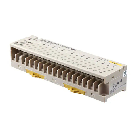
B7A Interface Unit NT-B7A16
Backlight (spare) NT30-CFL01 (for NT30)
NT30C-CFL01 (for NT30C)
Protective Sheets NT30-KBA04 (5 sheets/pack)
Battery C500-BAT08
This manual suits for next models
2
Table of contents
Other Omron Touch Terminal manuals

Omron
Omron NXR-ILM08C-EIT User manual

Omron
Omron NS - Owner's manual

Omron
Omron NT20M series User manual

Omron
Omron NT11 - 01-2004 User manual

Omron
Omron NV Series Owner's manual

Omron
Omron NS-CXDC1-V1 User manual

Omron
Omron NXR Series User manual

Omron
Omron NB-series Instructions for use

Omron
Omron NS - REV 04 User manual

Omron
Omron NT20 User manual

Omron
Omron ns series User guide

Omron
Omron NT631 Series User manual

Omron
Omron NT21 User manual

Omron
Omron NA-series User manual

Omron
Omron NT31 Series User guide

Omron
Omron DeviceNet DRT2-AD04 User manual

Omron
Omron NT11S User manual

Omron
Omron NS - 2 User manual

Omron
Omron NT30 User manual

Omron
Omron NT3S User manual