manuals.online logo
Brands
  1. Home
  2. •
  3. Brands
  4. •
  5. Omron
  6. •
  7. Touch Terminal
  8. •
  9. Omron NT2S-SF123B-E - Instruction manual

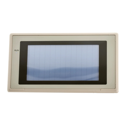
Omron NT2S-SF123B-E - Instruction manual

While writing this document, It is assumed that the user is well acquainted with the PLC
being used and with Windows based software usage, in general.
[Hereafter, in the manual, NT2S-SF123B-E will be referred to as NT2S C.]
General:
The NT2S C is intended to be used as a low cost Operator interface for PLCs which are rich in
program memory or data memory areas such as the Omron C Series PLCs.
The NT2S C has the following features:
Feature NT2S C
Display Backlit2X16LCD
LEDs 2
Keys 6
ASCII screens 32 characters
Embedded variables 16
Key definitions:
Each key is mapped from work bits I0201.00 to I0201.05. Every time a key is pressed, the
corresponding bit as shown in the table below is held on while the key is pressed. The keys also
have alternate functions.
Key Work Register mode function
Bit
F1/REG I0201.00 Changes register prefix
F2/DATA I0201.01 Enters data entry mode
F3/DOWN I0201.02 Increments register number or data depending on mode
F4/UP I0201.03 Decrements register number or data depending on mode
F5/CLR I0201.04 Clears data field to 0 / Register field to first register value
F6/ENT I0201.05 Accepts new data and sends to the PLC
Unit Operations:
The work bits I0200.00 to I0200.15 control the mode of operation of the unit as follows:
Work Bit Function
I0200.00 Controls LED0
I0200.01 Controls LED1
I0200.02 &
I0200.03 Not used
I0200.04 to
I0200.07 Reserved for future use
I0200.08 & 00 :Screen mode 01 :Register mode
I0200.09 10 :Operator mode 11 :Invalid
I0200.10 & Timeout to screen mode from Operator mode
I0200.11 00 :10 seconds 01 :20 seconds
10 :30 seconds 11 :40 seconds
I0200.12 to
I0200.14 Reserved for future use
I0200.15 To disable data entry in Screen mode
(ON : Disable)
From the above table, it is clear that the unit will display ASCII text (see section on Screens for
more details on this ) if I0200.08 and I0200.09 are OFF. To allow operators to view and edit the
registers, I0200.09 is to be kept ON. If I0200.09 is OFF, the unit will not display any registers and
the function keys will only act as push buttons mapped to the corresponding bits from I0201.00.
Refer to “Register Mode” for details. If I0200.09 is ON, REG key press will allow an operator to
view the registers. The REG key will scroll through the available register types whereas the UP
and DOWN arrow keys will scroll through the register/bit numbers. After timeout specified by bits
10 and 11 and if no key is pressed, the unit will switch back to the Screen mode and display
screens. Thus Operator mode is a combination of Register as well as Screen modes.
Screens :
The unit displays 32 characters from the PLC memory.
These characters are taken from the PLC data registers.
The unit tracks register DM0020 ( the Offset register ) in the PLC. The number in DM0020 gives
the start address of the data register block which contains the characters to be displayed. For
example, if DM0020 has number 124 in it, the unit will read 16 registers from DM0124, i.e. from
DM0124 to DM0139 and display the corresponding characters.
Each register contains two bytes. Each ASCII character to be displayed is one byte. So, each
word contains two characters that can be displayed. All the PLC ladder logic has to do is to put
the correct words in the registers being read by the unit so that a proper screen can be displayed.
As mentioned above, the starting address of the screen data block is controlled by the Offset
register, i.e. DM0020. Hence, there can be two methods of changing the screen to be displayed.
One is to keep the value in DM0020 constant and change the data in the screen registers in the
ladder logic. Second is to keep the screen text in the data memory (by editing DM registers) and
change the value in DM0020 so as to point to the correct memory address to display the desired
screen.
It is possible to embed registers in the screens. The unit reads 16 registers from DM0000 to
DM0015 (in which DM0012 to DM0015 are used for Bar Graph) in every scan. The data in these
registers can be embedded in the screens. To do so, use hex bytes 0 to B (C to F used for Bar
Graph) corresponding to register DM0000 to DM0011 respectively in the screen. Refer to the
example given which explains the embedding of registers.
It is possible to embed one data entry field in screens. It is similar to embedding register, only
instead of 0 to F use 10 to 1F hex bytes to address DM0000 to DM0015. The registers DM0000
to DM0015 can be edited with this feature one at a time in a screen.
Example 1: To display a static screen
Suppose the following screen needs to be displayed on the NT2S C :
Last Rinse Cycle
Water pump is on
To display this screen, do the following:
a. Move number 200 in DM0020 since the screen text will be stored in DM0200 onwards.
b. Move character string “Last Rinse Cycle” into 8 words from DM0200.
c. In a similar manner, the characters “Water pump is on” can be embedded into 8 words
from DM0208. (i.e. from DM0208 to DM0215)
This will put the following data in the data words below:
Word ASCIIHex Word ASCIIHex
DM0200 La 4C61H DM0208 Wa 5761H
DM0201 st 7374H DM0209 te 7465H
DM0202 R 2052H DM0210 r 7220H
DM0203 in 696EH DM0211 pu 7075H
DM0204 se 7365H DM0212 mp 6D70H
DM0205 C 2043H DM0213 i 2069H
DM0206 yc 7963H DM0214 s 7320H
DM0207 le 6C65H DM0215 on 6F6EH
Example 2: Embedding a variable in the screen
Suppose the following screen needs to be displayed :
Door: CLOSED
BAKETIME: 13.6s
Suppose the bake time is available in data word DM0100 and the oven status is given by bit
I001.00.
To display the above screen, do the following:
a. Move number 200 in DM0020 since the screen will be stored in DM0200 onwards.
b. Move character string “Door:” into 2 words, i.e. DM0200 and DM0201.
c. Move characters “OPEN” if bit I001.00 is ON or characters “CLOSED” if I001.00 is OFF.
d. In a similar manner, embed the characters “BAKETIME: ” into 5 words from DM0208.
e. NT2S C uses DM0000 to DM0011 registers for embedding data. Here we select
DM0003 to be used for embedding. So, move the data of DM0100 into DM0003 so that
embedding can be done.
f. Put 03032E03H in words DM0213 and DM0214. The NT2S C will read data in DM0003
and embed in xx.x format.
g. Move “s “ into DM0215. This command completes the screen by appending the “s ” to
the bake time.
This will put the following data in the data words below:
Word ASCII Hex Word ASCII Hex
DM0200 Do 446FH DM0208 BA 4241H
DM0201 or 6F72H DM0209 KE 4B45H
DM0202 : 3A20H DM0210 TI 5449H
DM0203 CL 434CH DM0211 ME 4D45H
DM0204 OS 4F53H DM0212 : 3A20H
DM0205 ED 4544H DM0213 0303H
DM0206 2020H DM0214 2E03H
DM0207 2020H DM0215 s 7320H
Register mode:
In the register mode, the operator can access all the registers and bits in the PLC.
By pressing the REG key, the operator can scroll through the register prefixes. By using the UP
or DOWN keys, the register numbers can be accessed. Data can be changed in the registers by
pressing the DATA key. The data field will blink to indicate that the unit is ready to accept new
data. At this time, the UP or DOWN keys can be used to edit data followed by the ENT key.
It is advisable to create a “password” screen which can block the usage of the register mode.
Bar Graph:
NT2S C uses DM0012 to DM0015 registers to hold bar graph values to be displayed. If Offset
register points to DM0200 then put Hex value 0C0C into DM0200 onwards to display bar graph
with the value in DM0012.
Example:
Put 0C0C into DM0200, DM0201, DM0202, DM0203 and 200 into DM0020. This will display bar
graph 8 characters wide. Maximum length is 16 characters. Each character on display can
display 5 vertical lines. To display full bar graph put # 80 into DM0012 and 0C0C from DM0200
to DM0207.
To display Bar Graph with value in DM0013, put 0D0D in DM0200 onwards.
Triggering screens :
As it can be seen from the above examples, there are two ways to display screens with NT2S C :
1. Keep all the message characters in the data memory ( the Omron PLCs have lot of data
registers which in most applications involving simple digital controls are not used anyway )
and simply change the offset register to display different screens.
The user can fill the data memory using the “data display editor” menu of the PLC programming
software.
2. Note that the data memory as well as the program memory can be used for embedding of
data.
Of course, a combination of the two methods can be used to optimise the memory usage.

Other Omron Touch Terminal manuals

Omron NT30 User manual

Omron

Omron NT30 User manual

Omron NT20M series User manual

Omron

Omron NT20M series User manual

Omron NT30C-ST141-E User manual

Omron

Omron NT30C-ST141-E User manual

Omron NT600M Series User manual

Omron

Omron NT600M Series User manual

Omron NA-series User manual

Omron

Omron NA-series User manual

Omron NT620S User manual

Omron

Omron NT620S User manual

Omron NA-series Instructions for use

Omron

Omron NA-series Instructions for use

Omron NT11 - 01-2004 User manual

Omron

Omron NT11 - 01-2004 User manual

Omron NT20 User manual

Omron

Omron NT20 User manual

Omron NA-series Operation and maintenance manual

Omron

Omron NA-series Operation and maintenance manual

Omron NS-CXDC1-V1 User manual

Omron

Omron NS-CXDC1-V1 User manual

Omron NT21 User manual

Omron

Omron NT21 User manual

Omron NT-series User manual

Omron

Omron NT-series User manual

Omron NS7 Series User guide

Omron

Omron NS7 Series User guide

Omron NT20S-ST121B-EV3 User manual

Omron

Omron NT20S-ST121B-EV3 User manual

Omron NB3Q-TW00B User guide

Omron

Omron NB3Q-TW00B User guide

Omron NS -  2 User manual

Omron

Omron NS - 2 User manual

Omron NA-series Instructions for use

Omron

Omron NA-series Instructions for use

Omron NS12 Instruction manual

Omron

Omron NS12 Instruction manual

Omron DeviceNet DRT2-AD04 User manual

Omron

Omron DeviceNet DRT2-AD04 User manual

Omron NSH5 User manual

Omron

Omron NSH5 User manual

Omron NA5-15*101 series User guide

Omron

Omron NA5-15*101 series User guide

Omron NA-series Instructions for use

Omron

Omron NA-series Instructions for use

Omron NA5-12W series Instructions for use

Omron

Omron NA5-12W series Instructions for use

Popular Touch Terminal manuals by other brands

Symbol PDT 7500 Series manual

Symbol

Symbol PDT 7500 Series manual

Motorola VT1000 user guide

Motorola

Motorola VT1000 user guide

keyto KT-PRO545-V1 quick start guide

keyto

keyto KT-PRO545-V1 quick start guide

Festo CPX-FB36 Electronics description

Festo

Festo CPX-FB36 Electronics description

EBN Technology TM50-5B-VU user manual

EBN Technology

EBN Technology TM50-5B-VU user manual

Avalue Technology RiPac-10P1 Quick reference guide

Avalue Technology

Avalue Technology RiPac-10P1 Quick reference guide

Datavan Glamor Series user manual

Datavan

Datavan Glamor Series user manual

Advantech-DLoG TREK-753 user manual

Advantech-DLoG

Advantech-DLoG TREK-753 user manual

Opzoon OFR-D1 manual

Opzoon

Opzoon OFR-D1 manual

Partner PT-6212-EB Service manual

Partner

Partner PT-6212-EB Service manual

Datalogic Joya X2 quick start guide

Datalogic

Datalogic Joya X2 quick start guide

Ingenico AXIUM RX5000 user guide

Ingenico

Ingenico AXIUM RX5000 user guide

Star RSR 28 brochure

Star

Star RSR 28 brochure

Response QM-3771 operating instructions

Response

Response QM-3771 operating instructions

Ingenico iwl255 Quick reference guide

Ingenico

Ingenico iwl255 Quick reference guide

CEP Terminals CT63 NG user manual

CEP Terminals

CEP Terminals CT63 NG user manual

Cooper Crouse-Hinds GHG 725 Series operating instructions

Cooper Crouse-Hinds

Cooper Crouse-Hinds GHG 725 Series operating instructions

Siemens 3TA2JG600PT operating instructions

Siemens

Siemens 3TA2JG600PT operating instructions

manuals.online logo
manuals.online logoBrands
  • About & Mission
  • Contact us
  • Privacy Policy
  • Terms and Conditions

Copyright 2025 Manuals.Online. All Rights Reserved.