ii
Table of Contents
■ Table of Contents ■
Introduction
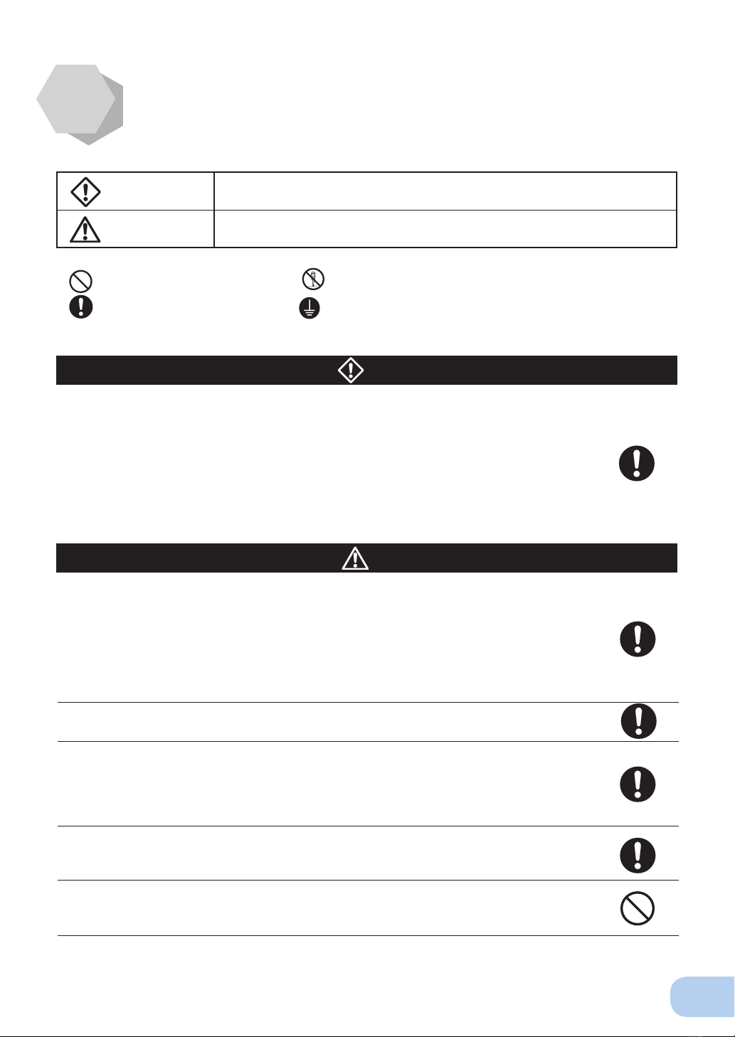
IMPORTANT SAFETY INSTRUCTION
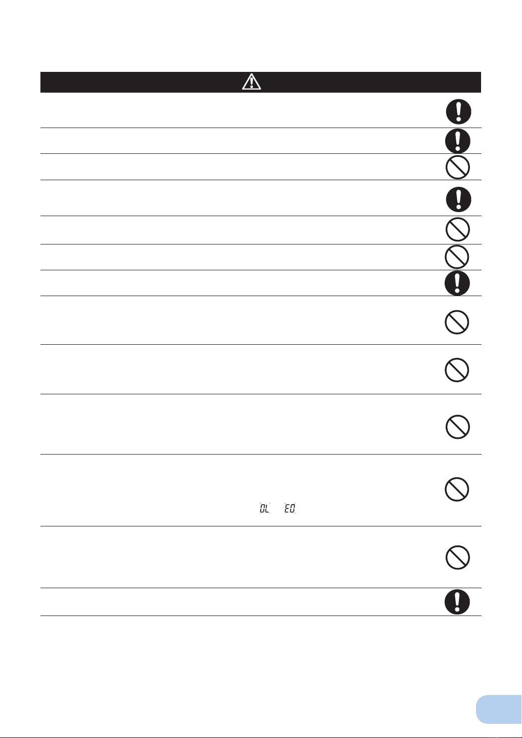
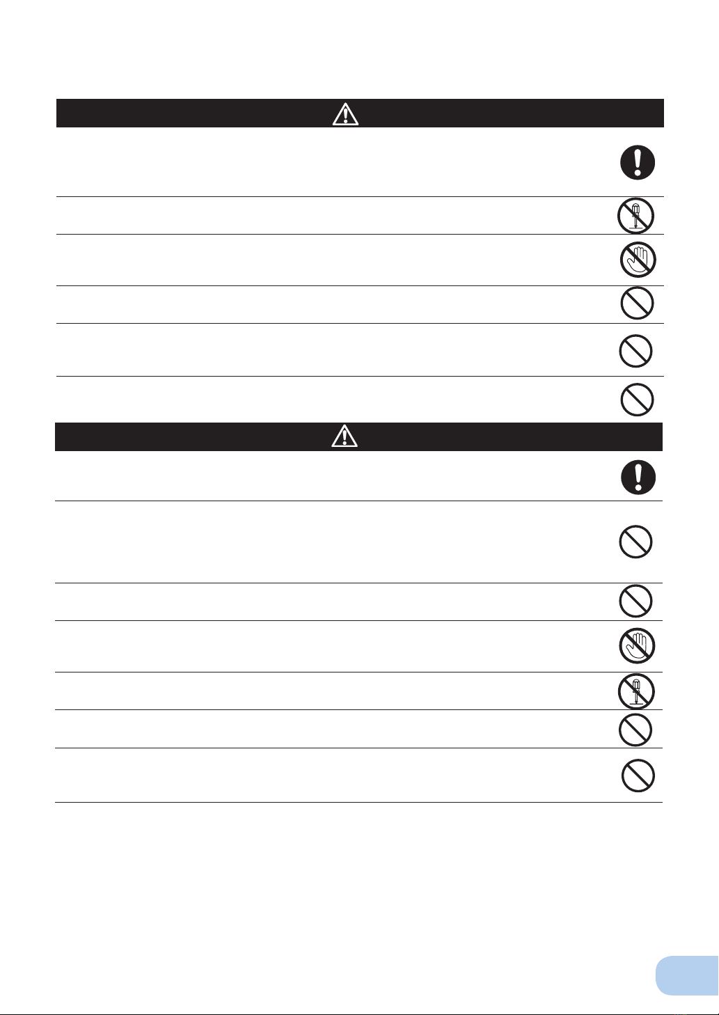
Safety precautions............................................................................................................................................. iii
1. Preparation .....................................................................................................................................................1
1-1 Unpacking the product........................................................................................................................1
1-2 Checking the contents.........................................................................................................................2
1-3 Name of each part...............................................................................................................................2
1-4 Explanation of symbols used on unit...................................................................................................4
2. Installation and connection ............................................................................................................................5
2-1 Precautions and notes on installation and connection........................................................................5
2-2 Installation and connection..................................................................................................................9
2-3 Connecting the equipment ................................................................................................................10
2-4 Checking the operation .....................................................................................................................13
2-5 Charging the battery..........................................................................................................................15
2-6 Measuring the initial value of backup time ........................................................................................15
2-7 Recharging the battery......................................................................................................................15
3. Operation......................................................................................................................................................16
3-1 Precautions and notes for operation .................................................................................................16
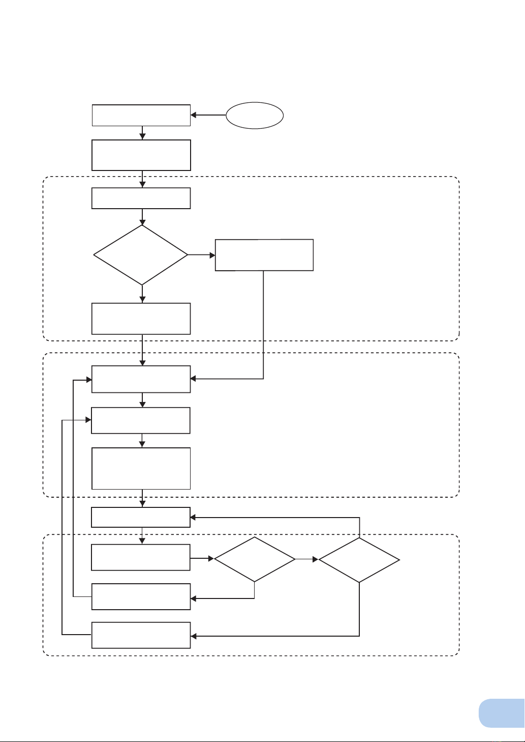
3-2 Start and stop procedures and basic operation................................................................................18
3-3 Interpreting beeps and displays........................................................................................................20
4. UPS functions...............................................................................................................................................23
4-1 Suspending a beep ...........................................................................................................................23
4-2 Testing the UPS (self-diagnostic test)................................................................................................23
4-3 Description of the auto battery test function......................................................................................24
4-4 Changing the setting of the functions................................................................................................24
5. Measuring the backup time........................................................................................................................29
5-1 How to measure backup time............................................................................................................29
5-2 Estimated backup time......................................................................................................................29
6. Maintenance and Inspection ......................................................................................................................31
6- 1 Checking the battery .........................................................................................................................32
6-2 Replacing the battery ........................................................................................................................32
6-3 Replacing the fan ..............................................................................................................................37
6-4 Cleaning ............................................................................................................................................38
7. Using the UPS monitoring software and contact signal...............................................................................39
7-1 When using the included UPS monitoring software to perform auto shutdown ................................40
7-2 When performing auto-save functions using the UPS service
in Windows Server 2003/XP/2000 + UPS service driver ...................................................................41
7-3 When performing auto-save functions using the standard UPS service
in Windows Server 2003/XP/2000/NT ................................................................................................42
7-4 Contact signal....................................................................................................................................47
8.Using an SNMP/Web card ............................................................................................................................ 53
8-1 Adding an SNMP/Web card ..............................................................................................................53
8-2 SNMP/Web card outline.....................................................................................................................54
9. Extending the backup time ..........................................................................................................................55
9-1 Connecting an additional battery unit (BU100SW/BU150SW only)...................................................55
10. Troubleshooting..........................................................................................................................................56
References .......................................................................................................................................................57
A. Specifications ........................................................................................................................................57
B. Dimensions ............................................................................................................................................58
C. Circuit block diagram ............................................................................................................................59
D. Related products ...................................................................................................................................60
E. List of UPS monitoring software functions .............................................................................................60


 Plus Startup manual")