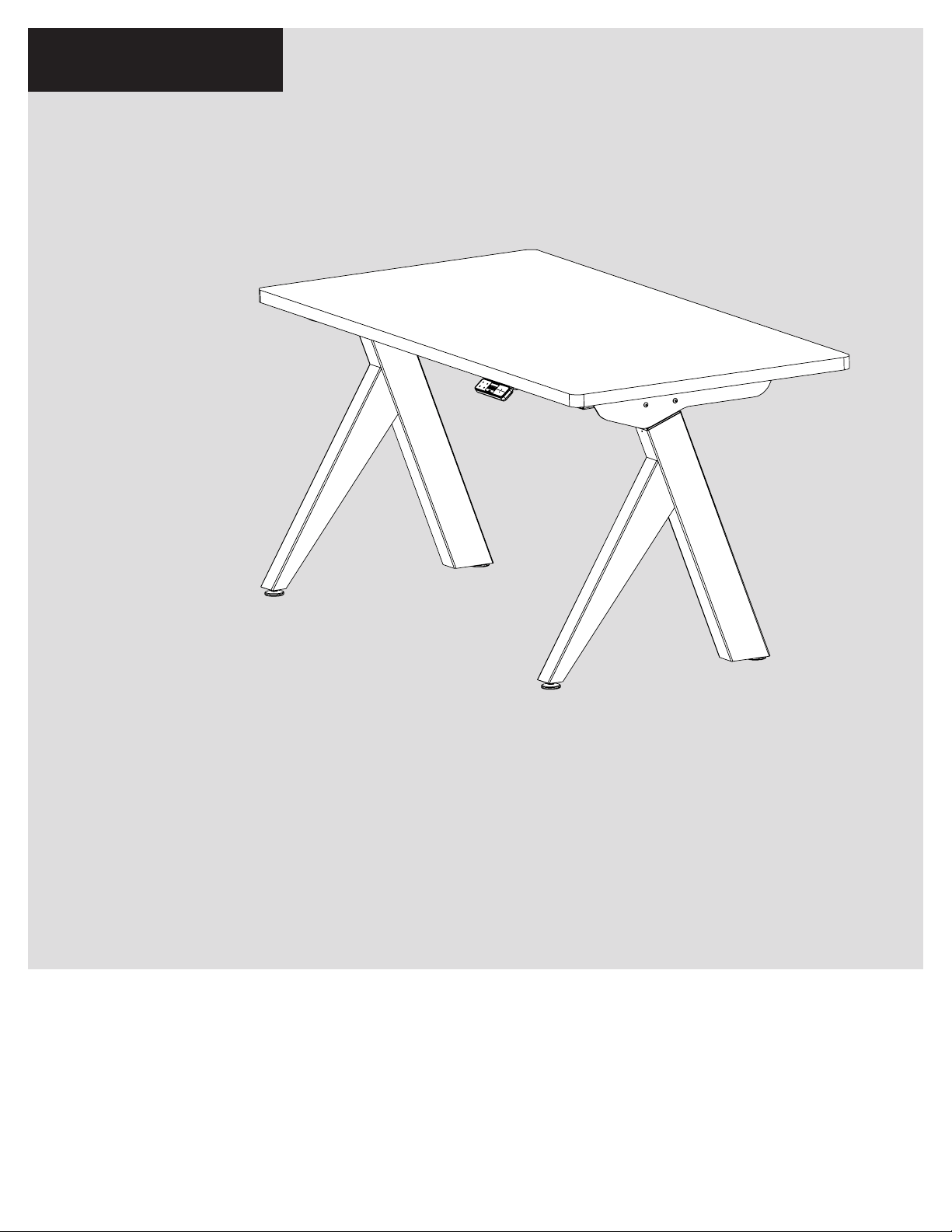
OMT-Veyhl OV1022 118101 User manual

USER GUIDE
OV1022 | Part No. 118101
OV1022
HEIGHT ADJUSTABLE TABLE

2 | OV1022
User Guide: OV1022
OV1022
HEIGHT ADJUSTABLE TABLE
FEATURES
• Full table base (add your own work surface)
• Over 150 color options
• Rated at 225 lb. load per two-column kit
• Integrated wire management
PRODUCT OVERVIEW

OV1022 | 3
User Guide: OV1022
Parts Diagram 4
Full Length 48" 4
Full Length 54"-72" 5
Safety Information 6-7
Assembly Instructions 8-12
Operation 13-14
Initialization and Reset 13
Handswitch Operation 13
Programmable Handswitch Operation 13
- Change the Height Unit 14
- Adjust Height Display 14
- Save Memory Position 14
- Recall Memory Position 14
Troubleshooting 15-16
Unit Errors 15
Handswitch Errors 16
Technical Data 17
Standards & Certications 18
TABLE OF CONTENTS
TABLE OF CONTENTS
This manual explains how this sit-stand desk is assembled, used, and maintained.
All sit-stand tables are subjected to functional and quality tests before leaving
our facility.

4 | OV1022
User Guide: OV1022
OV1022
PARTS DIAGRAM
1
3
7
8
9
6
5
4
2
10
PARTS Qty/Package
1. Column 2
2. Leg 2
3. Glide 4
4. 1- Piece J-Rail with Cable Tray 1
5. M6x12mm Screw 16
6. Top Support 2
7. Programmable Handswitch 1
8. Power Cord 1
9. Control Box 1
10. M8 Nut Hex 4
FULL LENGTH
For tables 48"
PARTS DIAGRAM

OV1022 | 5
User Guide: OV1022
OV1022
PARTS DIAGRAM
1
3
8
9
10
7
5
4
6
2
11
PARTS Qty/Package
1. Column 2
2. Leg 2
3. Glide 4
4. 3-Piece Adjustable J-Rail
with Cable Tray 1
5. M6x12mm Screw 20
6. M6 Wing Nut 4
7. Top Support 2
8. Programmable Handswitch 1
9. Power Cord 1
10. Control Box 1
11. M8 Nut Hex 4
FULL LENGTH
For tables 54"-72"
PARTS DIAGRAM

6 | OV1022
User Guide: OV1022
SAFETY
INFORMATION
INSTALL ONLY APPROVED WORK SURFACES
This table system does not include a work surface (desktop). Work surface must be at least ¾" thick and
weigh no more than 5 lb. per square foot (For example, a 2'x6' desktop should weigh no more than 60 lb).
Do not exceed a maximum weight for the desktop of 75 lb. To prevent table from tipping or collapsing,
make sure the desk frame is not overloaded by the weight of tabletop and objects you plan to put on the
table. If you are unsure, contact customer service.
KEEP AWAY FROM CHILDREN
This table system is not designed for use in homes or other areas accessible by small children.
For indoor commercial ofce use only.
BE CAREFUL WHEN ADJUSTING DESK HEIGHT
Body parts and property can be caught between the
moving work surface and an immobile obstacle (such as
shelves, furniture, window sills, or walls). Keep at least
one inch of clearance around desk and make sure nothing
is in table’s path for its entire range of motion.
Before raising or lowering:
• Check surroundings on all sides of desk are clear
• Make sure corded objects will not be pulled off table
or cause other objects to fall
• Make sure desk power cord moves freely
as desk moves up and down
IMPORTANT SAFETY INSTRUCTIONS Save these instructions.
DANGER
To reduce the risk of electric shock:
Always unplug this furnishing from the electrical outlet before cleaning.
WARNING:
To reduce the risk of death, serious injury, or property damage, read and
follow this safety information and the provided instructions when assembling this product.
Do not change or replace components and accessories provided by OMT-Veyhl.
SAFETY INFORMATION

OV1022 | 7
User Guide: OV1022
DO NOT OVERLOAD DESK
To prevent table from tipping or collapsing, make sure the desk frame is not overloaded by the weight
of tabletop and objects on table. Evenly distribute load; excess loads near edges can reduce stability
and lead to tip over.
• Do not exceed maximum load (including weight of desktop) of 225 lb. (102 Kg)
• Do not exceed edge load of 25 lb. when positioning monitors or mounting accessories.
• Do not sit or stand on table
USE CARE WHEN MOVING DESK
• Clear objects and equipment from table before moving to reduce the risk of tipping over.
• Adjust the desk to its lowest height before moving
• To disconnect, remove plug from outlet
• Do not move a loaded desk
DO NOT OPEN ELECTRICAL COMPONENTS
Do not attempt to service table components. There are no user-serviceable parts inside the motor control
units or table legs. If your table needs service, contact customer service. Never operate this workstation
if it has a damaged cord or plug.
KEEP TABLE FRAME DRY
Keep all electrical components away from water and high humidity. Clean only with a dry or
slightly damp cloth. Do not spray cleaning solutions directly onto table system.
GROUNDING INSTRUCTIONS
This product may be equipped with a cord having an
equipment-grounding conductor and a grounding plug.
Use only the cord provided. Make sure that the product
is connected to an outlet having the same conguration
as the plug (as shown in Illustration A) that is properly
installed and grounded in accordance with all local
codes and ordinances.
Do not modify the plug provided with the product
– if it will not t the outlet, have a proper outlet
installed by a qualied electrician.
No adapters are to be used with this product.
Keep cord away from heated surfaces.
SAFETY INFORMATION
Grounded
Outlet
Grounded Outlet Box
Grounding
Pin
Grounded
Outlet
Grounded Outlet Box
Grounding
Pin
ILLUSTRATION A

8 | OV1022
User Guide: OV1022
ASSEMBLY
INSTRUCTIONS
ASSEMBLY OVERVIEW
ASSEMBLY INSTRUCTIONS
The assembly of the table frame to be made in accordance with this manual.
Changes to the table frame or improper use may affect the safety, function, and life of your product.
This manual is for all sit-stand tables from the OV1022 series.
Due to different models or types, pictures may vary.
1. Assemble the top support to the column
2. Assemble the column to the j-rail
3. Assemble the leg to the column
4. Fasten the table frame onto the table top
5. Fasten the control box and handswitch to the table top
6. Connect the motor cables to the control box
7. Connect the handswitch (HS) cable to the control box
8. Connect the supplied power cord (AC) to the control box
9. Attach all cables to the cable tray
If you have any difculty assembling this unit or need to order
replacement parts, please contact our Customer Service department.
Use the parts diagrams on pages 4-5 as a reference.

OV1022 | 9
User Guide: OV1022
3-PIECE ADJUSTABLE J-RAIL
CABLE TRAY
(54"-72"tables)
ASSEMBLY INSTRUCTIONS
ASSEMBLE THE COLUMN TO THE J-RAIL
Assemble using the M6x12mm length screws
(2 per column). The maximum tightening torque
for these screws is 9.9Nm (7.3 ft-lbs)
2
ASSEMBLE THE TOP SUPPORT TO THE COLUMN
Assemble using the M6x12mm length screws
(2 per top support). The maximum tightening torque
for these screws is 9.9Nm (7.3 ft-lbs)
1
1-PIECE J-RAIL CABLE TRAY
(48"tables)

10 | OV1022
User Guide: OV1022
ASSEMBLY INSTRUCTIONS
ASSEMBLE THE LEG TO THE COLUMN
Assemble using the M8 hex nuts (2 per
leg). The maximum tightening torque
for these is 24Nm (17.7 ft-lbs).
3
PRE-INSTALL THE HEX NUTS
Partially install the M8 hex nuts
onto column studs (about halfway).
INSTALL LEG OVER THE HEX NUTS
Using keyhole openings, install the leg over the
hex nuts and slide studs into the small slots.
Tighten the hex nuts the rest of the way.
The maximun tightening torque for these
is 48Nm. (35 ft-lbs).
a
b
Column Studs
M8 Hex Nut
Leg Mounting Plate

OV1022 | 11
User Guide: OV1022 ASSEMBLY INSTRUCTIONS
FASTEN THE CONTROL BOX AND HANDSWITCH
TO THE TABLE TOP
Make sure the control box and handswitch are
fastened in a location where all the cables will
connect without being in tension. Be sure to
use approved screws per the table top supplier.
Recommended: mount control box in line with
cable tray in opening as shown.
5
DESK FRONT
(working side)
CONNECT THE MOTOR CABLES
TO THE CONTROL BOX
The motor cable plug-connection has to
click into place.
Connections to the control box:
M1-M2 = Connectors for the columns
HS = Connectors for the handset
AC = Connector for the power cord
6
FASTEN THE TABLE FRAME
ONTO THE TABLE TOP
Center frame on the table top, ensuring
that top supports are of equal distance from
the work surface's edge. Be sure to use
approved screws per the table top supplier.
Top supports should be mounted 3"from
front edge of work surface as shown.
4
3”
DESK FRONT
(working side)
center line

12 | OV1022
User Guide: OV1022
CONNECT THE HANDSWITCH (HS) CABLE
TO THE CONTROL BOX
7
CONNECT THE SUPPLIED POWER CORD (AC)
TO THE CONTROL BOX
ATTACH ALL CABLES TO THE TABLE TOP
AND/OR PLACE IN CABLE TRAY.
Attach cables in order to avoid any damage during
operation. Never attach cables and cords to legs.
8
9
ASSEMBLY INSTRUCTIONS

OV1022 | 13
User Guide: OV1022
OPERATION
INFORMATION
INITIALIZATION/RESET
The desk must be initialized/reset after any of the following:
- After assembly
- After disconnection from the power supply
- After any impact on the table top.
To initialize/reset, move the table to the lowest position by pressing the DOWN button on the handswitch until the
columns reach the lowest position. Press the DOWN button again until the table moves slightly down to the machine
zero point and back up to the operation zero point. Release the DOWN button. If the button is released too soon,
the table legs will not move up. Repeat the reset process.
The control box is programmed with a parameter le which controls the table legs’ lower and upper travel limits.
Under no circumstance should a control box from one table be moved to another.
NORMAL HANDSWITCH OPERATION (for all handswitch types)
By pressing the UP or DOWN buttons, the table will move up or down to the desired position. Once the
desired position is reached, let go of the UP or DOWN button. The table legs will stop once they reach
the lower or upper height limits.
PROGRAMMABLE HANDSWITCH OPERATION
This programmable handswitch is
equipped with a display for showing
the current table height in centimeters
or inches.
The handswitch also will display an error code if an error is detected by the control box. When an error
is detected, the display will show an error code “EXX,” instead of the current table height. To resolve the
error, see the Troubleshooting Section (p. 15-16 of this guide).
The programmable handswitch also has the ability to save up to four different height positions.
OPERATION INFORMATION

14 | OV1022
User Guide: OV1022
PROGRAMMABLE HANDSWITCH OPERATION (continued)
CHANGE THE HEIGHT UNIT (inches or centimeters)
The handswitch can display the table height in either centimeters or inches. With the help of the
S5-menus, the unit of measure can be changed.
To change the unit of measure, follow these steps:
1. Press and hold the 1, 2, and UP buttons until the display shows “S 5”.
2. Conrm by pressing the “S” button. Now the display will have changed.
To exit the menu without making a selection, wait until the height display appears again.
CHANGE THE HEIGHT DISPLAY
If the displayed value does not match the actual height of the table top, the display can be corrected
as follows:
1. Press and release the “S” button.
2. Press and hold the DOWN button until the display starts to ash.
3. Change the height shown on the handswitch by pressing the UP or DOWN button to the desired height.
Conrm by pressing the “S” button.
To exit the menu without making a selection, wait until the height display appears again.
SAVE MEMORY POSITION
1. Move the table up or down to the desired height.
2. Press the “S” button (in the display “S -” is shown.)
3. Select a position by pressing one of the four number buttons, 1-4, (the display will show the setting
as “S1”).
4. The saved position is conrmed by a double click sound from the control box. The display shows the
current table height. Repeat steps to save a maximum of four different positions.
RECALL MEMORY POSITION
Press and hold the desired memory button (1, 2, 3 or 4) the table moves from the current position into
the saved position. The button must be pressed until the position is reached. If the button is released,
the table will stop short of the desired height.
OPERATION INFORMATION

OV1022 | 15
User Guide: OV1022
UNIT
ERROR CODE
SOURCE SOLUTION
Table does not
move
No power supply Plug in the power cord or check the connection
on the control box
No connection or a loose
connection to the drives
Verify the plug connections of the motor cable
to the control box
No connection or a loose
connection to the handswitch
Verify the plug connections of the motor cable
to the control box
Max lifting capacity
is exceeded
Reduce the weight or load on the desktop
Replace the handswitch
Max time limit is exceeded Control is activated automatically after approx. 9 minutes
Defective drive Contact customer service
Defective control box Contact customer service
Defective handswitch
Contact customer service
Defective drive
Table moves
down at a
slow rate
Control box expects
new reset Reset control box. (See page 13)
During operation,
tables moves at
a slow rate
Max lifting capacity
is exceeded Reduce weight
Table moves
on one side only
briefly and then
stops
No connection or a loose
connection to the drives
Verify the plug connections of the motor cable
to the control box and reset the control box
TROUBLESHOOTING
TROUBLESHOOTING

16 | OV1022
User Guide: OV1022
HANDSWITCH DISPLAY
ERROR CODE
SOURCE SOLUTION
HOT
E00
E01
E02
The control box monitors the duty
cycle (time-controlled) and its max
temperature. A value has been exceeded.
Wait until the “HOT” display goes out - the table is working properly again
M1 – Internal Fault
Unplug and contact customer service
M2 – Internal Fault
M3 – Internal Fault
E12
E13
E14
M1 – Defect
Unplug.
Correct the external short circuit and/or verify the cable to the drives.
Plug cables into the control box and re-run table.
M2 – Defect
M3 – Defect
E36
E37
E38
M1 – Not connected
Motor not connected.
Check cable / connector to the drive.
Reset the table (see page 13).
M2 – Not connected
M3 – Not connected
E24
E25
E26
M1 – Overcurrent
If the problem still exists, please contact customer service
If necessary, reduce the load on the table
Reset the table (see page 13)
Option ISP function. Remove source.
M2 – Overcurrent
M3 – Overcurrent
Collision resolve if necessary
E55
E56
E60
Drive 1 - Synchronization is lost
Drive 2 - Synchronization is lost
Collision identified
E48
E49
Overcurrent drive 1
Overcurrent drive 2
Max load exceeded remove excess load from the table
The connection to the drive is interrupted or a new drive is connected.
Reset the table (see page 13).
E61 Drive replaced
If it is not possible to resolve an error as described, disconnect the power cord, wait a few minutes and reset the table again.
If the error still occurs, remove the table from the power source and contact customer service.
(Error Code list is valid from rmware 1.7.5 and higher)
TROUBLESHOOTING

OV1022 | 17
User Guide: OV1022
TECHNICAL DATA
ILLUSTRATION A
TECHNICAL DATA
GENERAL CONTROL BOX
Power supply 120 VAC ±10% / 60 Hz
Maximum input current 5 A
Standby power consumption, primarily <0.3 W
Operating temperature 0-35°C
Protection class IP 20
Maximum duty cycle 5% (1 min. on / 18 min. off)
Maximum power output (rated) 240 watts
TWO-COLUMN FRAME WITH CONTROL BOX
Maximum lift capacity 211 lb (≈ 96kg / 941N)
Adj. range 18in (444mm) View Illustration A
[46in]
1165mm
[28in]
721mm

18 | OV1022
User Guide: OV1022
INTERTEK LISTING BELONGS TO: System: Lambda
OMT-Veyhl USA
11511 James Street
Holland, MI 49424
CONTACT YOUR SALES REPRESENTATIVE FOR WARRANTY INFORMATION
WARRANT Y
The drive system is tested according to the following standards:
Meets BIFMA X5.5 2014.
CUSTOMER SERVICE
End of life cycle: Once product is disassembled, all steel components can be recycled at your local
metal collector. For products with electronic components, see Disassembly Guide.
STANDARDS &
CERTIFICATIONS

OV1022
USER GUIDE
Part No. 118101
Rev A | Rev 022020
Table of contents
Other OMT-Veyhl Indoor Furnishing manuals

OMT-Veyhl
OMT-Veyhl OV1008 User manual

OMT-Veyhl
OMT-Veyhl OV1001 User manual

OMT-Veyhl
OMT-Veyhl OV1019 User manual

OMT-Veyhl
OMT-Veyhl Clever benching User manual

OMT-Veyhl
OMT-Veyhl Clever User manual

OMT-Veyhl
OMT-Veyhl OV1001 Installation instructions

OMT-Veyhl
OMT-Veyhl OV1018 User manual

OMT-Veyhl
OMT-Veyhl OV1000 User manual

OMT-Veyhl
OMT-Veyhl UNIVERSAL WORK SURFACES User manual

OMT-Veyhl
OMT-Veyhl OV1024 User manual