ON Semiconductor LV8702VSLDGEVK User manual

©Semiconductor Components Industries, LLC, 2018
August, 2018 −Rev. 0
1Publication Order Number:
EVBUM2575/D
LV8702VSLDGEVK
Stepper Motor Driver
Module Solution Kit
Quick Start Guide
Overview
The LV8702VSLDGEVB is an ON Semiconductor motor driver
module featuring the LV8702V. This module is capable of easily
driving a stepper motor.
Motor driving is made easy with Arduino Micro1) compatibility.
The LV8702VSLDGEVB comes with a Baseboard for facilitated
plug−and−play connectivity with an Arduino Micro.
GUI and Open−source API Functions are available for custom,
user−specific motor driving programs.
Features
•VCCmax = 36 V, IOmax = 2.5 A2)
(between OUT_A and B, between OUT_C and D)
•24 V Applications Recommended (VCC = 9~32 V Max)
•Rotation of the Motor is Controlled by a Single Pulse Signal, which
is Advantageous for Smooth Driving (Micro−step) and Rotating
at High Speed Rotation
•4 Patterns can be Set for Full, Half (2 Patterns) and Quarter Step
•High−efficiency Drive that Adjusts the Current to the Optimum
Current according to the Motor Load and Rotational Speed
(in Half, Quarter Step Setting)
•The Reduction of Power Consumption, Heat Generation,
Vibration and Noise is Achieved
•User−friendly GUI Allows Operation Check and Sample Program
Generation
For further product information, please visit:
http://www.onsemi.com/PowerSolutions/product.do?id=LV8702V
1) Arduino/Genuino are trademarks registered by Arduino AG.
2) Stress exceeding this voltage or current may risk damage to the device. Functionality and reliability may be hindered if the device exceeds
these values. The maximum current value, IOmax, does not guarantee the module can handle that much current. If the device overheats,
thermal shutdown will occur.
www.onsemi.com
Figure 1. LV8702VSLDGEVB Board
EVAL BOARD USER’S MANUAL
Figure 2. ONBB4AMGEVB Board with
Arduino Micro and LV8702VSLDGEVB
Board

LV8702VSLDGEVK
www.onsemi.com
2
WHAT YOU NEED
•PC
Recommended OS: Windows 7/Windows 10, 64 bit
Connected to the Internet
(Only for “Including the TimerOne Libary” on Page 3)
Arduino IDE 1.8.4 3) Installed
User with an Administrator rights
•Power Supply
AC Adapter Output voltage: 9~32 V
Output current: ~5 A
Connector specification
Polarization: Positive Center
Inner diameter = 2.1 mm, outer diameter = 5.5 mm
Recommended: WSU120−1000 (Triad Magnetics)
or stabilized DC power supply, dry cell battery, etc.
CONTENTS OF THE KIT
Hardware
•LV8702VSLDGEVB: Motor driver module
•ONBB4AMGEVB: Baseboard
•Arduino Micro
•USB Cable (Micro B−A)
•Flat−tip Screw Driver
•Stepper motor MDP−35A
(Nidec Seimitsu, Step angle= 7.5 deg, 12 V/ 300 mA) 1 pc
Software
All of the following files are included in LV8702VSLDGEVK Software (English) that is available on the website of the
following links.
http://www.onsemi.com/PowerSolutions/evalBoard.do?id=LV8702VSLDGEVK
. . . Arduino IDE Installer
. . . GUI as well as .NET Framework4.6.1 Installer
. . . .NET Framework4.6.1 Related Files
. . . API Library
. . . GUI −Arduino Firmware
3) Contents of kit may not be compatible with different versions. Please see the Appendix attached if specified version is not installed

LV8702VSLDGEVK
www.onsemi.com
3
Software Setup
Please download
LV8702VSLDGEVK_SOFTWARE.ZIP and expand
to any
directories (E.g. Libraries\Documents or Desktop).
API Library
The following process should be operated with the
Arduino Micro disconnected.
1. Double click on the Arduino sketch for GUI
This will launch the Arduino IDE.
(Check the Appendix, “Arduino IDE Installation”,
if the Arduino IDE is not installed)
The IDE will display the following message when
the LV8702_Program.ino file is opened for the
first time. Click “OK” to continue.
This message will be displayed if the .ino file is
not inside of a folder with the same name.
(E.g. Sketch12345.ino must be in the Sketch12345
folder).
2. Include the API Library
As shown below, navigate to “Sketch →Include
Library →Add .Zip Library”
The following window will appear. Select the
“LV8702_APILibrary” folder, and open this folder
as shown below.
Click the folder only once and push “Open”
button.
Do not double click the folder.
Unless updating the function library, including the API
function library only needs to be done once.
Including the TimerOne Library
As shown below, navigate to “Sketch →Include Library
→Manage Libraries”
Once the library manager starts up, please type
“TimerOne” in the search bar at the top.
*Some screen captures are taken from different motor driver modules

LV8702VSLDGEVK
www.onsemi.com
4
Select and install “TimerOne” in the search results
Compiling the Arduino Program
・Write to Arduino
1. Select the Arduino board to upload to by
navigating to “Tools →Board →
Arduino/Genuino Micro”.
2. Write an Arduino sketch and navigate to
“Sketch →Verify/Compile” when finished
writing.
The IDE will display “Done compiling” after
a successful compile has been verified.
3. Connect the PC to the Arduino Micro via USB
and select the corresponding COM port as shown
below.
4. Upload the sketch by clicking “Sketch →Upload”
or by pressing the button.
In the process of uploading, the Arduino Micro
bootloader will be installed.
The IDE will display “Done uploading” after
a successful upload to the Arduino.
Sketches written to the Arduino will not be erased
unless rewritten.
If the uploading of the program fails confirm the
details in step 1 check board name and step 3
check serial port connection.

LV8702VSLDGEVK
www.onsemi.com
5
Rewrite the Arduino Program
In the case of 1. or 2. below, please rewrite the program to
the Arduino
1. When updating the API Function library.
a) Delete the existing API function library by
navigating to Documents\Arduino\libraries and
deleting the LV8702_APILibrary folder.
b) Include the latest API function library. Please
save the latest API function library in your
preferred directory on your PC.
(See Page 3, “Software Setup”)
Include the latest API function library.
(See Page 3 “API Library”)
c) Compile and write the program to the Arduino
(See Page 4, “Compiling the Arduino program
SWrite to Arduino”)
2. When evaluating the LV8548 DC and other motor
driver modules.
(Assuming other motor driver module libraries
have already been included)
a) Compile and write the program to the Arduino
(See Page 4, “Compiling the Arduino program
SWrite to Arduino”)
If you are testing the any other motor driver module
library for the first time, please operate according to their
corresponding manual.
GUI Installation
1. Double click on in the
folder and proceed
with the installation as shown below.
*If a previous version of this GUI
(ON_MD_Module_Kit_GUI) has already been
installed and the most recent GUI will be installed,
please overwrite and update the existing GUI.
(No need for uninstallation)
2. The .NET Framework4.6.1 installation window
will appear if the PC does not have the necessary
version. If .NET Framework4.6.1 is not installed,
click Accept to install.
The following window shows the installation in progress.
(This may take several minutes)
If the installation requires a reboot to complete, a message
will appear on the screen. Please press “Yes” to reboot.
Once rebooted, run installation file again.

LV8702VSLDGEVK
www.onsemi.com
6
3. Install the GUI
Press “Next”
4. Specify installation folder, or just click “next” to
continue with the installation
Please press “next”.
User administrative rights may be required for
installation. If an alert for user account control is displayed,
please select “Yes.”
The following screen will be displayed after a successful
installation.
Make sure the GUI shortcut icon is created on the desktop
as shown below and that the program has been added to the
Windows start menu.
Desktop Shortcut
Start Menu

LV8702VSLDGEVK
www.onsemi.com
7
Hardware Setup
1. Connect the LV8702VSLDGEVB (Motor Driver
Module) to the ONBB4AMGEVB (Motor Driver
Baseboard). Insert the module into the baseboard,
while being careful not to bend the header pins
2. Connect the Arduino/Genuino Micro to the
baseboard, as seen in the figure above. The USB
connection port should be labeled on the
baseboard “←USB” to dictate the orientation of
the Arduino
1.
2.
3. Plug in the motor wires (Insulation between 5 mm
– 10 mm) into the output terminals on the
baseboard – OUT_A/B/C/D (CN5). Firmly fix the
wires by screwing down the terminals with
a flat−heat screwdriver. Refer to the table below
for motor connectivity:
OUT_A A (Blue)
OUT_B A (White)
OUT_C B (Yellow)
OUT_D B (Red)
Motor Wiring
Diagram
(Do not worry about incorrect wiring. Incorrect wiring
will NOT cause any damage to hardware.)
4. Connect the Arduino to a PC using a USB cable
5. Insert the AC Power adapter into the DC Jack on
the baseboard. Be sure that a Center positive type
adapter is being used with an output voltage
9~32 V
If using power supply cables, please connect the
positive terminal to VCC and the negative terminal
to GND in the CN6 connector. The power supply
terminals +/−at CN6 are polarity sensitive.
(VCC = +, GND = −)
4.
CN6
CN5
5.
3.

LV8702VSLDGEVK
www.onsemi.com
8
How to Use the GUI
15 16 17
18 119 21 20
32
12 13
6
5
87
4
910
11
18
14
1. Double−click the GUI shortcut located on the
desktop and connect the COM serial port
Available COM ports will appear in the
drop−down box.
If the Arduino is connected correctly to the PC, an
option for “Arduino Micro (COMx)” will be
available (where x is the number associated with
the port); select that COM port and click connect.
2. After connecting the Arduino, the GUI will
automatically navigate to the LV8702 tab
3. Set the chip enable function
As LV8702V to the chip enable function
This function switches between Standby and
Operating modes.
[Operation] …Operating mode
[Standby] …Standby mode
4. Specify the desired motor excitation and direction
of rotation
Excitation
(Excitation Method) One−step Rotation Angle
Full step 1/1 Step angle
Half step (Full−torque) 1/2 Step angle
Half step (Smooth) 1/2 Step angle
Quarter step 1/4 Step angle
The following table compares LV8702 data sheet
notation.
GUI Notation Data Sheet Notation
Full step Full step
Half step (Full−torque) Half step full−torque
Half step (Smooth) Half step
Quarter step Quarter step

LV8702VSLDGEVK
www.onsemi.com
9
Direction:
CW −Clockwise
CCW −Counter clockwise
NOTE: The direction of rotation may vary depending on
how the motor wires are connected to the
terminals.
5. Set the output motor current
The output current can be set within the limit value
(Box on the right) according to 10 by operating the
slider or the value of Box on the left.
The setting values are incremented by 0.01 A, but
the accuracy is limited due to the specifications of
the Arduino.
NOTE: The output current is set to 0.3 [A] for the
reference motor and the recommended adapter
at startup, and it is not necessary to set it again
for use in the same environment.
6. Set the step angle for the motor
NOTE: The step angle will vary depending on the
motor. If using the included reference motor,
please set it to 7.5°.
The step angle setting enables the “rpm” setting under
Motor Speed and “Degree” setting under Transfer Unit.
7. Set the motor speed in step/s or rpm
step/s (=pps): Frequency of the number of steps per second
rpm: Rotational speed of the motor per minute
Stepper motors are not intended for sudden acceleration,
and will vibrate if the control exceeds the maximum rotation
speed. When using the included reference motor with the
recommended AC adaptor, please set the rotation speed
according to the table below.
Full step 1~560 step/s 2~700 rpm
Half step
(Full−torque)
1~1120 step/s 1~700 rpm
Half step
(Smooth)
Quarter step 1~2240 step/s
8. Set the units and value of the transfer condition for
the control signal. After the specified transfer
condition elapses, the motor will stop and hold its
torque. Since current continues to flow to the
motor, it is important to pay attention to heat
generation. Please select the Free button to stop
powering the motor.
For an unspecified rotation time, select 0 (Infinity)
Example 1: Rotating the motor for 10 seconds
Transfer Unit = Seconds
Transfer Time = 10 [seconds]
Example 2: Rotating the motor for 100 steps
Transfer Unit = Steps
Transfer Step = 100 [steps]

LV8702VSLDGEVK
www.onsemi.com
10
xample 3: Rotating the motor 180 degrees
Transfer Unit = Degree
Transfer Angle = 180 [degree]
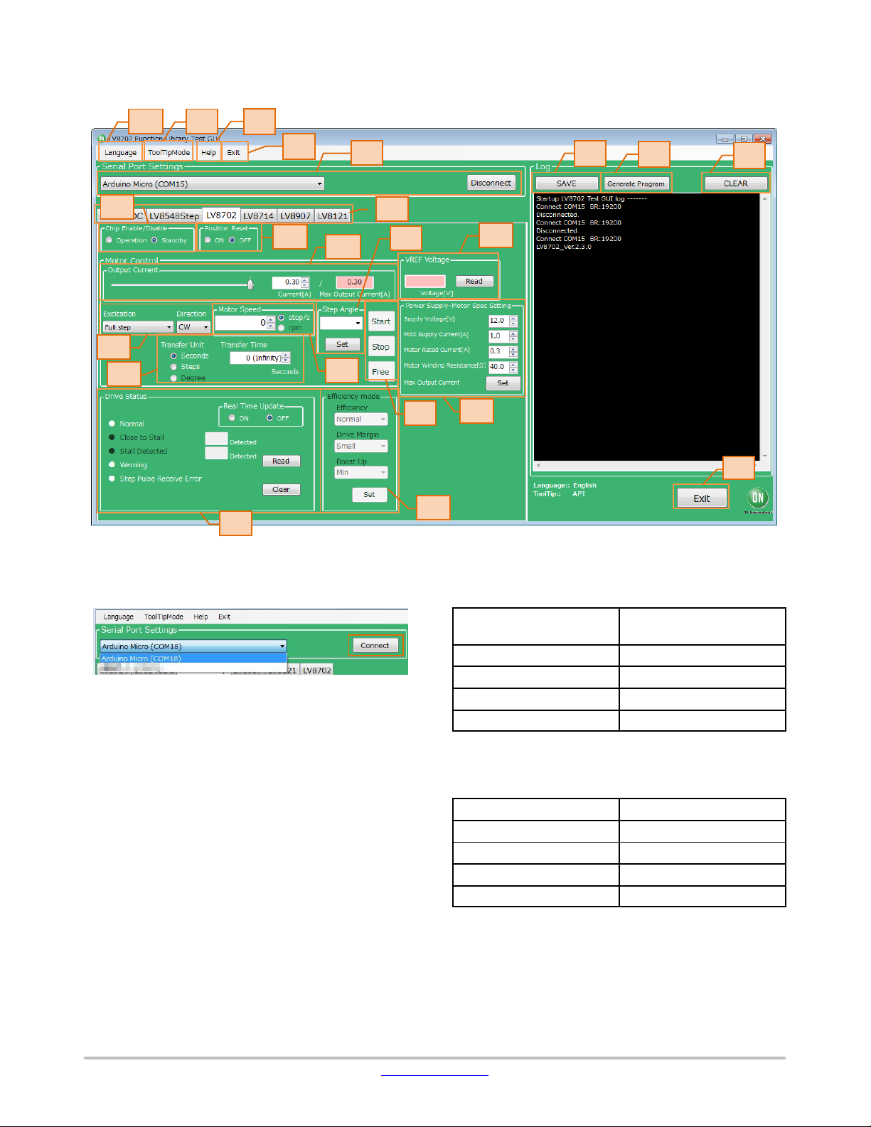
9. When the Start button is pressed, the motor will
rotate. If changes to the Output Current, Excitation
or Motor Speed are made, the changes will take
effect upon pressing the Start button.
To change the direction of rotation, it is
recommended to stop the motor first with the Stop
button, change the value, and then press the Start
button to begin the motor rotation.
Pressing the Stop button causes the motor to stop,
and hold the torque.
When the Free button is pressed, the motor will
stop and lose the torque.
To maintain the position while the motor rotates,
or to pause the motor and restart from the same
position, select the Stop button.
At this time, because of the current still flowing
to the motor, attention must again be paid to
heat generation.
10. Set the specifications of the power supply and
motor to be used.
Supply Voltage... Power supply voltage
MAX Supply Current... Maximum power supply
current
Motor Rated Current... Motor Rated Current
Motor Winding Resistance... Motor coil resistance
Max Output Current Set buttons ... Calculate the
maximum output current from the above four
setting values, and 5 limit the set range of the
output motor current to enable safer motor driving.
11. Set the high−efficiency drive function.
(This function does not work in slow speed and
fast speed range where the feedback signal can’t
be stably detected. This function cannot be
selected when Full Step is set.)
The high−efficiency drive function automatically
optimizes the motor current according to the motor
load and rotational speed. By turning on this
function, power consumption, heat, vibration, and
noise can be reduced. The high−efficiency drive
function consists of the following three
parameters.
Efficiency... ON/OFF of high−efficiency drive
function
When the high−efficiency drive function is turned
on, the motor current is automatically adjusted
within the range of the limit set in 5.
Drive Margin... Margin adjuster Function
Adjust the margin from the minimum current that
can rotate the motor.
When the margins are set to Small, the current
consumption is the smallest, but the number of
boost−ups may be increased for small
load−changes.
For this reason, set the margin to be larger for
applications with excessive load variation.
Drive Margin
Current
Consumption Robustness
Small Low
Normal
Weak
Strong
Middle
Large
Boost Up... boost−up adjuster function
This process increases the motor current rapidly
and temporarily in order to maintain the motor
rotation in response to load variation.
Increasing the boost increases the rush load
resistance, but increasing the boost increases the
rotational stability.
The worsened of rotational stability can be
suppressed by increasing the Drive Margin.
Boost Up Robustness
Rotational
Stability
Min Weak
Strong
Stable
Unstable
Low
High
Max
12. Set the reset function.
The reset function resets the excitation position
and locks the motor.
[ON] ... Reset ON
[OFF] ... Reset OFF
Neither is turned off the power.
13. Voltage reading function
14. Status check function
15. GUI Language Settings
16. GUI Tool Tip Display
17. Help function
(See Appendix for more information)

LV8702VSLDGEVK
www.onsemi.com
11
18. Closing the GUI
When finished, exit the GUI by pressing the “Exit”
button at the bottom right of the screen or by
clicking “Exit” item at the top menu bar.
The following popup message will be displayed when
exiting the GUI.
Select “Yes” to quit the GUI.
Select “No” to cancel the exit and return to the main
screen.
If the GUI is closed while the motor is still running, the
motor will be stopped and the window will close.
For more details on the following features, refer to the
next section on How to use the GUI Log:
19. Saving the GUI Log
20. Clear the GUI Log
21. Program Generation

LV8702VSLDGEVK
www.onsemi.com
12
How to Use the GUI Log
The log screen in the GUI shows the serial data sent to
Arduino to control its API functions.
i. Set Step Angle
ii. Start Motor
Rotation
Executed
iii. Stop Motor
Rotation
Executed
iv. Free Motor
Rotation
Executed
19 2021
i. Set Step Angle
Executed
ii. Start Motor Rotation
iii. Stop Motor Rotation
iv. Free Motor Rotation
19. Saving the GUI Log
By pressing the “SAVE” button, the content
displayed on the work log can be saved as a .txt
file or a .csv file.
20. Clear GUI Log
By pressing the “CLEAR” button, the content
displayed on the work log will be erased.
21. Program Generation
Pressing the “Generate Program” will output the
executed API functions on the work log into a .ino
program file that can be uploaded directly with
Arduino. By writing the output of the .ino file to
Arduino, motor control can be executed
automatically through standalone operation
according to the procedure generated through the
GUI Log.
For more details regarding the Arduino program
generation function, refer to the attached Appendix
under 21 Arduino Program Automatic Generation.

LV8702VSLDGEVK
www.onsemi.com
13
APPENDIX
Arduino IDE Installation
1. Run installer that are
included in.ZIP files downloaded from our web
site.
(To avoid software from not operating properly,
please use this version and refrain from updating)
2. Read through and agree to the terms and
conditions during the setup by clicking the
“I Agree” button.
3. Leave the following default components to install
as is and press “Next”.
4. Set the install directory and press “Install”.
5. If prompted, please install the Arduino USB
Drivers
nArduino USB Driver
nGenuino USB Driver
nlibusb−win32
nAdafruit Industries LLC Port (COM and LPT)
nLinino Port (COM and LPT)
6. Below shows a completed installation for the
Arduino IDE. Feel free to click “Close”.
789101112

LV8702VSLDGEVK
www.onsemi.com
14
Supplemental GUI Content
The following step numbers correspond to the step
numbers in the “How to use the GUI” section in the Quick
Start Guide.
13. Voltage Reading Function
READ to display the voltages in the pink column.
VREF …Output Motor Current Reference Voltage
Displays the reference voltage for 5 Output motor
current setting
VREF = (Output Motor current) ×5 ×0.22 W
14. Status Check Function
The red lamps and counters indicate the status
detected by the LV8702 from the outputs of each
terminal (DST1, DST2, MONI) of the LV8702.
When the Real Time Update is turned on, the
outputs from the terminals are periodically Read
and displayed.
Close to Stall and Stall Detected are enabled when
the high−efficiency drive function is set to
Efficiency = High, and the number of times of
occurrence is displayed in boxes.
This count is reset by pressing Clear.
(Maximum count = 255)
When the Real Time Update is turned off, the
status when the Read button is pressed is
displayed.
Normal:
Normal conditions (DST1:H, DST2:H)
Close to Stall:
Electrical detection of danger of stall
(DST1:H, DST2:L)
Stall Detected:
Electrical detection of stall state
(DST1:L, DST2:H)
Warning:
Detects the state of short−circuit between the OUT
terminal and the power supply and GND of the
OUT terminal and the IC overheat state
(DST1: L, DST2: L).
Step Pulse Receive Error:
Detects (MONI) positional deviation of the motor
caused by noise−jumping into the STEP input
terminal of the LV8702.
About Warning:
When the overheat protection function is activated,
all OUTs turn OFF and the motor stops.
When the temperature drops, the Warning state is
released and the motor drive is restarted.
When the short−circuit protection function of the
OUT terminal is activated, all OUTs are turned
OFF and the motor stops.
This condition can be reset by switching Chip
Enable/ Disable from Operation to Standby to
Operation.
15. GUI Language Settings
Languages can be changed from the menu on the
top left of the window.
Motor driver tab languages are not changed.
(Please see tool tip for translations)
Motor driver tabs are set to
English

LV8702VSLDGEVK
www.onsemi.com
15
16. GUI Tool Tip Display
The GUI sends serial data to execute API
functions in the Arduino through USB.
With the API Hints turned on, hover over different
buttons and settings to display descriptions and
functions associated with that item.
The API hints can be turned off by navigating
through the ToolTipMode menu at the top of the
window
17. Help Function
From the help menu, it is possible to view GUI
and API version information, as well as serial
communication details.
Selecting About will display the following
window.
Product name
GUI version
API version
Selecting SerialPort will display the overview of
serial communication. 181920
21. Arduino Program Automatic Generation
When using the GUI, automatically generated
Arduino code will be output to the log window.
It is possible to export the code to an Arduino
sketch (.ino) file that can be used with the Arduino
IDE.
Once the automatically generated code is imported
into the Arduino IDE, it is possible to mimic the
procedures from the GUI.
1) Generating and writing Arduino code
Pressing Generate Program will open a save file
dialog.

LV8702VSLDGEVK
www.onsemi.com
16
Please select the desired directory for the file to be
saved (e.g. Desktop or Documents) and click Save.
When using the GUI,
is the name of the program, so a different name
will need to be used to save the exported file.
Double click the newly saved Arduino program to
open the Arduino IDE.
The GUI and Arduino IDE cannot be connected to
a PC at the same time. To upload the Arduino
program, please exit or select Disconnect in the
GUI, and proceed working in the Arduino IDE.
Follow the instructions in the Quick Start Guide in
P3 “Compiling the Arduino Program – Write to
Arduino”.
2) Using the generated Arduino program
After each API operation in the generated
program, a delay(0) is inserted. By changing the
value of the argument (0)* to the delay function,
the user is able to freely adjust the rotation time,
as well as the interval time between each API call
execution. This can be used to achieve the desired
stand−alone operation.
*Parameter units are msec (1000th of a second).
For a delay of 1 second, use delay(1000).
[Example of changing the interval time]
NOTE
“motorRotationDeg(10, 720.0, 0, 0)”
will start the motor with Full step, CW, 10 Step/s,
and an angle of 720 deg
“delay(5000)”
will drive the motor for 5000[msec]
(5s)
“motorRotationStop()”
will stop the motor
After the time specified in the delay command has
elapsed, the next command will be executed.
If the delay setting is 0 or too short, some motor
operations will complete so quickly, that it will be
imperceptible.
NOTE: The delay setting at the beginning of the setup
method will execute in the case of a new USB
connection, Arduino reset, or upon uploading
a sketch to the Arduino. In this case, the
Arduino will delay for 5 seconds while writing
the initial settings.

LV8702VSLDGEVK
www.onsemi.com
17
BOARD SCHEMATIC (1/2)
1SWOUT
2CP2
3CP1
4GMG2
5GMG1
6GAD
7FR
8STEP
9ST
10 RST
11 ADIN
12 MD2
13 MD1
14 VREG5
15 DST2
16 DST1
17 MONI
18 OE
19 SST
20 CHOP
21 VREF
22 SGND 23
GST2
24
GST1
25
PGND2
26
OUT2B
27
OUT2B
28
VM2
29
VM2
30
RF2
31
RF2
32
OUT2A
33
OUT2A
34
OUT1B
35
OUT1B
36
RF1
37
RF1
38
VM1
39
VM1
40
OUT1A
41
OUT1A
42
PGND1
43
VG
44
VM
45 TP
IC1
LV8702V_SSOP44J
R4
RES_1005
R3
RES_1005
C5
CAP_1005
C4
CAP_1005
R5
RES_1005
R6
RES_1005
R7
RES_1005
R8
RES_1005
R9
RES_1005
R10
RES_1005
R11
RES_1005
R12
RES_1005
R13
RES_1005
R14
RES_1005
JP1
JUMPER_1005
C2
CAP_1005
C3
CAP_1005
C6
CAP_1005
R15
RES_1005
C7
CAP_1005
R16
RES_1005
R17
RES_1005
R1
RES_6432
R2
RES_6432
C1
CAP_50TZV 10M5X6.1
R18
RES_1005
R19
RES_1005
R20
RES_1005
R21
RES_1005
1
2
3
4
5
6
7
8
9
10
11
12
CN2
61301211121
Wurth Electronik
1
2
3
4
5
6
7
8
9
10
11
12
CN1B
Wurth Electronik
61302421121
JP2
JUMPER_1005
JP3
JUMPER_1005
R22
RES_1005 C8
CAP_1005
1
2
3
4
5
6
7
8
9
10
11
12
CN1A
JP4
JUMPER_1005
CN1B−2
CN1B−1
CN1B−3
CN1B−4
CN1B−10
CN1B−12
CN1B−6
CN1B−7
CN1B−8
CN1A−9
CN1A−8
CN1A−7
CN1B−9
CN1A−6
CN1A−10
CN1A−2
CN1B−11
CN1A−5
CN1A−11
CN2−3
CN2−2
CN2−4
CN2−1
CN2−5
CN2−1
CN2−2
CN2−3
CN2−4
CN2−5
CN1B−1
CN1B−2
CN1B−3
CN1B−4
CN1B−5
CN1B−6
CN1B−10
CN1B−7
CN1B−8
CN1B−9
CN1B−5
CN1B−11
CN1B−12
CN1A−5
CN1A−6
CN1A−7
CN1A−8
CN1A−9
CN1A−10
CN1A−11
CN1A−2
Figure 3. LV8702VSLDGEVB Schematic

LV8702VSLDGEVK
www.onsemi.com
18
Table 1. LV8702VSLDGEVB BILL OF MATERIALS
Designator Qty. Description Value Tolerance Footprint Company Part Number
IC1 1 Motor Driver − − SSOP44J ON semiconductor LV8702V
R1−2 2 Thick Film Resistor 0.22 W,1 W ±5% 6432(2512Inch) KOA SR73W3AT**R22J
R3 1 Thick Film Resistor 15 kW, 0.1 W ±5% 1005(0402Inch) KOA RK73B1ET**153J
R4 1 Thick Film Resistor 100 kW, 0.1 W ±5% 1005(0402Inch) KOA RK73B1ET**104J
R5−11,
R18−19
9Thick Film Resistor 47 kW, 0.1 W ±5% 1005(0402Inch) KOA RK73B1ET**473J
R12−14, R16 4Thick Film Resistor 47 kW, 0.1 W ±5% 1005(0402Inch) KOA RK73B1ET**473J
R15 11 Thick Film Resistor 12 kW, 0.1 W ±5% 1005(0402Inch) KOA RK73B1ET**123J
R17 1 Thick Film Resistor 15 kW, 0.1 W ±5% 1005(0402Inch) KOA RK73B1ET**153J
R20 1 Thick Film Resistor 100 kW, 0.1 W ±5% 1005(0402Inch) KOA RK73B1ET**104J
R21 1 Thick Film Resistor TBD, 0.1 W ±5% 1005(0402Inch) TBD
R22 1 Thick Film Resistor 27 kW, 0.1 W ±5% 1005(0402Inch) KOA RK73B1ET**273J
JP1−3 3 Jumper 0W, 1 W ±20% 1005(0402Inch) KOA RK73Z1ET**
JP4 1 Jumper 0W, 1 W ±20% 1005(0402Inch) KOA RK73Z1ET**
C1 1 VCC Bypass Capacitor 10 mF, 50 V ±20% 5 x 5.5 Wurth Electronik 865080642006
C2, C3, C5,
C6, C8
5Ceramic multilayer
Capacitor
0.1 mF, 100 V ±10% 1005(0402Inch) Murata Manufacturing GRM155R62A104KE14D
C4 1 Ceramic multilayer
Capacitor
1000 pF, 50 V ±5% 1005(0402Inch) Murata Manufacturing GRM1555C1H102JA01J
C7 1 Ceramic multilayer
Capacitor
150 pF, 50 V ±10% 1005(0402Inch) Murata Manufacturing GRM1555C1H151JA01J
CN1A, 1B 1Pin header to baseboard 12 pins x 2 −30.48 x 5.08 Wurth Electronik 61302421121
CN2 1 Pin header to baseboard 12 pins −30.48 x 2.54 Wurth Electronik 61301211121
PCB 1 PCB −30.48 x 20.32
NOTE: Parts highlighted in yellow are not mounted at the time of product shipment.

LV8702VSLDGEVK
www.onsemi.com
19
BOARD SCHEMATIC (2/2)
Figure 4. ONBB4AMGEVB Board Schematic
Wurth Electronik
Wurth Electronik
Wurth Electronik Wurth Electronik
SULLINS_Connector_Solutions
Wurth Electronik
Wurth Electronik
Wurth Electronik
694106301002
Wurth Electronik
PPPC171LFBN−RC
PPPC171LFBN−RC
ON Semiconductor
61301221821
61301211821
691243110004 691243110004
691214110002S
691243110004
DC JACK
61300411121
1
2
CN6
1
2
3
4
CN7
1
2
3
4
CN5
1
2
3
4
CN8
1
2
3
4
5
6
7
8
9
10
11
12
CN4
1
2
3
4
5
6
7
8
9
10
11
12
13
14
15
16
17
CN1
1
2
3
4
5
6
7
8
9
10
11
12
13
14
15
16
17
CN2
1
2
3
4
5
6
7
8
9
10
11
12
CN3
1
2
3
4
5
6
7
8
9
10
11
12
1
2
3
4
J2
1
2
3
J1
D1
MBR230LSFT1G
V+
OUT_D
OUT_C
OUT_B
OUT_A
A5
A4
A3
A2
OUT_A
OUT_B
OUT_C
OUT_D
V+
D4
D5
D6
D7
IO8
IO9
IO10
IO11
IO12 IO13
+5V
D2
D3
A5
A4
A3
A2
A1
A0
OUTE
OUT_F
OUT_G
OUT_H
OUTE
OUT_F
OUT_G
OUT_H
3V3
MOSI SCK
MISO
D2
D3
D4
D5
D6
D7
IO8
IO9
IO10
IO11
IO12
IO13
MOSI
SCK
MISO
+5V
A5
A4
A3
A2
A1
A0
3V3
+5V
TX
RX
TX
RX
V-
V-
V+
Table 2. BASEBOARD BILL OF MATERIALS
Designator Qty. Description Value Tolerance Footprint Company Part Number
D1 1 Diode − − SOD123 ON Semiconductor MBR230LSFT1G
CN1,2 2 Arduino Micro connector − − ∅1.02 x17 −2.54 pitch Hirosugi−Keiki FSS−41085−17
CN3 1 Module connector − − ∅1.02 x12 x2lines −2.54 pitch Wurth Electronik 61302421821
CN4 1 Module connector − − ∅1.02 x12 −2.54 pitch Wurth Electronik 61301211821
CN5,7,8 3 Motor connectors − − ∅1.1 x4 −3.5 pitch Wurth Electronik 691243110004
CN6 1 Power connectors − − ∅1.1 x2 −3.5 pitch Wurth Electronik 691214110002S
J1 1 DC barrel jack − − 9.0 x 14.5 Wurth Electronik 694106301002
J2 1 UART pin headers − − ∅1.1 x4 −2.54 pitch Wurth Electronik 61300411121
C1 1 Electrolytic capacitor 100 mF, 50 V ±10% −Wurth Electronik 860020674015
PCB 1 PCB − − 80 x 60
NOTE: When using a custom−made baseboard, be sure to mount an electrolytic capacitor equivalent to C1 between VCC and GND.
Neglecting to install this capacitor may lead to damage and malfunction of any connected driver modules.

LV8702VSLDGEVK
www.onsemi.com
20
ON Semiconductor and are trademarks of Semiconductor Components Industries, LLC dba ON Semiconductor or its subsidiaries in the United States and/or other countries.
ON Semiconductor owns the rights to a number of patents, trademarks, copyrights, trade secrets, and other intellectual property. A listing of ON Semiconductor’s product/patent
coverage may be accessed at www.onsemi.com/site/pdf/Patent−Marking.pdf. ON Semiconductor reserves the right to make changes without further notice to any products herein.
ON Semiconductor makes no warranty, representation or guarantee regarding the suitability of its products for any particular purpose, nor does ON Semiconductor assume any liability
arising out of the application or use of any product or circuit, and specifically disclaims any and all liability, including without limitation special, consequential or incidental damages.
Buyer is responsible for its products and applications using ON Semiconductor products, including compliance with all laws, regulations and safety requirements or standards,
regardless of any support or applications information provided by ON Semiconductor. “Typical” parameters which may be provided in ON Semiconductor data sheets and/or
specifications can and do vary in different applications and actual performance may vary over time. All operating parameters, including “Typicals” must be validated for each customer
application by customer’s technical experts. ON Semiconductor does not convey any license under its patent rights nor the rights of others. ON Semiconductor products are not
designed, intended, or authorized for use as a critical component in life support systems or any FDA Class 3 medical devices or medical devices with a same or similar classification
in a foreign jurisdiction or any devices intended for implantation in the human body. Should Buyer purchase or use ON Semiconductor products for any such unintended or unauthorized
application, Buyer shall indemnify and hold ON Semiconductor and its officers, employees, subsidiaries, affiliates, and distributors harmless against all claims, costs, damages, and
expenses, and reasonable attorney fees arising out of, directly or indirectly, any claim of personal injury or death associated with such unintended or unauthorized use, even if such
claim alleges that ON Semiconductor was negligent regarding the design or manufacture of the part. ON Semiconductor is an Equal Opportunity/Affirmative Action Employer. This
literature is subject to all applicable copyright laws and is not for resale in any manner.
PUBLICATION ORDERING INFORMATION
N. American Technical Support: 800−282−9855 Toll Free
USA/Canada
Europe, Middle East and Africa Technical Support:
Phone: 421 33 790 2910
EVBUM2575/D
LITERATURE FULFILLMENT:
Literature Distribution Center for ON Semiconductor
19521 E. 32nd Pkwy, Aurora, Colorado 80011 USA
Phone: 303−675−2175 or 800−344−3860 Toll Free USA/Canada
Fax: 303−675−2176 or 800−344−3867 Toll Free USA/Canada
Email: [email protected]
ON Semiconductor Website: www.onsemi.com
Order Literature: http://www.onsemi.com/orderlit
For additional information, please contact your local
Sales Representative
◊
This manual suits for next models
1
Table of contents
Other ON Semiconductor Control Unit manuals