Weco Multi Power 184 User manual

Cod. 006.0001.1380
08/09/2021 V.2.8
Multi Power 184
Instruction manual
ENG
Translation of original instructions

WELD THE WORLD
Cod. 006.0001.1380
08/09/2021 V.2.8 Multi Power 184
2
ENGLISH

WELD THE WORLD
Cod. 006.0001.1380
08/09/2021 V.2.8
Multi Power 184
3
ENGLISH
INDEX
1 INTRODUCTION.......................................................................................................................................... 4
1.1 PRESENTATION.......................................................................................................................................... 5
2 INSTALLATION .......................................................................................................................................... 6
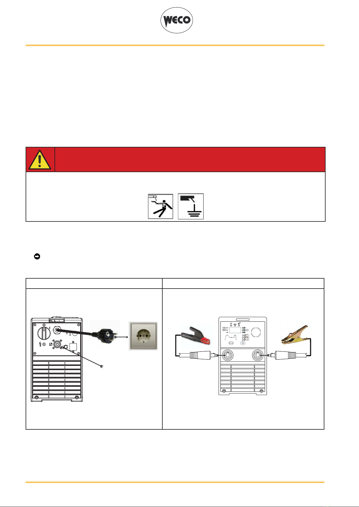
2.1 CONNECTIONS TO THE MAINS POWER SUPPLY .................................................................................. 6
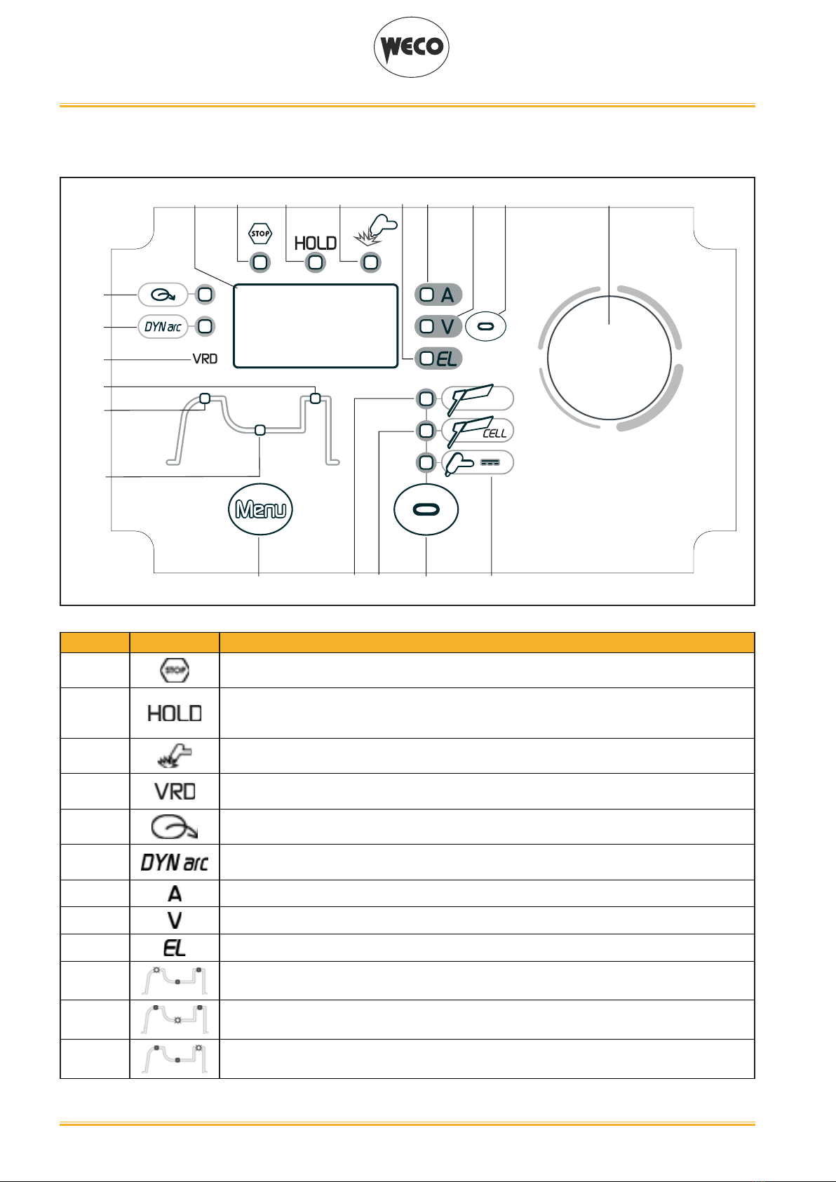
2.2 FRONT PANEL............................................................................................................................................. 6
2.3 REAR PANEL............................................................................................................................................... 7
2.4 PREPARING FOR MMA WELDING............................................................................................................. 8
2.5 PREPARING FOR TIG WELDING ............................................................................................................... 9
3 USER INTERFACE .................................................................................................................................... 10
4 UNIT POWER-UP ...................................................................................................................................... 11
5 RESET (LOAD FACTORY SETTINGS)..................................................................................................... 13
6 ALARM MANAGEMENT ........................................................................................................................... 14
7 DERATING................................................................................................................................................. 15
8 ELECTRODE WELDING (MMA)
CELLULOSE WELDING (MMA CEL) ....................................................................................................... 16
8.1 MMA / MMA CEL WELDING - FIRST LEVEL MENU ................................................................................ 16
8.2 MMA / MMA CEL WELDING - SECOND LEVEL MENU ........................................................................... 18
9 DC TIG WELDING ..................................................................................................................................... 20
9.1 DC TIG WELDING - FIRST LEVEL MENU ................................................................................................ 20
9.2 TIG DC WELDING - SECOND LEVEL MENU ........................................................................................... 21
10 TORCH TRIGGER PROCEDURE ............................................................................................................. 22
11 TECHNICAL DATA .................................................................................................................................... 23
12 WIRING DIAGRAM.................................................................................................................................... 25
12.1 REMOTE CONTROL CONNECTOR (back panel)..................................................................................... 26
13 SPARES..................................................................................................................................................... 27

WELD THE WORLD
Cod. 006.0001.1380
08/09/2021 V.2.8 Multi Power 184
4
ENGLISH
1 INTRODUCTION
IMPORTANT!
This handbook must be consigned to the user prior to installation and commissioning of the unit.
Read the "General prescriptions for use" handbook supplied separately from this handbook before
installing and commissioning the unit.
The meaning of the symbols in this manual and the associated precautionary information are given in
the "General prescriptions for use”.
If the "General prescriptions for use" are not present, it is mandatory to request a replacement copy
from the manufacturer or from your dealer.
Retain these documents for future consultation.
LEGEND
DANGER!
This pictogram warns of danger of death or serious injury.
WARNING!
This pictogram warns of a risk of injury or damage to property.
CAUTION!
This pictogram warns of a potentially hazardous situation.
INFORMATION!
This pictogram gives important information concerning the execution of the relevant operations.
This symbol identies an action that occurs automatically as a result of a previous action.
This symbol identies additional information or a reference to a dierent section of the manual
containing the associated information.
§ This symbol identies a reference to a chapter of the manual.
*1 The symbol refers to the associated numbered note.
NOTES
The gures in this manual are purely guideline and the images may contain dierences with respect to
the actual equipment to which they refer.

WELD THE WORLD
Cod. 006.0001.1380
08/09/2021 V.2.8
Multi Power 184
5
ENGLISH
1.1 PRESENTATION
Multi Power 184 is an inverter DC TIG/MMA portable welding power source.
The sturdiness of the components of this unit makes it a reliable working companion for workshop and
outdoor applications.
The available DC TIG functions and digital control make this unit ideal for maintenance, building con-
struction, and light metalwork.
In MMA welding the Hot Start and Arc Force functions are adjustable and they allow improved arc strik-
ing, a atter bead and more uniform weld.
The Anti Sticking function makes it possible to detach the electrode rapidly from the workpiece in the
event of accidental sticking.
Up to 4,00mm diameter electrode welding is possible in MMA.
The power source is designed to guarantee safety and exibility through the following features:
OVERCUT: in case of over-voltage in the supply line, the supply to the power source is cut o.
The overcut protection protects electronic parts of the machine against damage caused by voltage
surges.
CURRENT AUTO-CALIBRATION: the power source works at a supply voltage ranging between
115V~±15%/50-60Hz and 230V~±15%/50-60Hz.
The maximum value of the adjustable welding current is automatically limited based on the supply volt-
age measured when the power source is switched on.
DERATING: Derating limits current during welding when supply voltage drops below the limit value of
190Vac.
This limits current input so as not to overload the inverter and keeps the welding arc stable.
FANS: Fan speed varies based on power source internal temperature measured by thermal sensors.
This function brings the following improvements:
- reduction of noise.
- reduction of dust extracted (cleaner equipment, less maintenance).
The welding modes and procedures available are those indicated in the table.
MODE PROCEDURE
MMA
CELLULOSE
TIG CONTINUOUS 2 STROKE LIFT-ARC (2T)
Accessories that can be connected to the unit:
• manual remote control for remote adjustment of the welding current.

WELD THE WORLD
Cod. 006.0001.1380
08/09/2021 V.2.8 Multi Power 184
6
ENGLISH
2 INSTALLATION
DANGER!
Lifting and positioning
Read the warnings highlighted by the following symbols in the “General prescriptions for use”.
2.1 CONNECTIONS TO THE MAINS POWER SUPPLY
The characteristics of the mains power supply to which the equipment shall be connected are given in
the chapter entitled “TECHNICAL DATA”.
The machine can be connected to motor-generators provided their voltage is stabilised.
Connect/disconnect the various devices with the machine switched o.
2.2 FRONT PANEL
2 1
○ Negative pole welding socket.[Item 1].
○ Positive pole welding socket.[Item 2].

WELD THE WORLD
Cod. 006.0001.1380
08/09/2021 V.2.8
Multi Power 184
7
ENGLISH
2.3 REAR PANEL
1
3
2
4
○ Welding power source ON/OFF switch [Item 1].
○ Remote control connector [Item 2].
○ Warning LED for overcut protection triggering [Item 3].
○ Power cable. [Item 4].
• Total length (including internal part): 2.5 m
• Number and cross section of wires: 3 x 2.5 mm2
• Type of plug supplied: Schuko

WELD THE WORLD
Cod. 006.0001.1380
08/09/2021 V.2.8 Multi Power 184
8
ENGLISH
2.4 PREPARING FOR MMA WELDING
1. Set the welding power source ON/OFF switch to “O” (unit o).
2. Plug the power cable plug into a mains socket.
3. Choose the electrode based on the type of material and thickness of the workpiece to be welded.
4. Insert the electrode in the electrode holder.
5. Connect the electrode holder clamp plug to the following welding socket: Positive pole welding
socket.
6. Connect the earth clamp plug to the following welding socket: Negative pole welding socket.
7. Connect the earth clamp to the workpiece being processed.
DANGER!
Electric shock hazard!
Read the warnings highlighted by the following symbols in the “General prescriptions for use”.
8. Set the welding power source ON/OFF switch to “I” (unit on).
9. Select the following welding mode on the user interface: MMA
10. Set the required welding parameter values on the user interface.
When the remote control [RC] is connected and enabled, the welding current can be adjusted.
The system is ready to start welding.
REAR VIEW FRONT VIEW
RC
REMOTE
CONTROL

WELD THE WORLD
Cod. 006.0001.1380
08/09/2021 V.2.8
Multi Power 184
9
ENGLISH
2.5 PREPARING FOR TIG WELDING
1. Set the welding power source ON/OFF switch to “O” (unit de-energized).
2. Plug the power cable plug into a mains socket outlet.
3. Connect the gas hose from the welding gas cylinder to the rear gas connection.
4. Open the cylinder gas valve.
5. Connect the gas hose of the welding torch to the front gas connection.
6. Connect the electrode holder clamp plug to the following welding socket: Negative pole welding
socket.
7. Choose the electrode based on the type of material and thickness of the workpiece to be welded.
8. Insert the electrode in the TIG torch.
9. Connect the earth clamp plug to the following welding socket: Positive pole welding socket.
10. Connect the earth clamp to the workpiece being processed.
11. Set the welding power source ON/OFF switch to “I” (unit powered).
12. Select the following welding mode on the user interface: DC TIG
13. Use the ow control valve to adjust the ow of gas as required while the gas is owing out.
14. Set the required welding parameter values on the user interface.
When the remote control pedal is connected and the relative locking screw is tightened the
welding current will vary in relation to the pressure exerted on the pedal.
The system is ready to start welding.
REAR VIEW FRONT VIEW
RC
REMOTE
CONTROL

WELD THE WORLD
Cod. 006.0001.1380
08/09/2021 V.2.8 Multi Power 184
10
ENGLISH
3 USER INTERFACE
L1 L2 L3
L4
L5
L6
L7 L8L9
L10
L11
L12
L13 L14 L15
D1 S1
S2 S3
E1
CODE SYMBOL DESCRIPTION
L1 This LED illuminates to show an anomaly in the operating conditions.
L2
When this LED illuminates the last voltage and current average values measured during wel-
ding are shown on following displays: D1
The “HOLD” function is cleared when a new weld is started or when any setting is changed.
L3 This LED illuminates to conrm the presence of power on the output sockets.
L4 Illumination shows that the following function has been activated: reduction of the output vol-
tage (U0)
L5 This LED indicates that the current reference setting is imposed by the remote controller.
L6 DC TIG mode: Illumination shows that the following function has been activated: DYNAMIC
ARC
L7 Illuminates to show a value in the following unit of measurement: AMPERES
L8 Illuminates to show a value in the following unit of measurement: VOLTS
L9 When this LED illuminates the following parameter can be set: ELECTRODE TYPE
L10 When this LED illuminates the following parameter can be set: HOT-START
L11 When this LED illuminates the following parameter can be set: WELDING CURRENT
L12 When this LED illuminates the following parameter can be set: ARC FORCE

WELD THE WORLD
Cod. 006.0001.1380
08/09/2021 V.2.8
Multi Power 184
11
ENGLISH
L13 This LED illuminates to show that the following welding mode is selected: MMA
L14 This LED illuminates to show that the following welding mode is selected: CELLULOSE
L15 This LED illuminates to show that the following welding mode is selected: TIG CONTINUOUS
D1
Parameters/functions setting: The display shows the selected parameter.
Welding: The display shows the eective amperes or volts value during welding.
HOLD function: The display shows the current of voltage average values of the last welding
process.
E1 Parameters/functions setting: The encoder provides the facility to alter the selected parameter.
Welding: The encoder allows the welding current to be modied.
S1
Parameters/functions setting: This button selects the parameter to be shown on the following
display: D1
Possible choices:
-(A) Preset welding current
-(V) No-load voltage
-(EL) Preset type of electrode
Welding: This button selects the parameter to be shown on the following display: D1
Possible choices:
-(A) Eective welding current
-(V) Eective welding voltage
HOLD function: This button selects the parameter to be shown on the following display: D1
Possible choices:
-(A) Average welding current
-(V) Average welding voltage
S2 Press the button once to select the parameters of the rst level menu.
Hold down the button for 3 seconds to gain access to the second level menu.
S3 This button selects the welding mode.

WELD THE WORLD
Cod. 006.0001.1380
08/09/2021 V.2.8 Multi Power 184
12
ENGLISH
4 UNIT POWER-UP
Set the welding power source ON/OFF switch to “I” to switch on the unit.
FX.X The message appears on the following display: D1.
x.x= software version
First power-up or power-ups following a RESET procedure
The welding power source sets up for welding with the factory preset values.
Subsequent power-ups
The welding power source sets up for welding in the latest stable welding conguration that was active
at the time of power-o.
The power source works at a supply voltage ranging between 115V~±15%/50-60Hz and 230V~±15%/50-
60Hz.
The maximum value of the adjustable welding current is automatically limited based on the supply vol-
tage measured when the power source is switched on.
SUPPLY VOLTAGE CURRENT RANGE THAT CAN BE
SET (MMA)
CURRENT RANGE THAT CAN BE
SET (TIG)
115 V~ ±15 % / 50 - 60 Hz 10 A – 115 A 5 A - 115 A
230 V~ ±15 % / 50 - 60 Hz 10 A – 180 A 5 A - 200 A

WELD THE WORLD
Cod. 006.0001.1380
08/09/2021 V.2.8
Multi Power 184
13
ENGLISH
5 RESET (LOAD FACTORY SETTINGS)
L1 L2 L3
L4
L5
L6
L7 L8L9
L10
L11
L12
L13 L14 L15
D1 S1
S2 S3
E1
AA
ACTIVATION
The reset procedure involves complete restoration of the default values, parameters and memory set-
tings set in the factory.
All memory locations will be reset and hence all your personal welding settings will be lost!
The reset procedure is useful in the following cases:
- Too many changes made to the welding parameters so user nds it dicult to restore defaults.
- Unidentied software problems that prevent the welding power source from functioning correctly.
A
○ Set the welding power source ON/OFF switch to “O” to switch the unit o.
○Keeping both the S2 and S3 buttons pressed, set the generator power source
switch to “I” to turn on the equipment [ SIMULTANEOUS ACTIONS]
○Press both buttons S2 and S3 .
FAC: The message will appear on display D1
- Wait for the memory clear procedure to terminate. This action will automatically close the
menu.

WELD THE WORLD
Cod. 006.0001.1380
08/09/2021 V.2.8 Multi Power 184
14
ENGLISH
6 ALARM MANAGEMENT
This LED illuminates if an incorrect operating condition occurs.
An alarm message will appear on display D1.
S1 Press the button to display the additional alarm message.
Tab. 1 - Alarm messages
MESSAGE/
ADDITIONAL
MESSAGE
MEANING EVENT CHECKS
Al. H./
t1 xxx
t2 xxx
xxx= temper-
ature meas-
ured by the
probe
Overheating alarm
Indicates tripping of the welding
power source thermal protection.
Leave the unit running so that the
overheated components cool as
rapidly as possible.
When the unit has cooled, the
welding power source will reset
automatically.
All functions disabled.
Exceptions:
• Cooling fan.
• Make sure that the power re-
quired by the welding process is
lower than the maximum rated
power output.
• Check that the operating con-
ditions are in compliance with
the welding power source data
plate specications.
• Check for the presence of ade-
quate air circulation around the
welding power source.
E. 02/
ntC oFF Alarm, thermal probes faulty
All functions disabled.
Exceptions:
• Cooling fan
• Qualied technical personnel
are required for maintenance
jobs
Al.P.
Power board alarm
It means that the power board is
malfunctioning
All functions disabled.
Exceptions:
• Cooling fan.
• Check that the operating condi-
tions are in compliance with the
welding power source data pla-
te specications.
• If the problem persists:
qualied technical personnel are
required for maintenance jobs

WELD THE WORLD
Cod. 006.0001.1380
08/09/2021 V.2.8
Multi Power 184
15
ENGLISH
7 DERATING
Derating is a machine function that cannot be selected by the user.
Derating limits the maximum welding current if the supply voltage drops below 190Vac.
For example, if the power source is set to weld with a current of 175A, that current will be the power
source output until the supply voltage will range between 184Vac and 230Vac.
If voltage drops to 165Vac, the power source automatic output current will be 160A.
The following diagram displays the maximum output current, based on the voltage supplied to the po-
wer source.

WELD THE WORLD
Cod. 006.0001.1380
08/09/2021 V.2.8 Multi Power 184
16
ENGLISH
8 ELECTRODE WELDING (MMA)
CELLULOSE WELDING (MMA CEL)
8.1 MMA / MMA CEL WELDING - FIRST LEVEL MENU
L1 L2 L3
L4
L5
L6
L7 L8L9
L10
L11
L12
L13 L14 L15
D1 S1
S2 S3
E1
B A ACTIVATION
SELECTION
C
SETTING
A
○Press the S3 button to activate the MMA mode.
L1 L2 L3
L4
L5
L6
L7 L8L9
L10
L11
L12
L13 L14 L15
D1 S1
S2 S3
E1
A
L13 MMA
L14 MMA CEL
B
○Press the S2 button to scroll the list of settings to edit.
The acronym relative to the selected setting is shown on display D1.
The value relative to the selected setting appears on display D1.
C○Using the encoder E1 to edit the value of the selected setting.

WELD THE WORLD
Cod. 006.0001.1380
08/09/2021 V.2.8
Multi Power 184
17
ENGLISH
Tab. 2 - Parameters of 1st level menu: MMA mode
LED SETTING MIN DEFAULT MAX NOTES
L10 HOT-START 0 % SYn 100 % *1 *2
L11 WELDING CURRENT 10 A 80 A 180 A *3
10 A 80 A 115 A *4
L12 ARC FORCE 0 % SYn 200 % *1 *2
*1: This parameter is set as a percentage referred to the value of the following parameter: WELDING
CURRENT
*2: SYN: This code indicates that parameters control is synergic. The optimal value of this parameter
is set automatically by the microprocessor on the basis of the preset welding current value. This
value can be displayed but it is not user-adjustable.
When SYN is installed, to display the synergic value press the following button: S1
*3:With supply voltage > 130Vac when the power source is switched on.
*4:With supply voltage < 130Vac when the power source is switched on.
- WELDING CURRENT
○ This parameter regulates the primary welding current value.
- HOT-START
○This parameter aids electrode melting at the time of arc striking. It is set as a percentage referred
to the value of the following parameter: WELDING CURRENT.
- Consequences of a higher value:
• Ease of activation; Greater starting spatter; increase in the activation area.
- Consequences of a lower value:
• Diculty of activation; Less starting splatter; Reduction in the activation area.
- ARC-FORCE
○ This parameter helps to avoid electrode sticking during welding. It is set as a percentage referred
to the value of the following parameter: WELDING CURRENT
- Consequences of a higher value:
• Fluency factors in welding; Arc welding stability;Increased melting of the electrode within the
workpiece; More weld spatter.
- Consequences of a lower value:
• The arc is extinguished more easily, less welding spatter.

WELD THE WORLD
Cod. 006.0001.1380
08/09/2021 V.2.8 Multi Power 184
18
ENGLISH
8.2 MMA / MMA CEL WELDING - SECOND LEVEL MENU
CEXIT
L1 L2 L3
L4
L5
L6
L7 L8L9
L10
L11
L12
L13 L14 L15
D1 S1
S2 S3
E1
A
3 sec ACTIVATION/
SELECTION
B
SETTING
A
○ Hold down the S2 button for 3 seconds to access the 2nd level menu.
○Use the encoder E1 to scroll the list of settings to be edited.
The acronym relative to the selected setting is shown on display D1.
○Press the S2 button to conrm.
The value relative to the selected setting appears on display D1.
B○Using the encoder E1 , edit the value of the selected setting.
C
○Exit with conrmation
- Press the S2 button.
○Exit without conrmation
- Press any button (except S2).
- This action will automatically close the menu.
Tab. 3 - Parameters of the 2nd level menu: MMA mode
ACRONYM SETTING MIN DEFAULT MAX NOTES
EL. ELECTRODE TYPE - bAS -
bAS= basic
rUt= rutile
Crn= chromium/
nickel
ALU= aluminium
d.Ar. DYNAMIC ARC oFF oFF on *2
Urd VRD oFF oFF On *2
U.EL. LONG ARC VOLTAGE MMA 37 SYn 65 *3
rC REMOTE CONTROLLER ACTIVATION oFF oFF On *1
GEn POWER SUPPLY FROM MOTORGENE-
RATOR oFF oFF On

WELD THE WORLD
Cod. 006.0001.1380
08/09/2021 V.2.8
Multi Power 184
19
ENGLISH
*1: The activation is suitable for the following welding modes:
• MMA
• MMA CEL
• DC TIG
Compatible remote control types:
• manual remote control.
*2: The activation is suitable for the following welding modes:
• MMA
• MMA CEL
*3: SYN: This code indicates that parameters control is synergic. The optimal value of this param-
eter is set automatically by the microprocessor on the basis of the preset welding current value.
This value can be displayed but it is not user-adjustable.
When SYN is installed, to display the synergic value press the following button: S1
- ELECTRODE TYPE
○ This parameter allows for the selection of the type of electrode to be used. The selection auto-
matically allows the optimum welding parameters to be set.
- DYNAMIC ARC
○ Welding power remains constant even when the distance between electrode and workpiece
changes.
- Consequences of a higher value:
• The welding arc concentration remains unchanged.
• Prevents electrode sticking.
• Thin workpieces may become deformed more easily.
- VRD
○ This parameter reduces the potential across the welding sockets when welding is not in progress.
- The arc strike procedure is as follows:
• Touch the workpiece with the electrode tip.
• Raise the electrode.
• Power is released for several seconds.
• Touch the workpiece with the electrode tip.
• The welding arc will strike.
- LONG ARC VOLTAGE
○ This parameter inhibits power output when the potential between electrode and workpiece ex-
ceeds the preset threshold level.
- Consequences of a higher value:
• The welding arc persists even with a signicant distance between the electrode and the work-
piece.
- Consequences of a lower value:
• Faster exit from weld.
- REMOTE CONTROL ACTIVATION
○ This parameter enables the unit to receive the current reference signal from a remote control.
- GEN (POWER SUPPLY FROM MOTORGENERATOR)
○ Set this function to “On” when the machine is powered by the motogenerator.

WELD THE WORLD
Cod. 006.0001.1380
08/09/2021 V.2.8 Multi Power 184
20
ENGLISH
9 DC TIG WELDING
9.1 DC TIG WELDING - FIRST LEVEL MENU
L1 L2 L3
L4
L5
L6
L7 L8L9
L10
L11
L12
L13 L14 L15
D1 S1
S2 S3
E1
AACTIVATION
B
SETTING
A
○Press the S3 button to activate the TIG mode.
L1 L2 L3
L4
L5
L6
L7 L8L9
L10
L11
L12
L13 L14 L15
D1 S1
S2 S3
E1
A
L15 CONTINUOUS TIG DC
In this diagram the LED relative to the setting to be edited illuminates.
B○Using the encoder E1 , edit the value of the selected setting.
Other manuals for Multi Power 184
1
Table of contents
Other Weco Inverter manuals

Weco
Weco Multi Power 204T User manual

Weco
Weco Pioneer 403MSR User manual

Weco
Weco Discovery 172T User manual

Weco
Weco Discovery 150TP-VRD User manual

Weco
Weco Pioneer Pulse 321MKS User manual

Weco
Weco Discovery 162T User manual

Weco
Weco Cruiser 402 T User manual

Weco
Weco ESS XTE Series User manual

Weco
Weco Pioneer Pulse 321MKS User manual
Popular Inverter manuals by other brands

Generac Power Systems
Generac Power Systems SG050 owner's manual

HEIDENHAIN
HEIDENHAIN TNC 410 M Technical manual

Hoymiles
Hoymiles HMS-1400C-4T user manual

Afore
Afore HNS7000TL Installation and operation manual

MidNite Solar
MidNite Solar MN5048DIY user manual

Renovo
Renovo Digiwatts RN3000US installation guide