Ondal ACROBAT 2000 User manual

Installation instructions
Montageanweisung
ACROBAT 2000®
Wall bearing,
extension arm N with spring arm
Wandlager,
Ausleger N mit Federarm

Seite / Page 2
150 50 59 / 01 - 2004
DeutschEnglish
ONDAL Industrietechnik GmbH
Wellastr. 2-4
36 85 Hünfeld / Germany
++49 / 6652 / 81-
++49 / 6652 / 81- 3 7
Table of contents Page
1 Static inspection ................................................. 4
2 Selection of the fastening agent ........................ 5
3 Installing the wall bearing................................... 6
4 Installing the extension ar stop....................... 7
5 Installing the extension ar N with spring ar . 8
6 Installing the end device ................................... 9
7 Adjusting the spring force ................................ 11
8 Technical data ...................................................12
Drilling te plate ................................................13
Packing list, wall bearing, extension arm N,
spring arm
Packing part no. 2217
- 1 Wall bearing
- 1 Extension ar N and spring ar (pre ounted)
Copyright © 2000
ONDAL Industrietechnik G bH
Wellastr. 2-4
36085 Hünfeld / Ger any
Date of Issue:
01 - 2004
Inhaltsverzeichnis Seite
1 Statischer Nachweis........................................... 4
2 Auswahl der Befestigungs ittel ........................ 5
3 Wandlager ontieren ........................................ 6
4 Anschlag für Ausleger ontieren ...................... 7
5 Ausleger N it Federar ontieren ................ 8
6 Endgerät ontieren ........................................... 9
7 Federkraft einstellen ......................................... 11
8 Technische Daten .............................................12
Bohrschablone..................................................13
Packliste Wandlager, Ausleger N, Federarm
Packstück Nr. 2217
- 1 Wandlager
- 1 Ausleger N und Federar (vor ontiert)

Seite / Page 3
150 50 59 / 01 - 2004
DeutschEnglish
Instructions for safe installation
Dear user,
the wall bearing, the extension arm with spring arm
must only be installed by a technical expert (electrical
engineer, technician) or a comparably qualified per-
son. The 23 V connection may only be made by an
electrical engineer.
Dear installer,
please read these installation instructions very carefully
and take note of the safety instructions and require ents
given in these installation instructions.
If any peculiar proble s occur that are not handled to an
adequately detailed extent in this anual, please contact
your supplier for your own safety.
Explanation of pictorial symbols:
Safety sy bols draw your attention to operating errors
that are critical with regard to safety.
WARNING!
Disregarding this instruction ay present the danger of a
serious or even fatal injury.
CAUTION!
Disregarding this instruction ay result in ediu to light
injury and da age to property.
IMPORTANT!
Provides usage tips and useful infor ation.
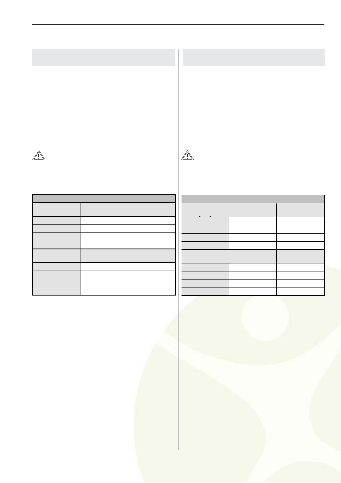
Transportation and storage:
The following storage conditions apply for up to 15 weeks:
te perature: -25 to +70 º C
relative hu idity: 10 - 75 %
air pressure: 500 - 1060 hPa
Storage only in closed or covered spaces; thereafter,
the values of the operating conditions in the operating
instructions apply.
Hinweise zur sicheren Montage
Sehr geehrter Betreiber,
das Wandlager, der Ausleger mit Federarm darf nur
durch eine Fachkraft (Elektriker, Techniker) oder ver-
gleichsweise qualifiziertes Personal montiert werden.
Der 23 V Anschluß darf nur durch einen Elektriker aus-
geführt werden.
Sehr geehrter Monteur,
bitte lesen Sie diese Montageanweisung sehr sorgfältig
und beachten Sie die Sicherheitshinweise und Anforde-
rungen dieser Montageanweisung.
Bei Auftreten besonderer Proble e, die in dieser Mon-
tageanweisung nicht ausführlich genug behandelt werden,
wenden Sie sich zur Ihrer eigenen Sicherheit bitte an Ih-
ren Lieferanten.
Bildzeichenerklärung:
Sicherheitssy bole achen Sie auf sicherheitskritische
Bedienungsfehler auf erksa .
WARNUNG!
bei Nichtbeachtung besteht die Möglichkeit einer schwe-
ren oder sogar tödlichen Verletzung.
VORSICHT!
bei Nichtbeachtung besteht die Möglichkeit von ittle-
ren bis leichten Verletzung oder Sachschäden.
HINWEIS!
gibt Anwendungstips und nützliche Infor ationen.
Transport und Lagerung:
bis 15 Wochen gelten folgende Lagerbedingungen:
Te peratur: -25 bis +70 °C
Relative Feuchte: 10 - 75 %
Luftdruck: 500 - 1060 hPa
Lagerung nur in geschlossenen oder überdachten Räu-
en, danach gelten die Werte der Betriebsbedingungen
in der Gebrauchsanweisung.

Seite / Page 4
150 50 59 / 01 - 2004
DeutschEnglish
1 tatic inspection
NOTE:
The static (structural) inspection must be carried out before the installation
of the wall or ceiling anchorage.
The strength of the construction ust be designed,
checked and certified by a structural engineer.
The respective regional construction regulations that
apply ust be followed.
If a wrong hole is drilled by istake, e.g. drilling of a
reinforce ent rod, the structural engineer who is re-
sponsible ust be contacted, since adequate static
load distribution in the ceiling ay have been endan-
gered.
Declaration of acceptance:
It is hereby certified that the supporting wall/ceiling and
the anchoring of the Acrobat Swing is safe and adequate-
ly strong.
Project: __________________________________
__________________________________
__________________________________
Anchoring (please check the one that is applicable):
- with counter-plate O
- other O
Location: __________________________________
__________________________________
Signature/Stamp (Structural Engineer / Construction
Authority)
1 tatischer Nachweis
HINWEIS:
Der statische Nachweis muß vor der Montage der Wand oder Decken
befestigung erfolgen!
Die Tragfähigkeit der Konstruktion uß von eine Sta-
tiker geplant, überprüft und bestätigt werden.
Die jeweils gültigen regionalen Baubesti ungen
sind zu beachten.
Sollte es zu einer Fehlbohrung ko en, zu Bei-
spiel durch Anbohren eines Bewehrungseisens, so
ist der zuständige Statiker einzuschalten, da die aus-
reichende statische Lastverteilung in der Decke ge-
fährdet sein kann!
Abnahmeerklärung:
Hier it wird bestätigt, daß die tragende Wand / Decke
und die Verankerung des Acroabat Swing sicher und trag-
fähig ist.
Projekt: __________________________________
__________________________________
__________________________________
Verankerung (zutreffendes bitte ankreuzen):
- it Gegenplatte O
- Sonstige O
OR : __________________________________
__________________________________
Unterschrift / Stempel: (Statiker / Baubehörde)

Seite / Page 5
150 50 59 / 01 - 2004
DeutschEnglish
2 election of the fastening agent
The selection of the fastening agent according to table
1, Load data and the safe execution of the fastening
is the responsibility of the person in charge of the in-
stallation
In case of light construction walls, we reco end fa-
stening with a counter-plate (not shipped).
WARNING - Load data:
Please refer to the following table for the load data (rounded up)
of the co plete ceiling odel.
The specified regional safety factors ust be taken into account!
2 Auswahl der Befestigungsmittel
Die Auswahl der Befestigungs ittel nach der Tabelle
1, "Lastdaten" und die sichere Ausführung der Befesti-
gung unterliegt der für die Montage verantwortlichen
Person.
Bei Leichtbauwänden e pfehlen wir die Befestigung
it einer Gegenplatte (nicht i Lieferu fang).
WARNUNG - Lastdaten:
Die Lastdaten (aufgerundet) des Wandgerätes können der nach-
folgenden Tabelle entno en werden.
Die vorgeschriebenen regionalen Sicherheitsfaktoren sind ein-
zurechnen!
Maximale
Auslegerlänge
[]
Maximale Geräte-
last [N] Biegemoment
MB[Nm]
300 210 325
600 150 365
750 130 285
950 100 260
Maximale
Auslegerlänge Senkrechte
Gewichtskraft FG[N] Dübelauszugskraft
FD[N]
300 300 1750
600 260 1950
750 245 1500
950 225 1400
Lastdaten: Wandversion
Maximum extension
arm length [mm] Maximum device
load [N] Bending moment
MB[Nm]
300 210 325
600 150 365
750 130 285
950 100 260
Maximum extension
arm length [mm] Vertical
weight force FG[N] Dowel extraction
force FD[N]
300 300 1750
600 260 1950
750 245 1500
950 225 1400
Load data: Wall model

Seite / Page 6
150 50 59 / 01 - 2004
DeutschEnglish Abbildung / Figure
Figure / Abbildung 1
1 Plastic covers
Kunststoffabdeckteile
2 Holes
Bohrungen
2
1
1
90 300 / 600 /750 / 950
45
60
65
20,5
190
800
65
50
65
1310
H = 2000
2488
45°
50°
3 Wandlager
montieren
HINWEIS:
Für den Netzanschluß des Auslegers ist
eine ordnungsgemäß geerdete Steckdo
se im Bereich des Wandlagers notwen
dig. Die Netzleitung des Auslegers hat eine
Länge von 2 Metern.
1. Zwei Kunststoffabdeckteile
(1) abneh en.
2. Nach Bohrschablone (vorletz-
te Seite) senkrecht anreißen.
3. Zwei Bohrungen nach Anga-
ben des Befestigungs ittel-
herstellers bohren.
4. Befestigungs ittel bündig it
der Wand einsetzen.
HINWEIS:
Die Montage erst nach dem Aushärten des
Bindemittels fortsetzen.
5. Befestigungs ittel in die bei-
den Bohrungen (2) einstek-
ken und Wandlager senk-
recht anschrauben.
HINWEIS:
Mit einem Wandarm Anschlagbegrenzer
(optional) kann der Schwenkbereich des
Auslegers seitlich begrenzt werden.
Die Montage des Wandarm Anschlagbe
grenzer ist im Kapitel 4 beschrieben.
6. Die beiden Kunststoffab-
deckteile (1) aufsetzen und si-
cheren Sitz prüfen.
3 Installing the wall
bearing
NOTE:
For the mains connection of the extension
arm, a properly grounded socket in the
vicinity of the wall bearing is required. The
power supply cable of the extension arm
is 2 meters long.
1. Re ove the two plastic co-
vers (1).
2. Make the vertical arkings
using the drilling te plate on
page 13.
3. Drill two holes according to
the specifications of the faste-
ning agent's anufacturer.
4. Install the fastening agent
flush with the wall.
NOTE:
Do not continue the installation before the
binding agent has hardened completely.
5. Insert the fastening agent into
the two holes (2) and tighten
the wall bearing in a vertical
position.
NOTE:
You can use a stop (optional) to limit the
lateral swiveling range of the extension arm.
The installation of the stop is described in
chapter 4.
6. Install the two plastic covers
(1) and check the for fir
seating.


Seite / Page 8
150 50 59 / 01 - 2004
DeutschEnglish Abbildung / Figure
Figure / Abbildung 3
1
2
3
4
5
6
7
8
5 Ausleger mit Feder-
arm montieren
WARNUNG -
STROMSCHLAG:
Bauseitige Spannungsversorgung
spannungslos schalten, gegen Wie-
dereinschalten sichern.
1. Abdeckhülse (4) vo Zapfen
des Wandlagers (3) abneh-
en.
2. Netzleitung (7) durch die Ver-
kleidung (6) des Wandlagers
(2) führen.
VORSICHT -
SCHÄDEN AM GERÄT:
Wird der Zapfen des Wandlagers (3)
vor der Montage des Auslegers (1)
nicht gefettet, wird die Lagerung zer-
stört.
Den Zapfen des Wandlagers (3)
gleich äßig fetten (Fetttyp: Opti ol-
Optipit).
HINWEIS:
Kontrollieren Sie vor dem Aufschieben des
Auslegers, daß die Laufscheibe Æ 48 mm
(5) montiert ist.
3. Ausleger N (1) auf den Zap-
fen des Wandlagers (3) schie-
ben.
4. Kappe (8) aufdrücken.
5. Sicheren Sitz des Auslegers
N (1) prüfen.
1 Extension arm N
Ausleger N
2 Wall bearing
Wandlager
3 Wall bearing pin
Zapfen des Wandlagers
4 Sleeve
Abdeckhülse
5 Disk Æ 48 mm
Laufscheibe Æ 48 mm
6 Cover
Verkleidung
7 Power supply cable
Netzleitung
8 Cap
Kappe
5 Installing extension
arm with spring arm
WARNING -
ELECTRICAL SHOCK:
Power off the on-site power supply
and protect it fro being switched
on again.
1. Re ove the sleeve (4) fro
the pin of the wall bearing
(3).
2. Route the power supply ca-
ble (7) through the cover (6)
of the wall bearing (2).
CAUTION -
DAMAGE TO THE DEVICE:
If the pin of the wall bearing (3) is not
greased before installing the exten-
sion ar (1), the bearing will be da-
aged.
Grease the pin of the wall bearing (3)
evenly using Opti ol-Optipit grease.
NOTE:
Before sliding on the extension arm, make
sure that the disk Æ 48 mm (5) is installed.
3. Slide the extension arm N (1)
onto the pin of the wall bea-
ring (3).
4. Push on the cap (8).
5. Check the extension arm N
(1) for fir seating.


Seite / Page 10
150 50 59 / 01 - 2004
DeutschEnglish Abbildung / Figure
Figure / Abbildung 5
1 Sleeve
Hülse
2 Recessed head screw
Kreuzschlitzschraube
3 Securing segment
Sicherungssegment
4 Bow / adapter with end device
Bügel /Adapter mit Endgerät
1
2
3
4
6 Endgerät
montieren
6.2 Montage
Abb. 5
WARNUNG -
Verletzungsgefahr:
Bei Einsatz eines falschen Siche-
rungsseg entes kann das Endgerät
aus der Anbindung fallen und schwe-
re Verletzungen verursachen.
Nur Original-Sicherungsseg ente
verwenden.
HINWEIS - axi ales
Endgerätegewicht:
Endgeräte dürfen nicht schwerer als die
montierte Federausstattung sein. Die Fe
derausstattung Ihres ACROBAT 2000 ent
nehmen Sie bitte dem Typenschild.
Federvarianten:
1,0 3,5 kg; 3,5 7,0 kg;
7,0 12,0 kg; 12,0 18,0 kg;
18,0 21,0 kg.
Maximales Endgerätegewicht
bei folgenden Auslegerlängen:
300 mm = 21,0 kg; 600 mm = 15,0 kg;
750 mm = 13,0 kg; 950 mm = 10,0 kg.
1. Endgerät an den Bügel / Ad-
apter (4) ontieren.
2. Bügel / Adapter (4) in die An-
bindung des Federar es füh-
ren, Sicherungssegment (3)
einstecken und Hülse (1)
nach unten schieben.
3. Kreuzschlitzschraube (2) ein-
drehen.
4. Sicheren Sitz des Bügels /
Adapters (4) it Endgerät i
Federar prüfen.
5. Federkraft nach Kapitel 4 ein-
stellen.
6 Installing the
end device
6.2 Installation
Fig. 5
WARNING -
Danger of injury:
If an incorrect securing seg ent is
used, the end device ay ay fall out
of the ounting and cause serious
injury.
Use only original securing seg ents.
NOTE - axi u end
device weight:
End devices must not exceed the weight
of the mounted spring system. For details
about the spring system, please refer to
the nameplate of your ACROBAT 2000.
Spring versions:
1.0 3.5 kg; 3.5 7.0 kg;
7.0 12.0 kg; 12.0 18.0 kg;
18.0 21.0 kg.
Maximum end device weight for
extension arms:
300 mm = 21.0 kg; 600 mm = 15.0 kg;
750 mm = 13.0 kg; 950 mm = 10.0 kg.
1. Install the end device to the
bow / adapter (4).
2. Insert the bow / adapter (4)
into the ounting of the spring
ar , insert the securing seg-
ment (3) and slide the sleeve
(1) down.
3. Install the recessed head
screw (2).
4. Check the bow / adapter (4)
with the end device for fir
seating in the spring ar .
5. Adjust the spring force as
described in chapter 4.

Seite / Page 11
150 50 59 / 01 - 2004
DeutschEnglish Abbildung / Figure
7 Federkraft
einstellen
HINWEIS - axi ale
Zuladung an Federar en:
Federarme sind zum Ausgleich des End
geräte Gewichtes mit unterschiedlichen
Federn ausgestattet. Bleibt der Federarm
mit Endgerät nach dem Einstellen der Fe
derkraft nicht in der eingestellten Position
stehen, müssen die Federn durch einen
Service Techniker gewechselt werden.
Federkraft so einstellen:
daß der Federar it Endgerät
in jeder gewünschten Position
stehen bleibt.
1. An der it der Lupe gekenn-
zeichneten Positionen befin-
den sich eine Bohrung (1).
2. Federarm (2) it Endgerät ca.
10° über die Horizontale stel-
len.
3. Sechskantschlüssel SW5 in
die Bohrung (1) stecken.
Sinkt der Federarm ab, ist die
Federkraft zu gering:
- die Einstellschraube uß
nach links in + Richtung (ge-
gen den Uhrzeigersinn) ge-
dreht werden.
Steigt der Federarm nach oben,
ist die Federkraft zu hoch:
- die Einstellschraube uß
nach rechts in - Richtung (i
Uhrzeigersinn) gedreht wer-
den.
Figure / Abbildung 6
1
Unit
Endgerät
360°
10°
2
1 Hole
Bohrung
2 Spring arm
Federarm
7 Adjusting the
spring force
NOTE - axi u additional
load at spring ar s:
Spring arms are equipped with different
springs to compensate the end device
weight. If the spring arm with the end de
vice cannot come to rest in any desired
position after the spring force has been
adjusted, the springs must be replaced by
a service technician.
To adjust the spring force:
ake sure that the spring ar with
the end device can co e to rest
in any desired position.
1. A hole (1) is located at the
positions arked with the rea-
ding glass.
2. Position the spring arm (2)
with the end device approxi-
ately 10° above horizontal.
3. Insert wrench (width 5) into the
hole (1).
If the spring arm drops, the
spring force is too low:
- rotate the adjust ent screw to
the left (counterclockwise) in
the + direction.
If the spring arm rises, the spring
force is too high:
- rotate the adjust ent screw to
the right (clockwise) in the -
direction.

Electrical data
Rated voltage 120 V 230 V 120 V 230 V
Nominal frequency 60 Hz 50 Hz 60 Hz 50 Hz
Rated current 15 A 16 A 15 A 16 A
Weight in kg
Ceiling anchorage
single (DB 2001)
Ceiling anchorage
double (DB 2002)
Spacer tube
Wall bearing
Exten. arm 300 mm
Exten. arm 600 mm
Exten. arm 750 mm
Exten. arm 950 mm 4.2 kg 4.2 kg
Spring arm
Bow
Ext. arm length
300 mm
600 mm
750 mm
950 mm
The device is not suitable for usage in combustible mixtures of
anesthetic agents with air or in combustible mixtures of anesthetic
agents with oxygen or laughing gas.
Class I
EU conformance
The Acrobat 2000 equipment conforms tothe specifications in the
guideline 93/42/EWG (medical products guideline) and the guideline
89/336/EWG (EMV guideline).
The Acrobat 2000 equipment is only approved for connecting
medical examination lamps, operation lamps and flat-screens with
CE markings. If these end devices are connected tothe ACROBAT
2000 equipment, the person operating the equipment must submit a
declaration as per article 12 of the guideline 93/42/EWG (medical
products guideline). A new conformance evaluation is to be carried
out for other end devices.
Extension arms otherthan ONDAL types 77, 77-1, 79 and 2000
must not be installed.
The maximum load must not be exceeded for ACROBAT 2000
equipment:
Ceiling model Wall model
10.6 kg ---
13.9 kg ---
6.78 kg / m---
--- 1.8 kg
3.2 kg 3.2 kg
6.2 kg 6.2 kg
Certifications
VDE, UL, CE
5.0 kg 5.0 kg
Classification according to EN 60601-1
Device of protection class I
Suitable for continuous operation
EU conformance
The product conforms tothe specifications in the guideline
93/42/EWG (medical products guideline) and the guideline
89/336/EWG (EMV guideline).
Classification according to guideline 93/42/EWG, appendix IX
---
2.6 kg 1.3 kg
2.6 kg
---
21.0 kg
18.0 kg
15.0 kg
21.0 kg
15.0 kg
13.0 kg
10.0 kg
Ceiling model Wall model
Elektrische Daten
Nennspannung 120 V 230 V 120 V 230 V
Nennfrequenz 60 Hz 50 Hz 60 Hz 50 Hz
Nennstrom 15 A 16 A 15 A 16 A
Gewicht in kg
Deckenbefestigung
einteilig (DB 2001)
Deckenbefestigung
zweiteilig (DB 2002)
Deckenrohr
Wandlager
Ausleger 300 mm
Ausleger 600 mm
Ausleger 750 mm
Ausleger 950 mm 4,2 kg 4,2 kg
Federarm
Bügel
Auslegerlänge:
300 mm
600 mm
750 mm
950 mm
Deckengerät Wandgerät
---
21,0 kg
18,0 kg
15,0 kg
21,0 kg
15,0 kg
13,0 kg
10,0 kg
--- 1,3 kg
2,6 kg2,6 kg
Gerät ist nicht zur Verwendung in brennbaren Gemischen von
Anästhesiemitteln mit Luft oder in brennbaren Gemischen von
Anästhesiemitteln mit Sauerstoff oder Lachgas geeignet.
Klasse I
EG-Konformität
Die Acrobat 2000 Geräte stimmen mit den Vorschriften der
Richtlinie 93/42/EWG (Medizinprodukterichtlinie) und der Richtlinie
89/336/EWG (EMV-Richtlinie) überein.
Die Acrobat 2000 Geräte sind nur für den Anschluß medizinischer
Untersuchungsleuchten, Operationsleuchten und Flachbildschirmen
mit CE-Kennzeichung zugelassen. Beim Anbinden dieser
Endgeräte an die ACROBAT 2000 Geräte, muß der Inverkehrbringer
eine Erklärung nach Artikel 12 der Richtlinie 93/42/EWG (Medizin-
produkterichtlinie) abgeben. Bei der Anbindung von anderen
Endgeräten ist eine erneute Konformitätsbewertung zu erstellen.
Es dürfen nur die ONDAL Ausleger der Typen 77, 77-1, 79 und
2000 montiert werden.
Die ACROBAT 2000 Geräte dürfen nicht über die folgenden
Maximallasten belastet werden:
Deckengerät Wandgerät
10,6 kg ---
13,9 kg ---
6,78 kg / m---
--- 1,8 kg
3,2 kg 3,2 kg
6,2 kg 6,2 kg
Zertifizierungen
VDE, UL, CE
5,0 kg 5,0 kg
Klassifikation nach EN 60601-1
Gerät der Schutzklasse I
Gerät für Dauerbetrieb
EG-Konformität
Das Produkt stimmt mit den Vorschriften der Richtlinie 93/42/EWG
(Medizinprodukterichtlinie) und der Richtlinie 89/336/EWG (EMV-
Richtlinie) überein.
Zuordnung nach Richtlinie 93/42/EWG, Anhang IX

Seite / Page 13
150 50 59 / 01 - 2004
190mm
Drilling template for wall bearing
Bohrschablone Wandlager

90 300 / 600 /750 / 950
45
60
65
20,5
190
800
65
50
65
1310
H = 2000
2488
45°
50°
T +49 (0) 1803 500 435 600
F + 49 (0) 3221 122 682 080
Sparkasse Wittmund
IBAN: DE82285500000150001626
BIC/SWIFT: BRLADE21LER
USt-IdNr: DE285943189
PhysioSupplies
Königsborner Straße 26a
39175 Biederitz
Deutschland
www.physiosupplies.de
Table of contents
Other Ondal Medical Equipment manuals