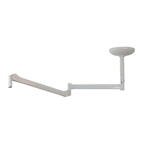
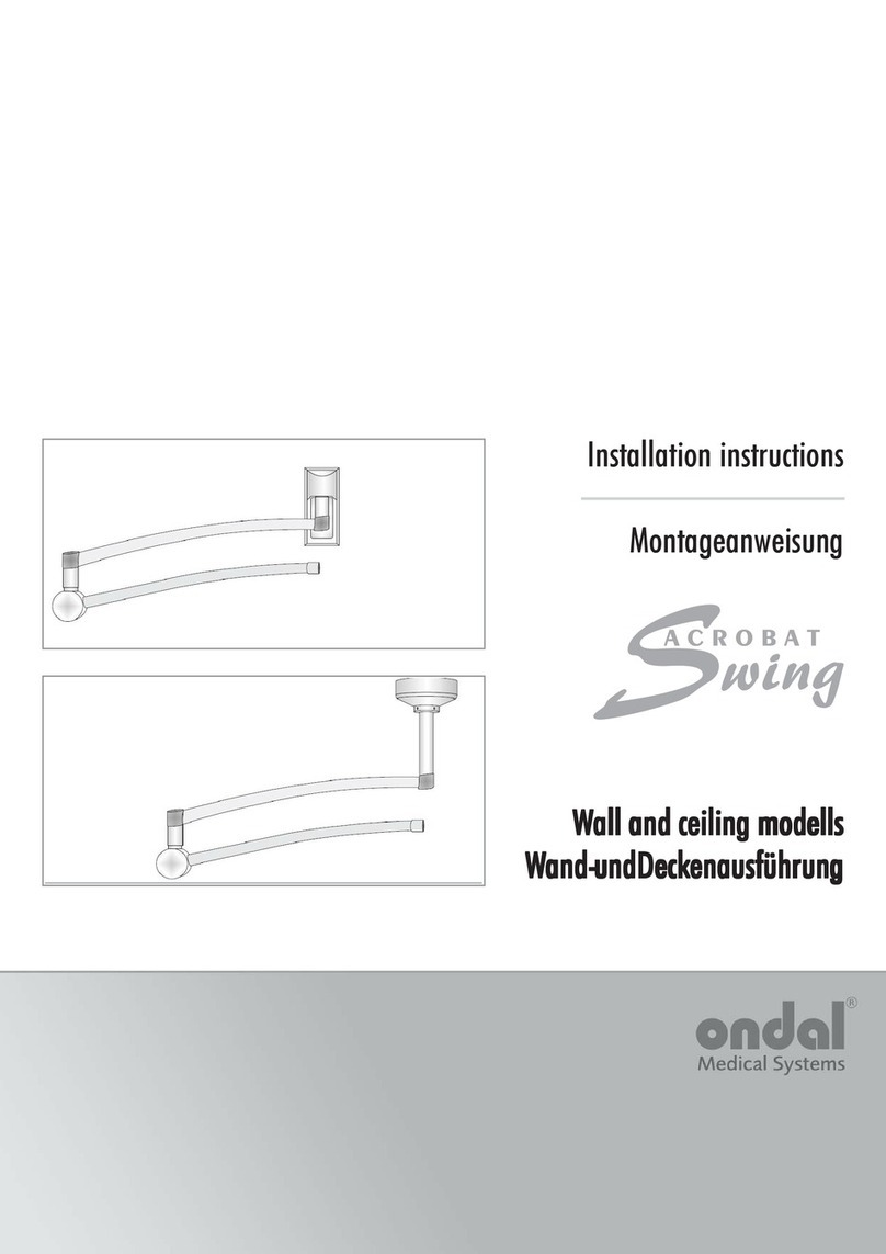
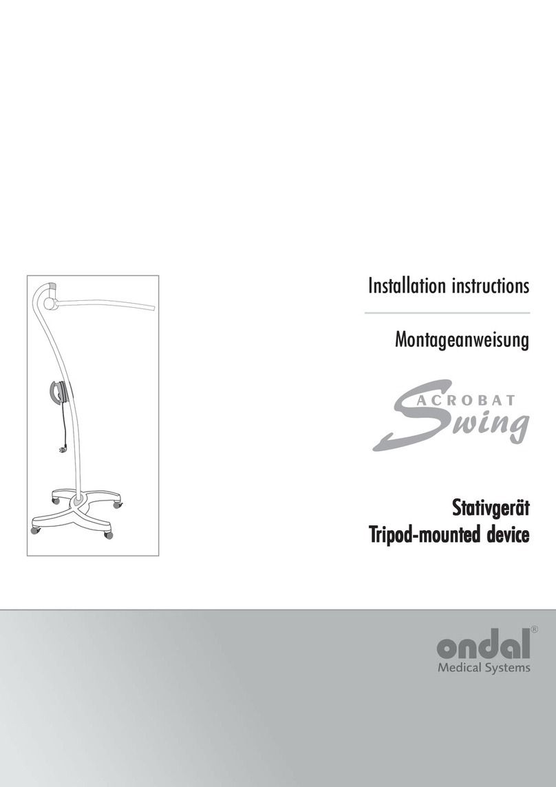
Ondal ACROBAT Swing User manual

Installation instructions
Montageanweisung
StativgerätStativgerät
Stativgerät
TT
TT
Tripod-mounted equipmentripod-mounted equipment
ripod-mounted equipmentripod-mounted equipment
ripod-mounted equipment

Seite / Page 2
38 628 / 03 - 2006
DeutschEnglish
InhaltsverzeichnisInhaltsverzeichnis
Inhaltsverzeichnis SeiteSeite
SeiteSeite
Seite
1 Rollen montieren ............................................... 4
2 Farbfolie aufkleben ............................................ 4
3 Stativrohr montieren ........................................... 5
4 Kunststoff-Halbringe einsetzen .......................... 5
5 Federarm montieren .......................................... 6
6 Endgerät montieren .......................................... 8
7 Federkraft einstellen ........................................ 10
8 Technische Daten ............................................ 11
Packliste Stativfuß
Packstück Nr. 02164
- 1 Stativfuß
Zur Montage geliefertes Zubehör:
- 2 Antistatische Rollen mit Bremsen
- 2 Rollen ohne Bremsen
Packliste Stativrohr und Federarm
Packstück Nr. 02161
- 1 Stativrohr
- 1 Federarm
Zur Montage benötigtes Zubehör:
- 1 Farbfolie
- 2 Kunststoff-Halbringe
- 1 Kunststoffhülse
- 1 Sicherungssegment
- 1 Scheibe
- 1 Sicherungsring
- 1 Sicherungsring-Zange
TT
TT
Table of contentsable of contents
able of contentsable of contents
able of contents PP
PP
Pageage
ageage
age
1 Mounting the rollers ........................................... 4
2 Sticking on the color foil .................................... 4
3 Mounting the tripod tubes.................................. 5
4 Inserting the plastic semi-circular rings ............. 5
5 Installing the spring arm..................................... 6
6 Mounting the end device .................................. 8
7 Setting the spring force ................................... 10
8 Technical data .................................................. 11
Packing list, Tripod base
Packing part no. 02164
- 1 Tripod base
Accessories supplied for assembly:
- 2 anti-static rollers with brakes
- 2 rollers without brakes
Packing list, Tripod tube and spring arm
Packing part no. 02161
- 1 tripod tube
- 1 spring arm
Accessories required for assembly:
- 1 color foil
- 2 plastic semi-circular rings
- 1 plastic sleeve
- 1 securing segment
- 1 disk
- 1 securing ring
- 1 retaining ring - pliers
Copyright ©2006
ONDAL Industrietechnik GmbH
Wellastr. 2-4
36085 Hünfeld / Germany
ONDAL Industrietechnik GmbH
Wellastr. 2-4
36085 Hünfeld / Germany
++49 / 6652 / 81- 600
++49 / 6652 / 81- 392

Seite / Page 3
38 628 / 03 - 2006
DeutschEnglish
Hinweise zur sicheren MontageHinweise zur sicheren Montage
Hinweise zur sicheren Montage
Sehr geehrter Betreiber,
das Gerät darf nur durch einen Krankenhaustechniker
oder vergleichsweise qualifiziertes Personal montiert
werden.
Sehr geehrter Monteur,
Bitte lesen sie diese Montageanweisung sehr sorgfältig
und beachten Sie die Sicherheitshinweise und Anforde-
rungen dieser Montageanweisung.
Beim Auftreten besonderer Probleme, die in dieser Mon-
tageanweisung nicht ausführlich genug behandelt werden,
wenden Sie sich zur Ihrer eigenen Sicherheit bitte an Ih-
ren Lieferanten.
Bildzeichenerklärung:
Sicherheitssymbole machen Sie auf sicherheitskritische
Bedienungsfehler aufmerksam.
WARNUNG!
bei Nichtbeachtung besteht die Möglichkeit einer schwe-
ren oder sogar tödlichen Verletzung.
VORSICHT!
bei Nichtbeachtung besteht die Möglichkeit von mittle-
ren bis leichten Verletzungen oder Sachschäden.
HINWEIS!
gibt Anwendungstips und nützliche Informationen.
Transport und Lagerung:
bis 15 Wochen gelten folgende Lagerbedingungen:
• Temperatur: -25 bis +70°C
• Relative Feuchte: 10 - 75%
• Luftdruck: 500 - 1060hPa
Lagerung nur in geschlossenen oder überdachten Räu-
men, danach gelten die Werte der Betriebsbedingungen
in der Gebrauchsanweisung.
Instructions for safe assemblyInstructions for safe assembly
Instructions for safe assembly
Dear user,
The equipment may only be assembled by a hospital
technician or a comparably qualified person.
Dear installer,
Please read these installation instructions very carefully
and follow the safety instructions and requirements of these
installation instructions.
If there are any peculiar problems that have not been
treated in sufficient detail in these installation instructions,
please contact your supplier for your own safety.
Explanation of pictorial symbols:
There is a number of safety symbols which make you
aware of possible critical operating errors.
WARNING!
Disregarding this instruction can present the danger of a
serious or even fatal injury.
CAUTION!
Disregarding this instruction can present the danger of a
serious or even fatal injury.
IMPORTANT!
Provides usage tips and useful information.
Transportation and storage
The following storage conditions apply for up to 15 weeks:
• temperature: -25 to +70 º C
• relative humidity: 10 - 75 %
• air pressure: 500 - 1060 hPa
Storage only in closed or covered spaces; thereafter,
the values of the operating conditions in the usage in-
structions apply.

Seite / Page 4
38 628 / 03 - 2006
1
2
1
2
3
Figure / Abbildung 1
1 Anti-static rollers with brakes 2x
Antistatische Rollen mit Bremsen 2x
2 Ring cable lug of the PA cable 2X
Ringkabelschuh der PA-Leitung 2x
3 Tripod base
Stativfuß
DeutschEnglish Figure / Abbildung
1 Adhesive foil
Klebefolie
2 Clear protective foil
Klare Schutzfolie
Figure / Abbildung 2
1 Rollen
montieren Abb. 1
WARNUNG -
Statische Aufladung:
Ohne Montage der PA-Leitung
kann es zur statischen Aufla-
dung des Stativgerätes und zur
Ableitung auf Patienten kom-
men.
Die PA-Leitung montieren.
1. Zwei antistatische Rollen
mit Bremsen (1) durch den
Ringkabelschuh der PA-Lei-
tung (2) führen und vollstän-
dig in den Stativfuß (3) stek-
ken.
VORSICHT:
Der Stativfuß ohne Zusatzge-
wicht darf nur für 1-2 kg schwere
Endgeräte verwendet werden.
2. Zwei Rollen ohne Bremsen
vollständig einstecken.
3. Sicheren Sitz der Rollen prü-
fen.
1 Mounting the
rollers Fig. 1
WARNING -
Static charge
If the PA-cable is not installed,
the tripod equipment may get
statically charged and the char-
ge may get transferred to the
patient.
Install the PA-cable.
1. Guide two anti-static rollers
with brakes (1) through the
ring cable lug of the PA ca-
ble (2) and insert completely in
the tripod base (3).
CAUTION:
The tripod base should be used
without additional weight only for
end devices that weigh 1-2 kg.
2. Completely insert the two
rollers without brakes.
3. Check for firm seating of the
rollers.
2 Farbfolie
aufkleben Abb. 2
1. Augenförmige Vertiefung rei-
nigen.
2. Klebefolie (1) abziehen,
Farbfolie in die augenförmige
Vertiefung einlegen und
gleichmäßig andrücken.
3. Klare Schutzfolie (2) abzie-
hen.
2 Sticking on the
color foil Fig. 2
1. Clean eye-shaped recess.
2. Pull out the adhesive foil (1),
place the color foil in the eye-
shaped recess and press it
uniformly.
3. Pull off the clear protective
foil (2).

Seite / Page 5
38 628 / 03 - 2006
2
3
4
1
1
2
3
1 Winged screw
M8 x 40 mm with spring washer
Flügelschraube M8 x 40 mm mit
Federring
2 Tripod tube
Stativrohr
3 Recess in the tube
Aussparung im Rohr
4 Nose of the tripod base
Nase des Stativfußes
DeutschEnglish Figure / Abbildung
Figure / Abbildung 4
1 Plastic semi-circular rings
Kunststoff-Halbringe
2 Tripod base
Stativfuss
3 Cross-slotted screw
Kreuzschlitzschrauben
Figure / Abbildung 3
3 Stativrohr
montieren Abb. 3
VORSICHT-
Schäden am Gerät:
Ohne Einrasten der Nasensi-
cherung und anschließendem
Verschrauben des Stativrohres,
fällt das Stativ um.
Nasensicherung einrasten und
Flügelschraube M8 x 40mm mit
Federring fest anziehen.
1. Flügelschraube mit Feder-
ring (1) aus dem Stativrohr
(2) herausschrauben.
2. Stativrohr (2) so einsetzen,
daß die Aussparung im Rohr
(3) in der Nase des Stativfus-
ses (4) sitzt und nicht mehr
gedreht werden kann.
3. Sicheren Sitz prüfen.
4. Flügelschraube mit Feder-
ring (1) einschrauben und fest
anziehen.
3 Mount tripod
tube Fig. 3
CAUTION-
Damage to the equipment:
If the nose fastening is not in-
serted properly, and then the
tripod tube has not been bol-
ted, the tripod can fall.
Engage the nose fastening and
tighten the wing-bolt M8 x 40
mm with a spring washer.
1. Unscrew the winged screw
with the spring washer (1)
from the tripod tube (2).
2. Insert the tripod tube (2) in
such a way that the recess in
the tube (3) is seated in the
nose of the tripod base (4)
and cannot be rotated any
more.
3. Check for secure seating.
4. Screw in the winged screw
with the spring washer (1)
and tighten it.
4 Kunststoff - Halb-
ringe montieren
Abb. 4
VORSICHT-
Schäden am Gerät:
Ohne eingesetzte Halbringe,
fällt das Stativ um.
Halbringe einsetzen, Ver-
schrauben und sicheren Sitz
prüfen.
1. Kunststoff-Halbringe (1) in
den Stativfuss (2) eindrük-
ken.
2. Kreuzschlitzschrauben (3)
eindrehen und sicheren Sitz
prüfen.
4 Mounting the
plastic semicircular
rings Fig. 4
CAUTION-
Damage to the equipment:
Without the semi-circular rings
inserted, the tripod will tip over.
Insert the semi-circular rings,
screw them and check secure
fitting.
1. Press the plastic semi-circu-
lar rings (1) into the tripod
base (2).
2. Turn in the cross-slotted
screw (3) and check whether
it is tight.

Seite / Page 6
38 628 / 03 - 2006
DeutschEnglish Figure / Abbildung
Figure / Abbildung 5
1 Cover
Deckel
2 Spring arm
Federarm
12
5 Mounting the sp-
ring arm
5.1 Align the spring arm
with the tripod base
Fig. 5
NOTE:
The spring force of the spring arm
and the tripod base are designed
for heavy end-devices weighing
1-3 kg or 1-6 kg.
The weight category of the sp-
ring arm can be seen from the
printed label under the cover (1).
The weighted tripod base can be
recognized from the additional
weight (metal plate) on the under-
side.
CAUTION-
Damage to the equipment:
If the spring arm is installed for
end devices weighing 1-6 kg
with a tripod base without ad-
ditional weight, the tripod can
tip over.
The spring arm for end-devices
weighing 1-6 kg should only be
installed with a weighted tripod
base.
1. Open the cover (1) at the sp-
ring arm (2) and determine
the weight category.
2. Mount the spring arm accor-
ding to the chapter 5.2, „As-
sembly“.
5 Federarm
montieren
5.1 Federarm dem Stativ-
fuß zuordnen
Abb. 5
HINWEIS:
Die Federkraft des Federarmes
und der Stativfuß sind für 1-3 kg
oder 1-6 kg schwere Endgeräte
ausgelegt.
Die Gewichtkategorie des Feder-
armes entnehmen Sie dem Auf-
druck unter dem Deckel (1).
Der beschwerte Stativfuß ist am
Zusatzgewicht (Metallplatte) an
der Unterseite erkennbar.
VORSICHT-
Schäden am Gerät:
Wird der Federarm für 1-6 kg
schwere Endgeräte mit einen
Stativfuß ohne Zusatzgewicht
montiert, kann das Stativ um-
fallen.
Der Federarm für 1-6 kg schwe-
re Endgeräte darf nur mit ei-
nem beschwerten Stativfuß
montiert werden.
1. Deckel (1) am Federarm (2)
öffnen und Gewichtskatego-
rie feststellen.
2. Federarm gemäß Kapitel 5.2,
"Montage" montieren.

Seite / Page 7
38 628 / 03 - 2006
DeutschEnglish Figure / Abbildung
Figure / Abbildung 6
1 Cross-slotted screw
Kreuzschlitzschraube
2 Cover
Abdeckkappe
3 Spring arm pin
Federarmzapfen
4 Disk
Scheibe
5 Retaining ring
Sicherungsring
6 Plug-socket joint
Steckverbindung
2
1
3
4
5
6
6
5 Mounting the sp-
ring arm
5.2 Assembly
Fig. 6
1. Unscrew the cross-slotted
screw (1), pull the cover (2)
forward and move it upward
to take it out.
CAUTION-
Damage to the equipment:
Without the disk installed, the
retaining ring gets loosened
and the spring arm falls out of
the joint.
Always install the disk.
CAUTION-
Damage to the equipment:
Lubricant will destroy the plas-
tic spring arm pin (3).
Do not grease the plastic spring
arm pin (3).
2. Insert the spring arm pin (3),
place the disk (4) and secu-
re them with the retaining
ring (5).
3. The retaining ring (5) must fit
into the pin groove. This must
be checked.
4. Make the electrical connec-
tion (6).
5. Put on the cover (2) and screw
it fast with the cross-slotted
screw (1).
5 Federarm
montieren
5.2 Montage
Abb. 6
1. Kreuzschlitzschraube (1)
herausschrauben und Ab-
deckkappe (2) nach vorne
ziehen und nach oben ab-
nehmen.
VORSICHT-
Schäden am Gerät:
Ohne montierte Scheibe wird
der Sicherungsring aufgedreht
und der Federarm fällt aus der
Anbindung.
Immer die Scheibe montieren.
VORSICHT-
Schäden am Gerät:
Schmierfett zerstört den Feder-
armzapfen (3) aus Kunststoff.
Den Federarmzapfen (3) aus
Kunststoff nicht fetten.
2. Federarmzapfen (3) einstek-
ken, Scheibe (4) auflegen
und mit dem Sicherungsring
(5) sichern.
3. Der Sicherungsring (5) muß
in die Zapfennut einrasten.
Dies ist zu überprüfen.
4. Elektrische Steckverbindung
(6) herstellen.
5. Abdeckkappe (2) aufsetzen
und mit der Kreuzschlitz-
schraube (1) verschrauben.

Seite / Page 8
38 628 / 03 - 2006
DeutschEnglish Figure / Abbildung
Figure / Abbildung 7
1 Black rubber ring
Schwarzen Gummiring
2 Sleeve
Hülse
3 Slot
Schlitze
4 End device
Endgerät
5 Retaining segment
Sicherungssegment
6 Groove
Nut
7 Locking plate
Verriegelungslasche
1
2
5
3
64
180°
7
m
>
10°
6 Endgerät
montieren
6.1 Variante für Endgeräte
mit 1-3kg Gewicht Abb. 7
HINWEIS:
Das Endgerät darf nicht mehr als
3 kg wiegen.
1. Netzstecker ziehen und gegen
Wiedereinstecken sichern.
2. Schutzkappe aus der Feder-
armöffnung nehmen.
3. Schwarzen Gummiring (1)
auf sicheren Sitz prüfen, die-
ser muß fest hinter den 4 Nop-
pen in der Hülse (2) sitzen.
4. Kunststoffhülse (2) so auf
den Federarm schieben, daß
die beiden Schlitze (3) zur
Deckung kommen.
WARNUNG -
Verletzungsgefahr:
Der nach unten gedrückte Fe-
derarm kann hochschnellen
und zu Verletzungen führen.
Während der Montage des End-
gerätes dürfen sich keine Per-
sonen im Schwenkbereich des
Federarmes aufhalten.
5. Endgerät (4) einschieben und
Sicherungssegment (5) voll-
ständig in den Schlitz (3) ein-
stecken, so daß das Siche-
rungssegment in der Nut (6)
geführt wird.
6. Hülse (2) um 180- Grad drehen,
bis ein hörbares Klicken erfolgt.
7. Sicheren Sitz des Endgerä-
tes (4) prüfen.
VORSICHT-
Schäden am Gerät:
Nach der Montage des Endge-
rätes Kipptest gemäß DIN EN
60601-1 durchführen.
6 Mounting the
end-device
6.1 Variant for end devices
with 1-3kg weight Fig. 7
NOTE:
The end-device should not weigh
more than 3 kg.
1. Pull out the mains plug and
secure it from being inserted
again.
2. Take out the protective cover
from the spring arm opening.
3. Check the black rubber ring
(1) for secure seating, it must
be seated firmly behind the 4
knobs in the sleeve (2).
4. Push the plastic sleeve (2)
onto the spring arm in such a
way that the two slots (3) are
covered.
WARNING-
Danger of injury:
The spring arm, pressed down-
ward, can jump upward and cau-
se injury. During the installati-
on of the end-device, nobody
should be present within swive-
ling range of the spring arm.
5. Push in the end-device (4)
and the retaining segment
(5) completely in the slot (3),
so that the retaining segment
is guided in the groove (6).
6. Rotate the sleeve (2) through
180 degrees, till there is an
audible click.
7. Check the firm seating of the
end-device (4).
CAUTION-
Damage to the equipment:
After the end-device has been in-
stalled, perform tilt test in accor-
dance with DIN EN 60601-1.

Seite / Page 9
38 628 / 03 - 2006
DeutschEnglish Figure / Abbildung
Figure / Abbildung 8
1 Plastic sleeve
Kunststoffhülse
2 Slot
Schlitze
3 End-device
Endgerät
4 Securing segment
Sicherungssegment
5 Groove
Nut
6 Brake screw
Bremsschraube
1
4
2
3
6
180°
5
m
>
10°
6 Mounting the
end-device
6.2 Variant for end-devices
with 1-6kg weight Fig. 8
(spring arm with brake screw only)
NOTE:
The end-device should not weigh
more than 6 kg.
1. Pull out the plug and secure
it from being inserted again.
2. Take out the protective cover
from the spring arm opening.
3. Push the plastic sleeve (1) on
the spring arm in such a way
that the slots (2) get cover-
ed.
WARNINIG -
Danger of injury:
The spring arm, which is pres-
sed downwards, can jump back-
wards and result in injuries.
During the installation of the
end-device, nobody should be
present within swiveling range
of the spring arm.
4. Push in the end-device (3)
and the securing segment (4)
completely into the slots (2),
so that the securing segment
is guided in the groove (5).
5. Rotate the plastic sleeve (1)
through 180 degrees and turn
in the brake screw (5) till the
end-device (3) is braked.
6. Check the secure seating of
the end-device (3).
CAUTION-
Damage to the equipment:
After the end-device has been in-
stalled, perform tilt test in accor-
dance with DIN EN 60601-1.
6 Endgerät
montieren
6.2 Variante für Endgeräte
mit 1-6kg Gewicht Abb. 8
(nur Federarm mit Bremsschraube)
HINWEIS:
Das Endgerät darf nicht mehr als
6 kg wiegen.
1. Netzstecker ziehen und gegen
Wiedereinstecken sichern.
2. Schutzkappe aus der Feder-
armöffnung nehmen.
3. Kunststoffhülse (1) so auf
den Federarm schieben, daß
die Schlitze (2) zur Deckung
kommen.
WARNUNG -
Verletzungsgefahr:
Der nach unten gedrückte Fe-
derarm kann hochschnellen
und zu Verletzungen führen.
Während der Montage des End-
gerätes dürfen sich keine Per-
sonen im Schwenkbereich des
Federarmes aufhalten.
4. Endgerät (3) einschieben und
Sicherungssegment (4) voll-
ständig in den Schlitz (2) ein-
stecken, so daß das Siche-
rungssegment in der Nut (5)
geführt wird.
5. Kunststoffhülse (1) um 180-
Grad drehen und Brems-
schraube (5) solange eindre-
hen bis das Endgerät (3) ge-
bremst wird.
6. Sicheren Sitz des Endgerä-
tes (3) prüfen.
VORSICHT-
Schäden am Gerät:
Nach der Montage des Endge-
rätes Kipptest gemäß DIN EN
60601-1 durchführen.

Seite / Page 10
38 628 / 03 - 2006
~20°
1
Figure / Abbildung 9
1 Hole for adjusting the spring force
Bohrung zur Federkrafteinstellung
DeutschEnglish Figure / Abbildung
7 Adjusting the sp-
ring force Fig.9
Adjust the spring force such
that:
The spring arm with the end-de-
vice comes to a standstill in any
desired position.
1. Pull the end-device about
20º downwards till the hole (1)
points upward and a screw is
visible under the hole (1).
2. Insert the slotted-screw scre-
wdriver in the hole (1).
If the spring arm drops, the sp-
ring force is too low:
- the setting screw must be ro-
tated to the right (clockwise).
If the spring arm goes upward,
the spring force is too high:
- the setting screw must be ro-
tated to the left (counter-clo-
ckwise).
7 Federkraft
einstellen Abb. 9
Federkraft so einstellen:
daß der Federarm mit Endgerät
in jeder gewünschten Position
stehen bleibt.
1. Endgerät ca. 20° nach unten
ziehen bis die Bohrung (1)
oben steht und unter der Boh-
rung (1) eine Schraube sicht-
bar ist.
2. Schlitzschraubendreher in die
Bohrung (1) stecken.
Sinkt der Federarm ab -
ist die Federkraft zu gering:
- die Einstellschraube muß
nach rechts (im Uhrzeiger-
sinn) gedreht werden.
Steigt der Federarm nach oben-
ist die Federkraft zu hoch:
- die Einstellschraube muß
nach links (gegen den Uhr-
zeigersinn) gedreht werden.

Seite / Page 11
38 628 / 03 - 2006
DeutschEnglish
8 Technische Daten8 Technical data
Elektrische Daten Deckengerät Wandgerät Stativgerät
Nennspannung
je nach Ausführung
120 V / 230 V 120 V / 230 V 120 V / 230 V
Maximale Leistungs-
abgabe bei 120 V
Version
80 W 80 W 80 W
Maximale Leistungs-
abgabe bei 230 V
Version
50 W oder
80 W
80 W 50 W oder
80 W
Nennfrequenz 50 / 60 Hz 50 / 60 Hz 50 / 60 Hz
Ausgangsstrom
bei 12 V *
bis zu 8,75 A bis zu 8,75 A bis zu 8,75 A
Ausgangsstrom
bei 24 V *
bis zu 4,4 A bis zu 4,4 A bis zu 4,4 A
Ausgangsstrom
bei 230 V *
bis zu 10 A bis zu 10 A bis zu 10 A
Gewicht in kg Deckengerät Wandgerät Stativgerät
Federarm 1,431 kg 1,431 kg 1,431 kg
Ausleger 1,630 kg 1,630 kg ---
Deckenbefestigung 2,5 - 5,1 kg --- ---
Wandlager --- 1,8 kg ---
Stativ 3,5 kg
Stativfuß 6,5 kg
Stativfuß
(beschwert)
12,0 kg
Klassifikation nach EN 60601-1
Gerät der Schutzklasse I
Gerät ist nicht zur Verwendung in brennbaren Gemischen von
Anästhesiemitteln mit Luft oder in brennbaren Gemischen von
Anästhesiemitteln mit Sauerstoff oder Lachgas geeignet.
Gerät für Dauerbetrieb
EG-Konformität
Das Produkt stimmt mit den Vorschriften der Richtlinie
93/42/EWG (Medizinprodukterichtlinie) und der Richtlinie
89/336/EWG (EMV-Richtlinie) überein.
Zuordnung nach Richtlinie 93/42/EWG, Anhang IX
Klasse I
EG-Konformität
Zertifizierungen
UL, VDE, CE
Die Acrobat Swing Geräte stimmen mit den Vorschriften der
Richtlinie 93/42/EWG (Medizinprodukterichtlinie) und der Richtlinie
89/336/EWG (EMV-Richtlinie) überein.
Die Acrobat Swing Geräte sind nur für den Anschluß
medizinischer Untersuchungsleuchten, Operationsleuchten und
Flachbildschirmen mit CE-Kennzeichung und max. 6 kg
Eigengewicht vorgesehen. Der Inverkehrbringer muß eine Erklärung
nach Artikel 12 der Richtlinie 93/42/EWG
(Medizinprodukterichtlinie) abgeben.
Bei der Anbindung von anderen Endgeräten ist eine erneute
Konformitätsbewertung zu erstellen.
* je nach Version
Sicherungstyp: T 10 L 250 V
Electrical data Ceiling-unit Wall-unit Stativ-unit
Rated voltage,
depending on model
120 V / 230 V 120 V / 230 V 120 V / 230 V
Maximum power
delivered by the 120
V Version
80 W 80 W 80 W
Maximum power
delivered by the 230
V Version
50 W or
80 W
80 W 50 W or
80 W
Nominal frequency 50 / 60 Hz 50 / 60 Hz 50 / 60 Hz
Output current at
12V *
Up to 8,75 A Up to 8,75 A Up to 8,75 A
Output current at
24V *
Up to 4,4 A Up to 4,4 A Up to 4,4 A
Output current at
230 V *
Up to 10 A Up to 10 A Up to 10 A
Weight in kg Ceiling-unit Wall-unit Stativ-unit
Spring arm 1,431 kg 1,431 kg 1,431 kg
Extension arm 1,630 kg 1,630 kg ---
Ceiling mounting 2,5 - 5,1 kg --- ---
Wall bearing --- 1,8 kg ---
Stativ 3,5 kg
Stativ base 6,5 kg
Stativ base
(weighted)
12,0 kg
Classification according to EN 60601-1
Device of protection class I
Device is not suitable for usage in combustible mixtures of
anaesthetic agents with air or in combustible mixtures of
anaesthetic agents with oxygen or laughing gas.
Device for continous operation
EU-conformance
The product conforms to the specifications in the guideline
guideline 93/42 EWG (guidelines on medical products) and
the guideline 89/336/EWG (EMV guidelines)
Classification according to guidelines 93/42/EWG, appendix IX
Class I
EU-Conformance
Certifications
UL, VDE, CE
The Acrobat Swing equipment conforms to the specifications of the
guideline 93/42/EWG (medical products guideline) and the
guideline 89/336/EWG (EMV guideline).
The Acrobat Swing equipment is only intended for connecting
medical examination lamps, operation lamps and flat-screens with
CE-markings and a maximum of 6 kg. self-weight. The person
operating the equipment must submit a declaration as per article
12 of guideline 93/42/EWG (medical products guidelines).
Another conformance evaluation must be carried out for other end
devices.
* depending on version
Typ of fuses: T 10 L 250 V

ONDAL Industrietechnik GmbH
Wellastr. 2-4
36085 Hünfeld / Germany
Other manuals for ACROBAT Swing
1
Table of contents
Other Ondal Medical Equipment manuals
Popular Medical Equipment manuals by other brands

Getinge
Getinge Arjohuntleigh Nimbus 3 Professional Instructions for use

Mettler Electronics
Mettler Electronics Sonicator 730 Maintenance manual

Pressalit Care
Pressalit Care R1100 Mounting instruction

Denas MS
Denas MS DENAS-T operating manual

bort medical
bort medical ActiveColor quick guide

AccuVein
AccuVein AV400 user manual