•Main Body, LC2-CU 1. Component
Each Part Function
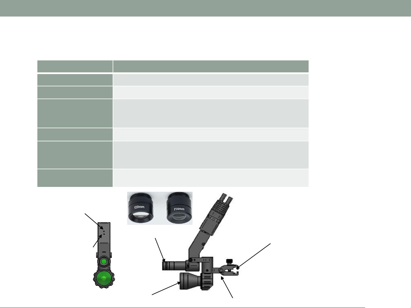
①Initialization
Key
1 second, device will reboot.
than 5 seconds, initialized for factory set up
and SD card will be formatted
port with head assembly unit cable
③Battery status
charged Green on -> Orange on -> Blinking Orange
ON/OFF : Hold the button to downward (1 sec)
switch: Move it upward, all key will not work.
⑤Record button
recording start / stop button
REC LED ON: System initialization completed
REC LED Blinking: Video Recording is in process
REC LED OFF: Ongoing of system initialization or
malfunction
Quick press for one snapshot, Hold for continuous shots
Snapshot Button LED ON:
WiFi On, Possible to connect
viewer
Snapshot Button LED OFF:
WiFi Off, Not possible to
light ON/OFF button, First step can be configured
for remote controller pairing set up
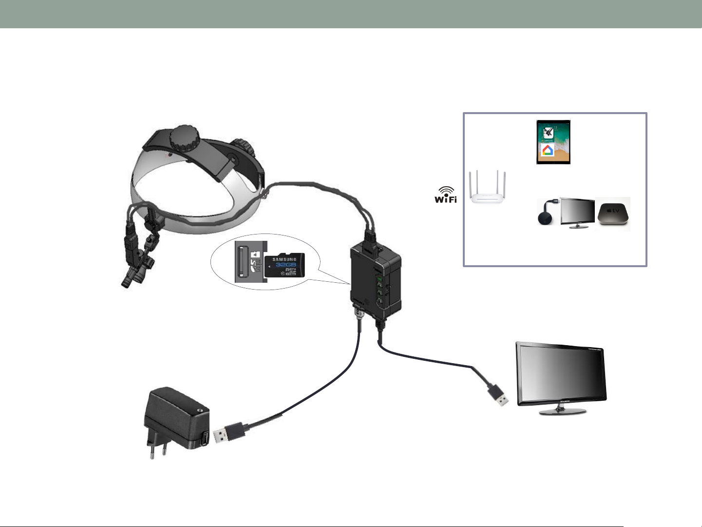
port for recoded video to external device.
GB Micro SDHC Card, More than Class 10, MLC Type
system: FAT32, File allocation size: 32KB
file per 30 minutes (About 2.5 GB)
DC power supply to charge the battery pack
to battery pack charging point
⑬Battery power input
pin
⑫USB slot
⑧Pairing switch
⑪Micro SD card slot
⑩Speaker
⑨Video-Out
④Power switch
⑤Record button
⑥Snapshot button
⑦LED light button
③Battery status LED
①Initialization key
②Camera sensor port
4