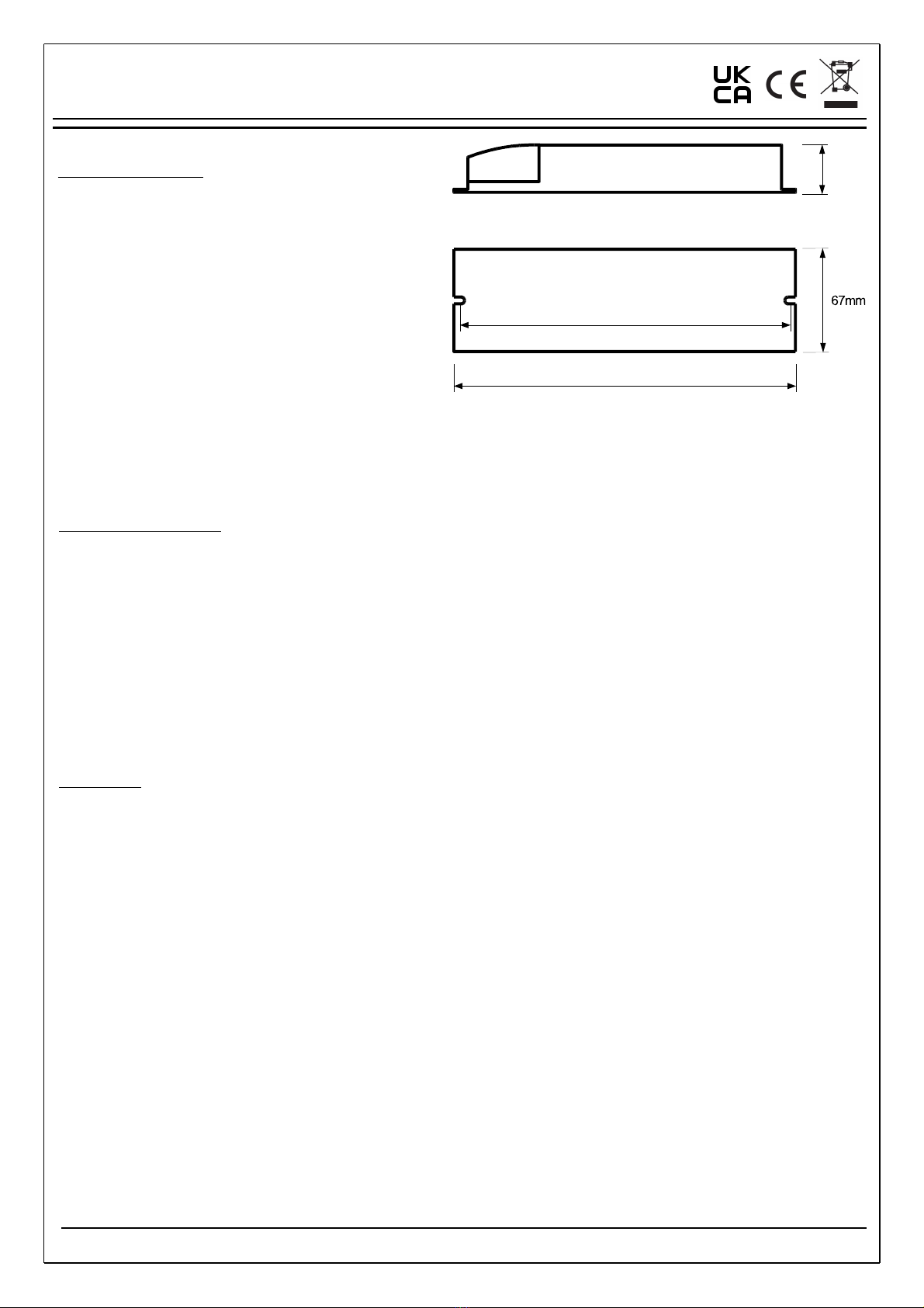
Product Specification
- Product Code (See product label)
- Mains voltage: 230VAC ± 0%
- Mains frequency: 50 - 60Hz
- Power Consumption (Excluding external Driver): 4VA
- Emergency output voltage range: (See product label)
- Emergency Duration: (See product label)
- Battery: (See product label)
- Maximum LED current in maintained mode 2A
- Allowed ambient temp: +5°C to +35°C
- Weight 0.4kg
- Charging time: 24 hours
- Protection class: 2
- Degree of protection: IP20
- Em module complies with: IEC 6 347-2-7
- Suitable for installation to EN50 72 and BS767
Installation & Operating Instructions
Universal Remote Emergency Pack
Installation
NOTE – To comply with regulations, installation must be carried out by
a suitably qualified competent person and in accordance with the
current IEE wiring regulations (BS767 ) and building regulations.
Ensure the mains supply is isolated efore attempting installation!
Page of 2
9939 – Issue
The unit provides reinforced insulation between the mains supply and
battery charging circuit and employs self-resetting protection against
short-circuit of battery terminals. Normal charging will resume
automatically once a fault is removed.
Commissioning:
Once the luminaire has been installed and availability of the un-
switched supply is deemed stable, connect the attery, then
apply mains power to egin the commissioning process.
After applying power, the module will enter commissioning mode
where it will carry out an initial 24 hour charge and a then a full
Duration Test. Once this commissioning test is complete, a further
24 hours will be needed to recharge the battery before normal use.
After successful commissioning, the module should be marked
with the date of commission.
If it is anticipated that the un-switched supply may be interrupted
before normal use, we advise that the battery is left disconnected
and commissioning is delayed until the supply is stable. If mains is
not applied after connecting the battery, the unit will continue to
draw a minimal amount of power from the battery whilst in
standby mode. Continued use in this state in excess of several
months can cause permanent damage to some atteries.
If the remote emergency pack has been stored for a number of
months, it may be necessary to repeat the initial charge/discharge
process several times to re-condition the battery and achieve full
rated emergency duration.
LED Status:
The status of the remote emergency pack can be determined at
any time from the indicator LED. Details of the indicator LED status
conditions in both normal and fault conditions are shown in tables
2 and 3 respectively on page 2.
Automatic Testing:
Once commissioned, the remote emergency pack will establish
randomised delay times to ensure the next scheduled tests do not
coincide with the same test of adjacent remote emergency packs.
(See table on page 2 for details of ‘Test Delay Time’ ranges).
Subsequent routine testing will then take place according to the
‘Test Interval’ times shown in table on page 2.
When a scheduled test is due, the remote emergency pack will
check to see if the lamp is already in use and avoid disruption to
the user for up to 36 hours wherever possible.
To fully reset all test times, disconnect the mains and battery.
Once battery is reconnected and power is restored ,the
commissioning cycle and randomisation process will be re-
initiated. Short discharge periods each month for the Function Test
will not adversely affect One-LUX batteries and should be
considered as a maintenance exercise for the battery. Excessive full
discharge cycles will however adversely affect the design life of the
battery, so excessive testing should be avoided wherever possible.
A full summary of automatic test timings can be seen in table on
page 2
The emergency pack is for use with LED Modules only and can be
supplied in several different wiring formats. Please refer to the
appropriate diagram on page 2 of this leaflet for details of mains supply,
LED driver, battery and lamp connections.
If non-locking external plug and socket connectors are used, i.e. without
means to prevent accidental disconnection, the remote box should be
sited so that it is protected from unauthorised disconnection.
A recessed plastic bezel can be found inside the packaging carton to
assist installation of the indicator LED. A 4- 6mm hole should be drilled
in the required location so it is visible during normal use.
Before use, the battery will need to be connected by plugging in the red
and black lead into the appropriate socket, (See diagrams on page 2).
To avoid subjecting the battery to excessive charge/ discharge cycles
during installation stages, it is strongly recommended the battery is only
connected when the mains supply is stable and the product is ready for
commissioning.
Once all the necessary connections have been made, affix cable clamps
to secure cables in place, place the plastic end cover on and fix with
screws provided to prevent unauthorised access.
Batteries and Disposal
The battery has a designed service life of 4 years and must be replaced
in a timely manner to ensure the integrity of the emergency lighting
system is maintained. In any case, the battery should be replaced
when it no longer provides the rated duration (3 hours).
The manufacturer of the emergency pack is committed to fulfil its
obligations as a producer of batteries used in emergency lighting
applications. End-of-life batteries may either be returned to the
emergency pack manufacturer at the customers cost and
arrangements will be made to ensure their correct disposal.
Alternatively it may be more convenient for the customer to deliver
end-of-life batteries to site(s) of authorized treatment facilities at their
cost and it will be ensured that they are accepted back and
subsequently treated to the standard required by the regulations.