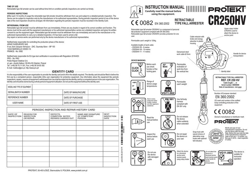
inspection date on the fall arrester, e.g. by using a special label (k).
H. MAXIMUM SHELF-LIFE
The maximum service life of the ST012 plain trolley is unlimited.
CAUTION: The maximum service life depends on the duty and operating environment. Using the device in harsh conditions, with frequent
contact with water, sharp edges, extreme temperatures or exposure to corrosive substances may lead to its withdrawal from
use even after one such instance.
I. DECOMMISSIONING
The device must be taken out of service immediately and disposed of (be permanently destroyed to prevent its accidental use) if
it has arrested a fall, failed to pass a periodic inspection or its reliability raises any concerns.
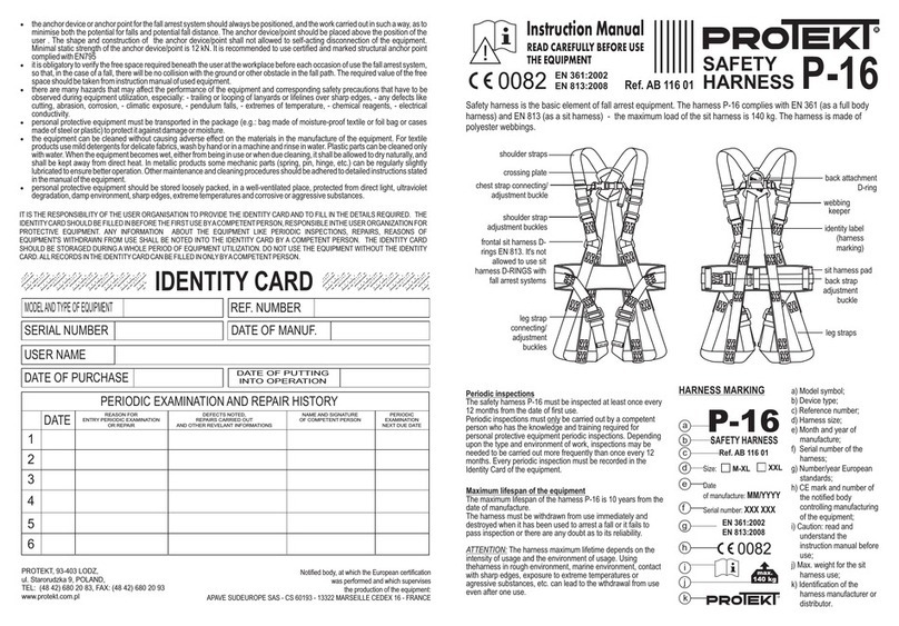
J. MAIN PRINCIPLES OF PERSONAL PROTECTIVE EQUIPMENT (PPE) INTENDED TO PREVENT FALLS FROM A HEIGHT
! PPE shall only be used by personnel trained in its operation.
! PPE shall not be used by individuals with any health condition that may affect their safety during
regular use or in an emergency.
! Prepare an emergency response plan that can be implemented at work when needed.
! While suspended using PPE (e.g. after arresting a fall), mind that there can be injury from suspension.
! To avoid adverse effects of suspension, ensure that an appropriate emergency rescue plan is ready for use. It is recommended
to use support tapes .
! Never attempt to modify the fall arrester without prior written consent from the manufacturer.
! Any repair of the fall arrester shall only be carried out by its manufacturer or its authorised representative.
! PPE shall not be used in any way other than its intended use.
! PPE stands for personal protective equipment and shall be operated by a single dedicated user only.
! Before using the fall arrester, verify that all components of the gear which form the fall arrest system interact correctly.
Periodically inspect the joints and fitting of PPE to avoid accidental release or detachment.
! Do not use PPE kits in which the performance of any component is inhibited by performance of
any other component.
! Before each use of PPE, it is important to carry out a thorough visual inspection in order
to be sure that the device is in good working condition before it is used.
! During the visual inspection before use, check all parts of the equipment, paying particular attention to any
damage, excessive wear, corrosion, abrasions, cuts and malfunctions. Inspect these components with extreme care:
- full body harnesses, waist belts, and positioning belts: shackles, adjustment parts, anchor points (shackles/tethers),
straps, stitching, and loops;
- fall arrest energy absorbers: tether loops, lanyards, stitching, casing, and fasteners;
- textile fibre life lines and anchor lines: lines, loops, thimbles, fasteners, adjustment parts and knots;
- steel cable life lines and anchor lines: cables, cable wires, end clamps, thimbles, fasteners, and adjustment parts;
- cable/lanyard-operated retractable type fall arresters: proper performance of the winding and locking gears, the casing, the shock absorber, and the
fasteners;
- guided type fall arresters: the corpus of the device, correct sliding along the guide, operation of the locking mechanism, rollers,
bolts and rivets, fasteners, energy absorber;
- metal hardware (fasteners, snap hooks, and shackles): load-carrying body, rivet fasteners, main latch, and the locking gear performance.
! At least once a year, every 12 months of operation, PPE requires removal from service for
a thorough periodic inspection. The periodic inspection shall be carried out by a competent, experienced and qualified individual.
The inspection can also be carried out by the equipment manufacturer or its authorised representative.
! In some cases, if the protective equipment has a complex and sophisticated design, such as retractable type fall arresters,
periodic inspections may only be carried out by the PPE manufacturer or his authorised representative. Following the periodic inspection,
the next periodic inspection date shall be identified.
! Regular periodic inspections are critical to the condition of PPE and the safety of its user, which depends on uncompromised performance and durability of
PPE.
! During the periodic inspection, check the legibility of all PPE markings and labels (which apply to the PPE unit in question). Do not use
equipment with illegible marking.
! It is important for your safety that if the equipment is sold outside its country of origin, the supplier of the equipment must
provide the equipment with the user manual, as well as maintenance, periodic inspection and repair information in the language
of the country where the equipment will be used.
! PPE must be taken out of service and disposed of immediately (or other procedures in the user manual should
apply) if it was involved in arresting a fall.
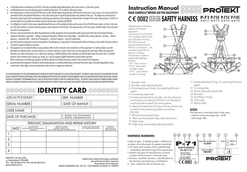
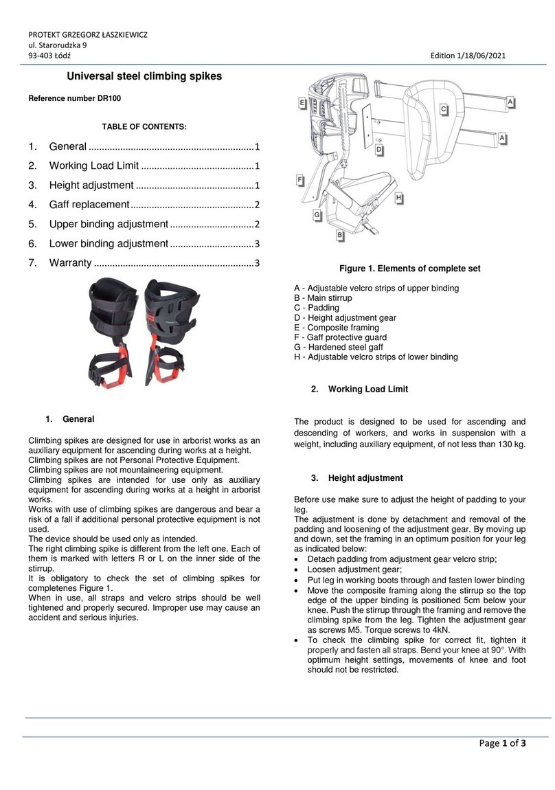
! EN 361 compliant safety full body harnesses are the only acceptable body support equipment for personal protection against falls from a height.
! PPE shall only be connected to the safety full body harness tether points (buckles or loops) marked with an upper-case “A”.
! The anchor point (device) for fall protection equipment should be of stable construction and in a position limiting
the possibility of a fall and minimising the length of a free fall. The equipment anchor point should be located above
the user's working station. The anchor point shape and design shall ensure that PPE is permanently connected and cannot accidentally detach.
The minimum load capacity of the PPE anchor point shall be 12 kN. It is recommended to use
certified, marked and EN 795 compliant equipment anchor points.
! It is compulsory to check the required clearance underneath the workstation where the personal protective equipment will be used
to avoid hitting objects or a lower plane when arresting a fall.
The size of the required clearance under the workstation shall be verified with reference to the user manual of the PPE to be used.
EN – ATTENTION: Read and understand this User Manual before using the device.
A. GENERAL INFORMATION
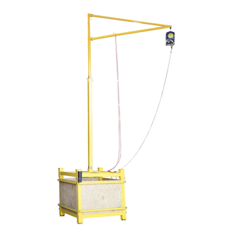
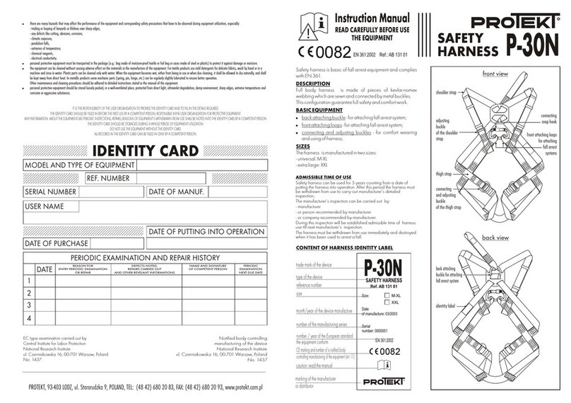
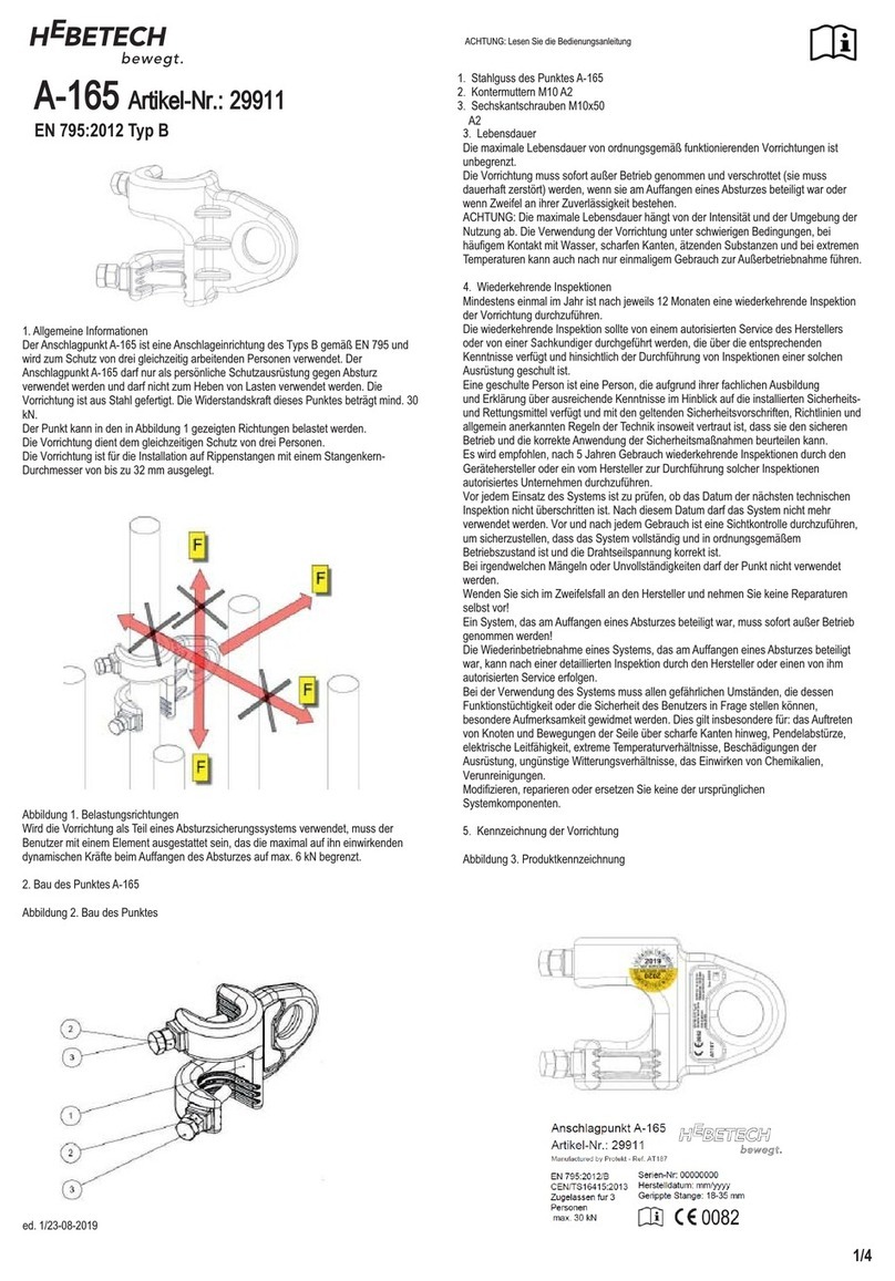
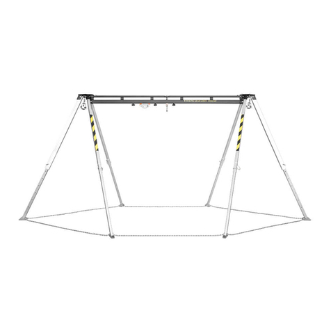
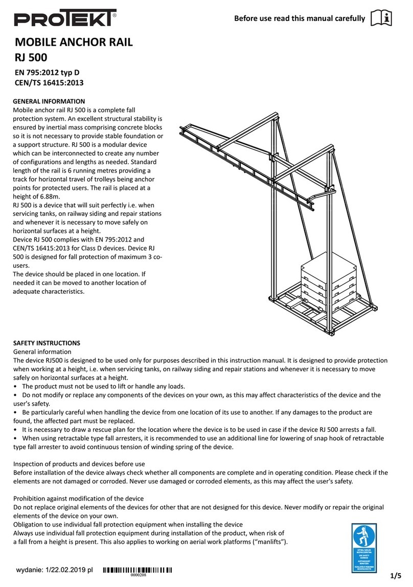
The trolley is a type B anchor device complying with EN 795 and is used to protect two people working at the same time. The anchor point may be
used exclusively as a means of personal protection against falls from a height and must not be used for lifting
loads. The device is made of steel. The strength of this point is min. 13 kN. The device comes in two sizes providing
an adjustable range of 50 to 380 mm.
B. CONSTRUCTION OF THE POINT
1. Trolley body with adjustment sleeve and an anchor point
2. Main device axle in 310 and 500 mm lengths
3. Adjustment sleeve locking device with a safety lanyard
4. Equipment nameplate
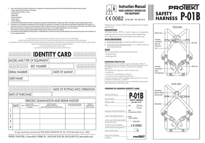
C. LABELLING
(a) device type
(b) model
(c) part number.
(d) serial number
(e) lanyard's production date (month/year)
(f) CE marking and the registration number of the notified body responsible for the device production process control
(g) caution: read the manual before use
(h) number: year of the European standard issue / device type
(i) device for protection of one person
(j) manufacturer's identification
(k) label for marking the date of the next periodic inspection of the device
D. INSTALLATION OF THE TROLLEY
- The plain trolley is designed for installation on steel and aluminium T-section beams with a width of 50 mm to 380 mm and
minimum height of 60 mm capable of supporting loads >13 kN at the installation site. The beam must be fixed
horizontally, above the user - D.1 .
- The anchor must not be used on vertical or inclined beams.
- Special safety devices (stoppers) must be installed on the ends of the beam to prevent the trolley from slipping off the rail - D.2. It is not allowed
to use the trolley on rails without protected ends - D.3.
- The shape and design of the beam must prevent the trolley from detaching on its own. The durability of the installation and the strength of the beam must
be checked and
certified by a qualified technician.
- If the dimension of the structure is within the range of:
- 50 to 200 mm, a (B) axle with a length of 310 mm should be used;
- 200 to 380 mm, a (B) axle with a length of 500 mm should be used.
E. ASSEMBLY OF THE TROLLEY
- Pull the safety cable wheels out of the pin holes, then slide the pins out of the adjustment sleeve holes - E.1
- Connect the two halves of the device with a pre-prepared axle of a length appropriate for the size of the beam structure - E.2
- Secure one half of the trolley at the end of the axle with a pin to prevent it from falling out - E.3
- Connect the two halves of the device with the previously prepared axle by placing the trolley on the profile at the same time. By means of an adjustment
sleeve (with multiple
cross-holes) ensure by rotation and traverse that the lateral play of the trolley on the structure profile is no more than 3 mm - E.4
- Correct adjustment of the play is necessary to ensure that the trolley rides along the structure and does not skew or lock onto the profile
during movement. Sleeves with holes placed spirally around their circumference with a pitch of 4 mm are used for precise clearance of the trolley,
which ensure that the correct clearance is obtained in every case of construction profile widths between 50 and 380 mm - E.5
F. ATTACHMENT OF PROTECTIVE EQUIPMENT AGAINST FALLS FROM A HEIGHT
- If the plain trolley is part of a fall arrest system, the user must be equipped with a device reducing the braking force
that acts on the user during a fall arrest to a maximum of 6 kN.
- Certified connectors complying with EN 362 must be used to attach fall protection equipment to the anchor trolley - F.1.
- Before each use, make sure that the plain trolley is installed in such a way that the minimal distance below the user's feet
(CLR) necessary to safely arrest the fall is maintained so that a collision with the ground or others obstacles does not occur
- F.2. The value of the required free fall distance must comply with the required value given in the user manual of
the fall arrest equipment used.
- During operation, the occurring play in the protective equipment should be reduced to keep the free fall path to a minimum.
- To avoid a pendulum effect during fall arrest, make sure that the deflection of the safety lanyard
from the vertical line of the trolley was not greater than 30o - F.2.
- The maximum load that the plain trolley can transfer to the structure during operation is 13 kN. The load is directed according to
FA direction - F.3.
G. SCHEDULED INSPECTION
At least after every 12 months of operation – starting from the date of first use – a periodic inspection of the fall arrester shall be performed.
The periodic inspection shall be carried out by a competent and qualified individual, experienced in carrying out
periodic PPE inspections.
The operating conditions may affect the frequency of periodic inspection, which can be carried out more frequently than
every 12 months of operation. Each periodic inspection shall be recorded in the fall arrester's service log. It is recommended to display the next periodic
