One Stop Systems Gen2 ExpressBox 16 - Smart User manual

Gen2 ExpressBox 16 - Smart
EB16 Smart Expansion Systems
16 Slot PCI Express® Expansion System User Manual
SKU: EB16-SX8
www.onestopsystems.com

One Stop Systems
ExpressBox 16 Smart | 2
Table of Contents
Preface 5
Advisories 5
Safety Instructions 7
1Introduction 9
1.1 General Specifications 9
1.2 Basic Features 9
1.3 Smart Features 10
1.4 Specifications 10
1.5 EB16 Smart Main Components 11
1.6 Basic Main Components 12
1.7 Pre-Installation 13
1.8 Parts List 13
1.9 Tools Required for Installation 15
2Hardware Installation 16
2.1 Guidelines for Installation 16
2.2 Open Enclosure 17
2.3 Remove Card Holder Assembly 17
2.4 Install PCIe Cards 17
2.5 Install Host Card 20
2.5.1 x8 Interface Card 21
2.5.2 x16 Interface Card 21
2.5.3 Which slot to plug in the host card 22
2.5.4 Host mode Dipswitch Setting 23
2.5.5 Expansion mode Dipswitch Setting 24
2.6 Connect Cables 25
2.6.1 Connecting x16 Cable 25
2.6.2 Connecting x8 Cable 25
2.7 Connect Power Cables 26
2.8 Power ON Expansion chassis 26
2.9 Power ON Computer 28
3Check & Verify Device 28
3.1 Verify Hardware 28
3.2 Software - Verify Installation 29
3.2.1 Windows OS 29
3.2.2 Mac OS 30

One Stop Systems
ExpressBox 16 Smart | 3
3.2.3 Expansion Slot Utility 30
3.2.4 Apple System Profiler 31
3.2.5 Linux 32
3.3 System Should Be Up and Running 32
4Other Technical Information 33
4.1 PCIe slot Power 33
4.2 Redundant Power Supply Option 34
4.3 Interface Cards 35
4.3.1 x16 Interface Card LEDs 35
4.3.2 x16 Card Bandwidth / Lane Settings 36
4.3.3 x8 Interface Card LEDs and Lane Settings 37
4.4 Backplane 38
4.5 Backplane Block Diagram 39
4.6 Backplane FAQs 40
4.7 Backplane Dipswitches 41
4.8 Backplane Power Supply Connectors 43
4.9 Auxiliary Power Cables 44
4.9.1 Aux Cable Installation 44
4.10 Backplane LEDs 46
4.10.1 Power Management Backplane 46
4.10.2 Backplane Power Indicator 46
4.10.3 Activity Indicator 46
4.11 LED Indicators and Configuration Switches 48
4.11.1 Status Front Panel Indicators 48
4.11.2 Fan LEDs 48
4.11.3 Temperature Sensor Alarm LEDs 48
4.12 Power Supply Indicator LEDs 49
4.13 Reset System to Default Parameters 49
4.14 Pressing and holding the “Alarm Reset” button 49
4.15 Flashing the Netburner 50
4.16 Configure Network Setting 54
4.16.1 How to configure your network setting in Windows OS 54
5Express I/O Manager 55
5.1 Web Server and SNMP Features 55
5.2 Web Access and SNMP Configuration 55
5.3 HOME 56
5.4 ADMINISTRATOR 57
5.5 SNMP SETTINGS 57
5.6 ALARM SETTINGS 58
5.7 NETWORK 59

One Stop Systems
ExpressBox 16 Smart | 4
5.8 SLOT MANAGEMENT 60
5.9 REMOTE MANAGEMENT / MANAGE 61
5.10 PCI-E INFO 62
5.11 Partitioning 63
5.11.1 Configuration 1 63
5.11.2 Configuration 2 64
5.11.3 Configuration 3 64
5.12 How to partition the EB16-SMART 65
5.13 Configuration and PCI-E Info profile 66
5.13.1 PCI-E Info profile for Configuration 1 66
5.13.2 PCI-E Info for Configuration 2 66
5.13.3 PCI-E Info for Configuration 3 67
6Chassis Maintenance 68
6.1 Chassis Cleaning 68
6.2 Fan Replacement 70
6.3 Power Supply Replacement 71
7Troubleshooting 73
7.1 Locate the Problem 73
7.1.1 Windows 73
7.1.2 MacOS 73
7.2 Computer Hangs During Start Up 73
7.3 Computer Doesn’t Detect the Expansion System 74
7.4 Add-in PCIe card not recognized 75
7.5 Support for 3rd Party PCIe cards 76
7.5.1 Windows Error Codes 76
7.6 Computer Hangs after Many Card Installed 77
7.7 Nothing Works 77
8How to Get More Help 78
8.1 Contacting Technical Support 78
8.2 Returning Merchandise 78
7.3 Online Support Resources 78
8Appendix A Compliance 79
8.1 FCC 79
8.2 Industry Canada 79
8.3 CE 79
8.4 ISO 9001:2008 79
8.5 RoHS 79
8.6 WEEE 79

One Stop Systems
ExpressBox 16 Smart | 5
Preface
Advisories
Five types of advisories are used throughout this manual to provide helpful information, or to alert you to the potential for hardware damage
or personal injury.
NOTE
Used to amplify or explain a comment related to procedural steps or text.
IMPORTANT
Used to indicate an important piece of information or special “tip” to help you
CAUTION
Used to indicate and prevent the following procedure or step from causing damage to the equipment.
WARNING
Used to indicate and prevent the following step from causing injury.
DANGER or STOP
Used to indicate and prevent the following step from causing serious injury or significant data loss
COMPATIBILITY ISSUE
Used to indicate a known or potential compatibility issue between OSS and non-OSS hardware that may
cause malfunction.

One Stop Systems
ExpressBox 16 Smart | 6
Disclaimer: We have attempted to identify most situations that may pose a danger, warning, or caution condition in this manual. However, OSS
does not claim to have covered all situations that might require the use of a Caution, Warning, or Danger indicator.

One Stop Systems
ExpressBox 16 Smart | 7
Safety Instructions
Always use caution when servicing any electrical component. Before handling the OSS Expansion chassis, read the following instructions and
safety guidelines to prevent damage to the product and to ensure your own personal safety. Refer to the “Advisories” section for advisory
conventions used in this manual, including the distinction between Danger, Warning, Caution, Important, and Note.
Always use caution when handling/operating the computer. Only qualified, experienced, authorized electronics personnel should
access the interior of the computer and expansion chassis per UL and IEC 60950-1
The power supplies produce high voltages and energy hazards, which can cause bodily harm.
Use extreme caution when installing or removing components. Refer to the installation instructions in this manual for precautions
and procedures. If you have any questions, please contact OSS Technical Support.
WARNING
Never modify or remove the radio frequency interference shielding from your workstation or expansion unit. To do so may
cause your installation to produce emissions that could interfere with other electronic equipment in the area of your
system.
When Working Inside a Computer
1. Before taking covers off a computer, perform the following steps:
2. Turn off the computer and any peripheral devices.
3. Disconnect the computer and peripheral power cords from their AC outlets or inlets in order to prevent electric shock or system
board damage.
In addition, take note of these safety guidelines when appropriate:
To help avoid possible damage to systems boards, wait five seconds after turning off the computer before removing a component,
removing a system board, or disconnecting a peripheral device from the computer.
When you disconnect a cable, pull on its connector or on its strain-relief loop, not on the cable itself. Some cables have a connector
with locking tabs. If you are disconnecting this type of cable, press in on the locking tabs before disconnecting the cable. As you pull
connectors apart, keep them evenly aligned to avoid bending any connector pins. Also, before connecting a cable, make sure both
connectors are correctly oriented and aligned.
CAUTION
Do not attempt to service the system yourself except as explained in this manual. Follow installation instructions closely.
Protecting Against Electrostatic Discharge
Electrostatic Discharge (ESD) Warning
Electrostatic Discharge (ESD) is the enemy of semiconductor devices. You should always take precautions to eliminate any
electrostatic charge from your body and clothing before touching any semiconductor device or card by using an
electrostatic wrist strap and/or rubber mat.

One Stop Systems
ExpressBox 16 Smart | 8
Static electricity can harm system boards. Perform service at an ESD workstation and follow proper ESD procedures to reduce the risk of
damage to components. OSS strongly encourages you to follow proper ESD procedures, which can include wrist straps and smocks, when
servicing equipment.
You can also take the following steps to prevent damage from electrostatic discharge (ESD):
When unpacking a static-sensitive component from its shipping carton, do not remove the component’s anti-static packaging
material until you are ready to install the component in a computer. Just before unwrapping the anti-static packaging, be sure you
are at an ESD workstation or are grounded.
When transporting a sensitive component, first place it in an anti-static container or packaging.
Handle all sensitive components at an ESD workstation. If possible, use anti-static floor pads and workbench pads.
Handle components and boards with care. Do not touch the components or contacts on a board. Hold a board by its edges or by its
metal mounting bracket.

One Stop Systems
ExpressBox 16 Smart | 9
1Introduction
1.1 General Specifications
OSS ExpressBox 16 Smart is a 16-Slot PCI Express® Expansion System. The expansion system consists of a PCIe® host interface card, an iPass
cable, a 4U rack-mount chassis containing a 16 Slot backplane and an expansion interface card, a standard or redundant power supply, and high
volume cooling fans. There are two versions available: ExpressBox 16 Basic and ExpressBox 16 Smart.
ExpressBox 16 Basic
ExpressBox 16 Smart
A choice of two backplane configurations:
EB16-BX4: provides (16) x4 PCIe Gen 2 slots
EB16-BX8: provides (2) x16 PCIe Gen 2 slots and (14) x8
PCIe Gen 2 slots.
Backplane provides (2) x16 PCIe Gen 2 slots and (14) x8 PCIe
Gen 2 slots
LED Status Panel
OSS’s Express I/O Manager management tool for SNMP
monitoring and partitioning of the slots among multiple
computers.
EB16 SMART
EB16 BASIC
Sixteen PCIe slots
Sixteen PCIe slots
Card Retainers
Card Retainers
4 Cooling Fans (Replaceable)
Expansion Backplane
Expansion Backplane
2 Power Supply Modules
1 Power Supply Module
1 Expansion Interface Card
Netburner
No Netburner
Two Power Switches (ON the back of the unit)
Single Power Switch
LED Locator & Reset Button
No LED Locator & Reset Button
1 iPass Connector to Host
1iPass Connectors to Host
16 Card slots
16 Card slots
2 Thumb Screws
2 Thumb Screws
Two Front Handles
Two Front Handles
Front Power Button (On & OFF)
Front LED Indicators
No Front LED Indicators
1 Link Cable
1 Link Cable
1 Host Interface Cards
1 Host Interface card
Express IO Manager / WEB GUI
No Express IO Manager / WEB GUI
1.2 Basic Features
Easy “Plug and Play” installation
PCI Express Gen 2 x16 or x8 interconnection
All slots support full-length cards
Status LEDs on backplane indicate active link, speed (Gen 1 or Gen 2), partial or complete lane training
Automatic power-up control by computer
Four hot-swappable cooling fans
Multiple power supply options with auxiliary power connectors to support cards requiring more than 75 Watts
Industrial 4U rack-mount enclosure
Card retainers keep cards in place and are adjustable to fit any size card
Chassis provides superior EMI control, vibration, shock and moisture resistance

One Stop Systems
ExpressBox 16 Smart | 10
1.3 Smart Features
All the features of the BASIC model
o14 slots x8 PCIe and 2 slots x16 PCIe
OSS Express I/O Manager
Constant critical component monitoring
Front panel status LED display
1.4 Specifications
Item
Description
Technology
PCI Express Bus Specification Revision 2.0
PCI Local Bus Specification Revision 2.3
PCI Bridge Architecture Revision 1.2
Backplane
EB16-BX4 - 16 slots x4 PCIe
EB16-BX8 - 14 slots x8 PCIe and 2 slots x16 PCIe
Interface Cards
Low Profile
PCIe x8 Gen 2
Dimensions: 2.70”H x 4.70” L x 0.62”W
Power Consumption: 1.2A @ +3.3V (3.96 watts)
PCIe x16 Gen 2
Dimensions: 2.75” H x 6.95” L x 0.75”W
Power Consumption: 1.5A @ +3.3V (5 watts)
Interconnect Bandwidth
40Gbps (x8 Link)
80Gbps (x16 Link)
Interface Card
Power Consumption
x8 PCIe: 1.2A @ +3.3V (3.96 watts)
x16 PCIe: 1.5A @ +3.3V (5 watts)
Enclosure
4U Rack-mount
19”W x, 7”H x 20”D
Removable/cleanable air filter
34 lbs / 15.5 Kg
System Cooling
(4) 77 CFM Fans - Hot Swappable
Power Supply Options
850 Watt, 1700 Watt or 850 Watt Redundant
100-240 VAC, 47-63 Hz Power Input
12V @ 60Amps
3.3V @ 33 Amps
Environmental
Ambient Temperature 0° to 50° C
Storage Temperature -55° to 125° C
Relative Humidity 0% to 90% non-condensing
MTBF
850W standard power supply - 185,600 hours
1700W dual standard power supply - 106,600 hours
850W redundant power supply - 720,000 hours
Monitoring
ExpressBox 16 Smart only
Express I/O Manager with built-in web server
LED Indicator on front panel
SNMP
Regulatory Compliance
FCC Class A Verified
CE
RoHS Compliant
Supported Operating Systems
Windows
MacOS
Linux
Warranty
30 day money back guarantee
1 year return to factory

One Stop Systems
ExpressBox 16 Smart | 11
1.5 EB16 Smart Main Components
The 3 expansion interface cards are optional. They are ordered separately.

One Stop Systems
ExpressBox 16 Smart | 12
1.6 Basic Main Components

One Stop Systems
ExpressBox 16 Smart | 13
1.7 Pre-Installation
Before using the OSS Expansion chassis, you should perform the following steps:
•Inventory the shipping carton contents for all of the required parts
•Gather all of the necessary tools required for installation
•Read this manual
1.8 Parts List
Item#
Item Name
Qty
1
16 Slot Expansion Chassis
1
2
3-meter shielded iPass (x8 or x16 PCIe)
1
3
Interface cards (x8 or x16 PCIe)
2
4
U.S. Standard 115V Power Cord
1 for Basic model. 2 for Smart model
5
Quick Start Guide
1

One Stop Systems
ExpressBox 16 Smart | 14

One Stop Systems
ExpressBox 16 Smart | 15
1.9 Tools Required for Installation
To complete the installation of the OSS product you will need a Phillips-head screwdriver and ESD wrist strap to prevent electrostatic discharge.

One Stop Systems
ExpressBox 16 Smart | 16
2Hardware Installation
2.1 Guidelines for Installation
The following steps will guide you through the installation of your OSS Expansion System.
CAUTION
Hardware installation shall be performed only by qualified service personnel per UL and IEC 60950-1.
Electrostatic Discharge (ESD) Warning
All add-in cards are susceptible to electrostatic discharge. When moving cards, it is best to carry the cards in anti-static
packaging. If you need to set a circuit card down, be sure to place it inside or on top of an anti-static surface. For more
information, see “Protecting Against Electrostatic Discharge” in the Preface.
WARNING
High voltages are present inside the expansion chassis when the unit’s power cord is plugged into an electrical outlet.
Disconnect the power cord from the AC outlet before removing the enclosure cover. Turning the system power off at the
power on/off switch does not remove power to components. High voltage is still present.
CAUTION
Before touching anything inside the enclosure, move to an ESD station and follow proper ESD procedures. Failure to do so
may result in electrostatic discharge, damaging the computer or its components. For more information, see “Protecting
Against Electrostatic Discharge” in the Preface.

One Stop Systems
ExpressBox 16 Smart | 17
2.2 Open Enclosure
Loosen the 2 thumbscrews that retain the top cover of the chassis and slide the lid towards you as shown below:
2.3 Remove Card Holder Assembly
Remove the screw on the side of the cardholder assembly and lift upwards.
2.4 Install PCIe Cards
Electrostatic Discharge (ESD) Warning
All add-in cards are susceptible to electrostatic discharge. When moving cards, it is best to carry the cards in anti-static
packaging. If you need to set a circuit card down, be sure to place it inside or on top of an anti-static surface. For more
information, see “Protecting Against Electrostatic Discharge” in the Preface.
WARNING
High voltages are present inside the expansion chassis when the unit’s power cord is plugged into an electrical outlet.
Disconnect the power cord from the AC outlet before removing the enclosure cover. Turning the system power off at the
power on/off switch does not remove power to components. High voltage is still present.

One Stop Systems
ExpressBox 16 Smart | 18
CAUTION
Before touching anything inside the enclosure, move to an ESD station and follow proper ESD procedures. Failure to do so
may result in electrostatic discharge, damaging the computer or its components. For more information, see “Protecting
Against Electrostatic Discharge” in the Preface.
CAUTION
Before installing add-in cards, please ensure that the input current rating specified on the AC input label is not exceeded.
All slots support any combination of x1, x4, x8 and x16 PCIe cards. All slots are physically a x16, but any add-in card is supported. Use the card
hold down to secure the card in the slot.
Refer to the labeling on the backplane to determine electrical configuration of each slot. For trouble-shooting purposes, it is recommended to
install a small number of cards and verify installation before installing the maximum number of cards.
The diagrams below represent the speed of PCIe slots that a specific EB16 can support. If you are unsure of which model you have, refer to the
label on the side panel of the chassis.

One Stop Systems
ExpressBox 16 Smart | 19
In model EB16-BX4 all sixteen slots are x4 PCIe Gen 2 as shown this diagram:
Expansion Slot (PCIe
x16)
PCIe GEN2 X4
PCIe GEN2 X4
PCIe GEN2 X4
PCIe GEN2 X4
PCIe GEN2 X4
PCIe GEN2 X4
PCIe GEN2 X4
PCIe GEN2 X4
PCIe GEN2 X4
PCIe GEN2 X4
PCIe GEN2 X4
PCIe GEN2 X4
PCIe GEN2 X4
PCIe GEN2 X4
PCIe GEN2 X4
PCIe GEN2 X4
HOST
SLOT
1
2
3
4
5
6
7
8
9
10
11
12
13
14
15
16
For Model EB16-BX8 and EB16-SX8, a mixture of x8 and x16 PCIe Gen 2 slots are available as shown in this diagram.
Expansion Slot
(PCIe x16)
PCIe GEN2 X8
PCIe GEN2 X8
PCIe GEN2 X16
PCIe GEN2 X8
PCIe GEN2 X8
PCIe GEN2 X16
PCIe GEN2 X8
PCIe GEN2 X8
PCIe GEN2 X8
PCIe GEN2 X8
PCIe GEN2 X8
PCIe GEN2 X8
PCIe GEN2 X8
PCIe GEN2 X8
PCIe GEN2 X8
PCIe GEN2 X8
HOST
SLOT
1
2
3
4
5
6
7
8
9
10
11
12
13
14
15
16
PCIe
Switch
PCIe
Switch
PCIe
Switch
PCIe
Switch

One Stop Systems
ExpressBox 16 Smart | 20
Install the cards following the card manufacturer’s recommendations. Some card manufacturers recommend that you install their software
driver(s) prior to installing the hardware. If this is the case, be sure to install the PCIe device driver before installation of the expansion chassis.
Make sure that all cards are fully seated in their connectors. When correctly seated in its connector, you will notice a firm resistance when you
pull up gently on the card. To keep the cards in place, secure them in the enclosure with their retaining screws (supplied with the OSS
Expansion chassis.
After securing the cards verify that they do not touch each other. Depending on card size and thickness, you may require mechanical card
guides to ensure isolation, such as the case with 2 single full-length PCIe cards. Card guides for this system can be purchased separately from
OSS.
Re-install cardholder assembly and position guides. The plastic guides can be removed and reversed for short cards. Tighten plastic guides with
a screwdriver. Rotate the plastic pieces until their grooves are aligned with the cards. Reinsert the cardholder into the chassis and tighten the
screw.
2.5 Install Host Card
Begin installation by powering down your host computer. Use the procedures for shutting down your operating system and shutting off power
to your system provided in your owner’s manual or system documentation. The host interface card is mounted to a “full-height” bracket as
shown below. For low profile case applications, you may need to change the mounting bracket to the low profile bracket that shipped with your
system. Remove the screws that hold the card to the bracket. Be sure you are using proper ESD procedures when completing this action.
This manual suits for next models
1
Table of contents
Other One Stop Systems Computer Hardware manuals
One Stop Systems
One Stop Systems ExpressBox 3200 User manual

One Stop Systems
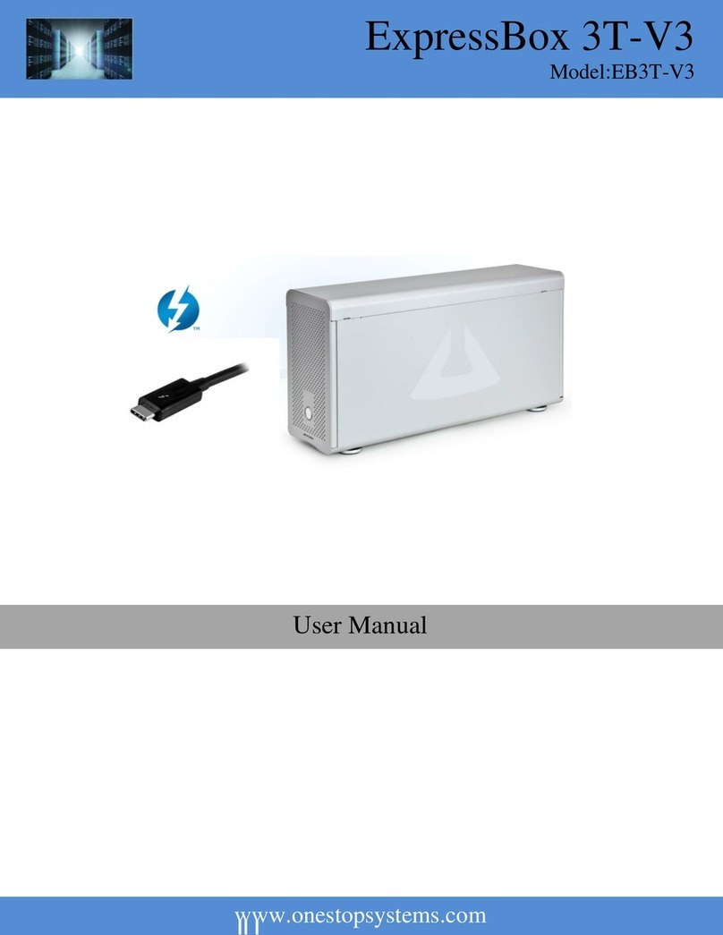
One Stop Systems ExpressBox 3T-V3 User manual

One Stop Systems
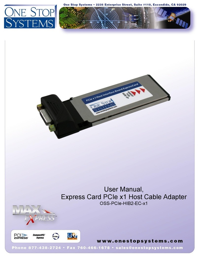
One Stop Systems OSS-PCIe-HIB2-EC-x1 User manual
One Stop Systems
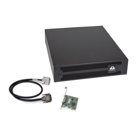
One Stop Systems OSS-PCIe-HIB28-x16-H User manual

One Stop Systems
One Stop Systems OSS-PCIe-HIB38-x8-DUAL User manual

One Stop Systems
One Stop Systems OSS-PCIe-HIB2-EC-x1 User manual

One Stop Systems
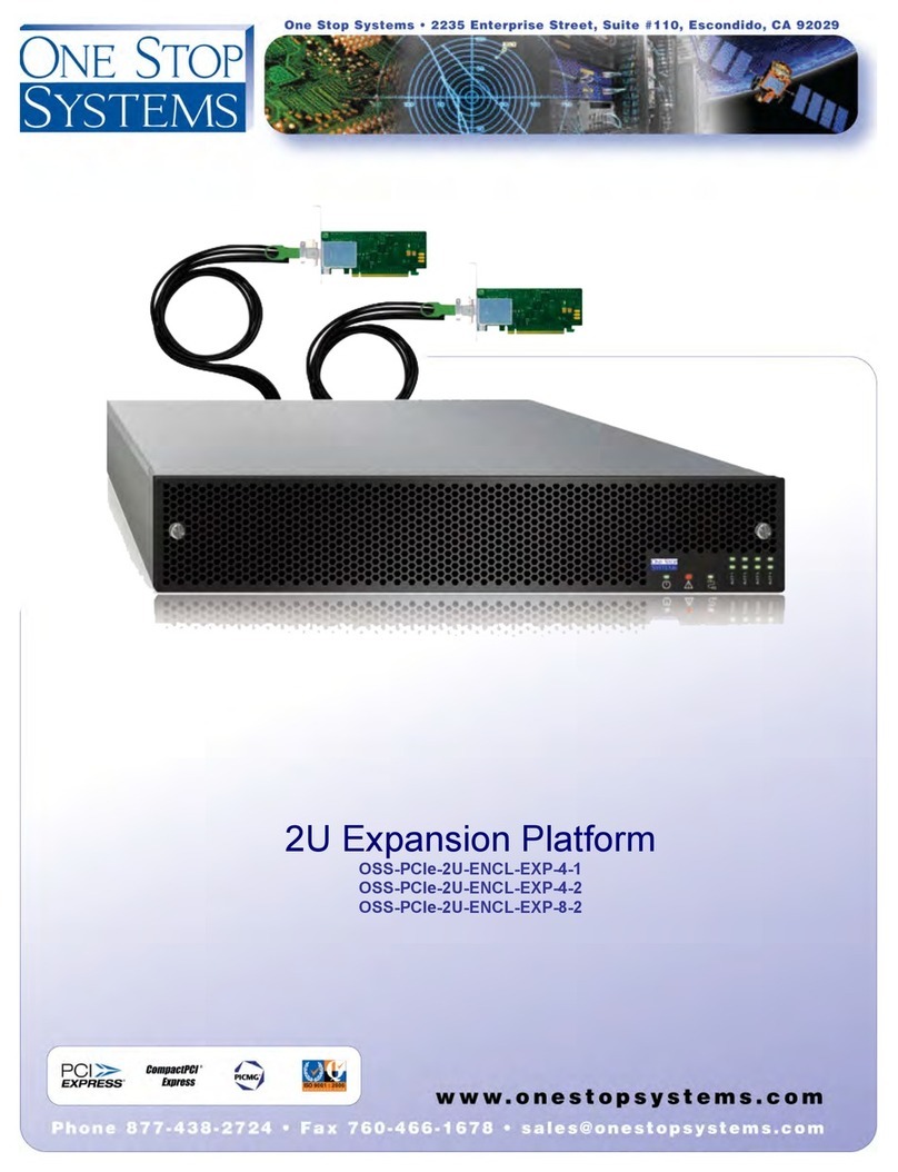
One Stop Systems OSS-PCIe-2U-ENCL-EXP-4-1 User manual

One Stop Systems
One Stop Systems OSS-412-BP User manual

One Stop Systems
One Stop Systems PE3RR User manual
One Stop Systems
One Stop Systems OSS-PCIe-4U-EXP-2022-400 User manual