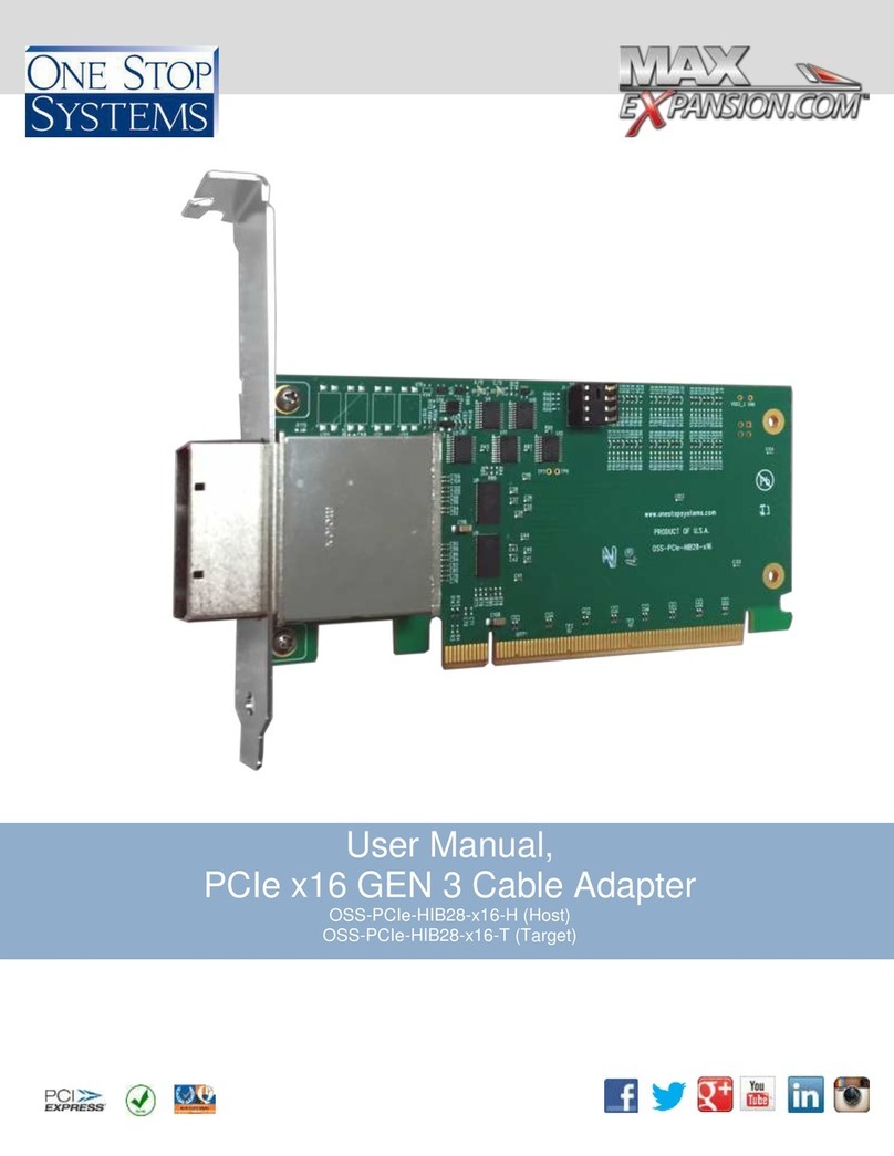
One Stop Systems OSS-PCIe-2U-ENCL-EXP-4-1 User manual

2U Expansion Platform
OSS-PCIe-2U-ENCL-EXP-4-1
OSS-PCIe-2U-ENCL-EXP-4-2
OSS-PCIe-2U-ENCL-EXP-8-2

One Stop Systems 2U Expansion Platform - 2 -
Rev x2
Table of Contents
1 Overview
1.a Introduction..................................................................................................................................... 3
1.b Description .....................................................................................................................................4
1.cUnpacking instructions ................................................................................................................... 4
2 Component Identification
2.a Front panel .....................................................................................................................................5
2.b LED panel identification.................................................................................................................. 5
2.c Rear panel ......................................................................................................................................5
2.d Internal ...........................................................................................................................................6
2.e Base board .....................................................................................................................................6
2.f Riser card ........................................................................................................................................7
2.g System monitor ..............................................................................................................................8
3 Install and Remove I/O Boards
3.a Removing top panel .......................................................................................................................9
3.b Removing connector cables ...........................................................................................................9
3.c Removing tray for I/O board installation .........................................................................................10
3.d Installing I/O boards .......................................................................................................................11
4 Servicing the Enclosure
4.a Removing a fan module .................................................................................................................20
4.b Installing a fan module ...................................................................................................................20
4.c Removing the power supply ...........................................................................................................20
4.d Installing the power supply ............................................................................................................. 21
4.e Cleaning the air filter ......................................................................................................................21
4.f Installing rack slides .......................................................................................................................21
5 Specifications
5.a System monitor ..............................................................................................................................22
5.b Power supply..................................................................................................................................24
5.c Base board .....................................................................................................................................26
5.d Riser boards ...................................................................................................................................27
Appendix A
A.1 System monitor GUI.......................................................................................................................A-1
A.2 Installing the system monitor GUI ..................................................................................................A-1
A.3 Using the system monitor GUI .......................................................................................................A-1
A.4 Configuring sensor parameters...................................................................................................... A-2
A.5 Troubleshooting .............................................................................................................................A-3
Appendix B
B.1 System Monitor Command Protocol ..............................................................................................B-1

One Stop Systems 2U Expansion Platform - 3 -
Rev x2
1 Overview
1.a Introduction
The information contained in this manual may be subject to technical alteration as a result of constant upgrading by
One Stop Systems products. The attached documentation does not entail any guarantee on the part of One Stop
Systems with respect to technical processes described in the manual or any product characteristics set out in the
manual.
One Stop Systems does not accept any liability for any printing errors or other inaccuracies in the manual unless it can
be proven that One Stop Systems is aware of such errors or inaccuracies or that One Stop Systems is unaware of
these as a result of gross negligence and One Stop Systems has failed to eliminate these errors or inaccuracies for this
reason. One Stop Systems expressly informs the user that this manual only contains a general description of technical
processes and instructions, which may not be applicable in every individual case. In cases of doubt, please contact
One Stop Systems.
Note on the Guarantee: Due to their limited service life, parts which by their nature are subject to a particularly high
degree of wear (wearing parts) are excluded from the guarantee beyond that provided by law. This applies, for
example, to batteries.
Exemption from the Guarantee Obligation: One Stop Systems shall be exempted from its guarantee obligations if the
user fails to observe the safety instructions. One Stop Systems can only guarantee the safety, reliability and
performance of the device if all of the safety instructions are observed.
Exclusion of Accident Liability Obligation: One Stop Systems shall be exempted from the statutory accident liability
obligation if the user fails to observe the safety instructions.
Liability Limitation: In the event of damage to the device caused by failure to observe the safety regulations, One Stop
Systems shall not be required to honor the guarantee even during the guarantee period and shall be exempted from
the statutory accident liability obligation.
Safety Instructions
Please read this section carefully and observe the instructions for your own safety and correct use of the device.
Observe the warnings and instructions on the device and in the manual.
One Stop Systems products leave the factory in a perfectly safe condition. In order to maintain this condition and
ensure safe operation, the user must observe the instructions and warnings contained in this manual.
•The device must be used in accordance with the instructions for use.
•The equipment must be installed in accordance with the National Standards and/or Electrical Codes of the
country in question.
•The electrical installations in the room must correspond to the requirements of the respective regulations.
•Take care that there are no cables, particularly mains cables, in areas where persons can trip over them.
•Use only the cable supplied by One Stop Systems.
•Do not set up the device where it is exposed to direct sunlight, in the proximity of heat sources or in a damp
location. Make sure the device has adequate ventilation.
•Only devices and components may be connected to the interfaces of the system, which fulfill the requirements
of a SELV circuit (Safety extra Low Voltage) in accordance with EN60950.
•It must be assumed that safe operation is no longer possible:
oIf the device has visible damage.
oIf the device no longer functions.
•In these cases the device must be shut down and secured against unintentional operation.
•If extensions are made to the device the legal stipulations and the device specifications must be observed.
•Assembly, extensions, new settings, alterations or repairs may be carried out only as authorized by One Stop
Systems.
•Adjustment, maintenance or repair on the open device may be carried out only as authorized by One Stop
Systems.
•Only original accessories approved by One Stop Systems may be used.
•The inside of the enclosure is considered a “Service Access Area.”
Warning! Hazardous voltages exist.

One Stop Systems 2U Expansion Platform - 4 -
Rev x2
1.b Description
The Direct Attached 2U expansion platform provides four or eight PCIe x16 Gen2 slots, two PCIe x16 cable interfaces,
ample cooling, and an 850 watt power supply to support up to four GPU boards or other high speed I/O cards, and a
two PCIe x16 Gen 2 host cable adapters and two PCIe x16 one-meter cable.
Three versions available:
•Version 1 provides 2-slot wide PCIe x16 slots –P/N: OSS-PCIe-2U-ENCL-EXP-4-1
•Version 2 provides 4-slot wide PCIe x16 slots –P/N: OSS-PCIe-2U-ENCL-EXP-4-2
•Version 3 provides 4-slot wide PCIe x16 slots –P/N: OSS-PCIe-2U-ENCL-EXP-8-2
2U Accelerator Enclosure Specifications
Enclosure
•Dimensions: 17”W x 3.5” H x 21”D
•Removable front bezel with air filter
•Front panel LEDs
•One or two rear panel PCIe Gen 2 x16 interface(s)
•4 individually removable fans
PCIe backplane
•Supports up to 8 full length, full height PCIe x16 boards
•Single x16 input to rear of enclosure
Power
•Dual 850W 1U removable power supplies
•V1: +12V @ 70A each
•V2: +5Vsb @ 3A each
System
monitoring/alarming
•Monitors up to 8 temperature sensors
•Monitors up to 4fan tachometers
•Monitors up to 3voltages including standard +12V, +3.3V, +5Vsb
Air filter
•30 ppi open cell polyfoam
Operating environment
•Temperature range:
oOperating: 0°—50°C
oStorage: -40°—85°C
•Humidity range:
oOperating: 10% to 90% relative (non-condensing)
oNon-operating: 5% to 95% relative (non-condensing)
•Altitude range:
oOperating: 0 to 10,000 ft
oStorage: 0 to 50,000 ft
Agency compliance
•FCC Class A
•CE Mark
•UL
1.c Unpacking Instructions
1. If the carton is damaged when you receive it, request that the carrier's agent be present when you unpack and
inspect the equipment.
2. After unpacking, verify that all items listed in the packing list are present.
3. Observe all proper ESD safety procedures.
4. Inspect the equipment for shipping damage.
5. Save all packing material for storage or return shipment of the equipment.
6. For repairs or replacement of equipment damaged during shipment, contact One Stop Systems, Inc. to obtain
a Return Materials Authorization (RMA) number and further shipping instructions.

One Stop Systems 2U Expansion Platform - 5 -
Rev x2
2 Component Identification
2.a Front panel components
2.b LED panel components
Power LED behavior
Amber –Standby power
Green –On
Fault LED behavior
Off –No fault occurring
Solid red –Fault occurring (all fans will run at full speed)
1. Temperatures out of limits
2. Voltages incorrect
3. Fan failure or missing fan(s)
4. Missing riser board
5. Switch chip failure
Link and Slot LED behavior
Off – No link
On – All 16 lanes are active at 5 Gb/s
Blinking short on, short off – some lanes are reduced to 2.5 Gb/s
Blinking long on, short off – all lanes are active at 2.5 Gb/s
Blinking short on, long off – some lanes are reduced to 2.5 Gb/s and some lanes are inactive
NOTE: Version 1 will ONLY illuminate slot 1 and slot 2 LEDs.
2.c Rear panel components
PCIe x16 cable
connector
AC power supply
External system
monitor Ethernet
connector
Removable filter bracket
Ground banana
jack
Thumb screw
LED panel
Thumb screw
Thumb screw
Power LED
Fault LED
Link LED
Slot LEDs
Thumb screw
AC power cord
connector
Removal
handle

One Stop Systems 2U Expansion Platform - 6 -
Rev x2
2.d Internal components
Version 1 - OSS-PCIe-2U-ENCL-EXP-4-1
Version 2 – OSS-PCIe-2U-ENCL-EXP-4-2
Version 3 – OSS-PCIe-2U-ENCL-EXP-8-2
Riser boards
Dual 850-watt
power supplies
System monitor
board
PCIe x16 cable
connector
Individually removable
fan modules
Power supply
backplane
Base board
Temperature
sensors
Temperature
sensors
External temperature
sensor headers x4
Riser boards
Base boards
Removable trays
Removable tray
Divider tray
thumb screws

One Stop Systems 2U Expansion Platform - 7 -
Rev x2
System monitor
data connector
DIP Switch 1
(SW1)
DIP Switch 2
(SW2)
2.e Base board components
2.f Riser card components
Version 1 –OSS-PCIe-2U-ENCL-EXP-4-1
Version 2 – OSS-PCIe-2U-ENCL-EXP-4-2
Version 3 – OSS-PCIe-2U-ENCL-EXP-8-2
PCIe x16 cable
connector
External temperature
sensor headers x4
LED/Fan board
data connector
External System
Monitor Ethernet
connector
Riser board
connector
Internal system
monitor Ethernet
connector
Power
connector
PCIe x16 edge
connector
PCIe x16 edge
connector
PCIe x16 slot
connector
PCIe x16 slot
connector
Switch
PCIe x16 edge
connector
Switch
PCIe x16 slot
connector

One Stop Systems 2U Expansion Platform - 8 -
Rev x2
Base board data
connector
System monitor
Ethernet connector
Programming
header
(factory use only)
Programming
power header
(factory use only)
2.g System monitor components

One Stop Systems 2U Expansion Platform - 9 -
Rev x2
3 Install and Remove I/O Boards
NOTE: The following instructions are for Version 1 only, see page 13 for Versions 2 & 3.
3.a Removing top panel
1. If the unit is operational, power it down and unplug the power cord.
2. Remove the unit from the rack.
3. Remove the top cover by unscrewing the thumb screw on the rear of the unit. A screwdriver may be used if
the screw is too tight. Slide the top cover toward the back and gently lift it from the chassis.
3.b Removing connector cables
4. Remove the power connector from the base board by releasing the clip on connector’s edge.
5. Remove the internal Ethernet connector from the base board.

One Stop Systems 2U Expansion Platform - 10 -
Rev x2
6. Remove the LED/fan board connector from the base board by pushing out on the ejector handles.
7. Remove the system monitor connector from the base board by pushing out on the ejector handles.
3.c Removing tray for I/O board installation
8. Remove two screws from the outer edge of the chassis, two screws from the bottom of the chassis and two
screws from the back of the chassis.
4 screws on
back of chassis
2 screws on
bottom of chassis
4 screws on
edge of chassis

One Stop Systems 2U Expansion Platform - 11 -
Rev x2
9. Gently slide the tray out of the chassis being sure to keep all cables clear of the tray.
10. Loosen the six base board screws to release the board from the tray.
3.d Installing I/O boards
11. Install the I/O board by carefully aligning connectors and pushing the board firmly into place.
NOTE: When installing boards into your system that the standard board brackets will not fit. One Stop can
provide new custom slot covers upon request and after receiving a drawing of the bracket. Contact the Sales
Department, sales@onestopsystems.com.
2 screws
2 screws
2 screws

One Stop Systems 2U Expansion Platform - 12 -
Rev x2
12. Tighten the six base board screws.
13. Reinsert the tray into the chassis lining up tabs on bottom of tray to the corresponding lances on the chassis
ensuring all the cables are out of the way.
14. Tighten the six chassis screws.
15. Plug the power connector into the I/O board.
16. Plug the system monitor cable into the base
board connector.
17. Plug the LED/fan board cable into the base
board connector.
18. Plug the internal system monitor Ethernet
cable into the base board connector.
19. Plug the power cable into the base board
connector.
20. Replace the top cover by aligning it with the coordinating notches on the chassis. Slide the top cover into
place. Tighten the thumb screw on the rear panel.

One Stop Systems 2U Expansion Platform - 13 -
Rev x2
NOTE: The following instructions are for Version 2 & 3 only, please see page 9 for Version 1.
3.a Removing top panel
1. If the unit is operational, power down and unplug the power cord.
2. Remove the unit from rack.
3. Remove the top cover by unscrewing the thumb screw on rear of unit. A screwdriver may be used if the
screw is too tight. Slide the top cover toward back and gently lift it from the chassis.
3.b Removing connector cables
4. From the top tray remove the power connector from the base board by releasing the clip on the connector’s
edge.
5. Remove the base board to base board connector.

One Stop Systems 2U Expansion Platform - 14 -
Rev x2
6. Remove two screws from the outer edge the chassis and two screws from the back of the chassis.
7. Gently slide the upper tray out of the chassis being sure to keep all the cables clear of the tray.
8. Remove the tray divider by lifting from the front edge toward the rear of the chassis. Remove the tray divider
by loosening the two thumb screws. Lift from the front edge toward the rear of the chassis and remove the
tray divider.
2 screws on
back of chassis
2 screws on
edge of chassis

One Stop Systems 2U Expansion Platform - 15 -
Rev x2
9. Remove the power connector from the base board by releasing the clip on the connector’s edge.
10. Remove the internal Ethernet connector from the base board.
11. Remove the base board to base board connector.

One Stop Systems 2U Expansion Platform - 16 -
Rev x2
12. Remove the LED/fan board connector from base board by pushing out on the ejector handles.
13. Remove the system monitor connector from the base board by pushing out on the ejector handles.
3.c Removing tray for I/O board installation
14. Remove two screws from the outer edge of the chassis, two screws from the bottom of the chassis and two
screws from the back of the chassis.
2 screws on
back of chassis
2 screws on
edge of chassis
2 screws on
bottom of chassis

One Stop Systems 2U Expansion Platform - 17 -
Rev x2
15. Gently slide the bottom tray out of chassis being sure to keep all the cables clear of the tray.
16. Loosen the six base board screws to release the board from the tray.
3.d Installing I/O boards
17. Install the I/O board by carefully aligning connectors and pushing the board firmly into place.
NOTE: When installing boards into your system that the standard board brackets will not fit. One Stop can
provide new custom slot covers upon request and after receiving a drawing of the bracket. Contact the Sales
Department, sales@onestopsystems.com.
2 screws
2 screws
2 screws

One Stop Systems 2U Expansion Platform - 18 -
Rev x2
18. Tighten the six base board screws.
19. Reinsert the bottom tray into the chassis lining up tabs on bottom of tray to corresponding lances on the
chassis ensuring all the cables are out of the way.
20. Tighten the six chassis screws.
21. Plug the power connector into the I/O board.
22. Plug the system monitor cable into the base
board connector.
23. Plug the LED/fan board cable into the base
board connector.
24. Plug the base board to base board connector
into the lower base board.
25. Plug the internal system monitor Ethernet cable
into the base board connector.
26. Plug the power cable into the base board
connector.
27. Replace the tray divider.
28. Reinsert the top tray into the chassis lining up tabs on bottom of tray to the corresponding lances on the
chassis ensuring all the cables are out of the way.

One Stop Systems 2U Expansion Platform - 19 -
Rev x2
29. Tighten the four remaining chassis screws.
30. Plug the base board to base board connector into the upper tray.
31. Plug the power connector into the upper tray.
32. Plug the power connectors into the upper tray I/O boards.
33. Replace the top cover by aligning it with the coordinating notches on the chassis. Slide the top panel into
place. Tighten the thumb screw on the rear panel.
2 screws on
back of chassis
2 screws on
edge of chassis

One Stop Systems 2U Expansion Platform - 20 -
Rev x2
4 Servicing the Enclosure
4.a Removing a fan module
1. With the unit powered down and the chassis top removed, locate the fan modules at the front of the unit.
2. Gently lift one fan module by the edges until the unit comes free.
4.b Installing a fan module
1. Tilt connector end of fan module into chassis.
2. Match bracket end of fan module with notches in chassis.
3. Snap into place.
4.c Removing the power supply
1. Power down the unit and unplug the power connector from the rear of the unit.
NOTE: You may perform this operation with the chassis lid on or off the unit.
2. Straighten power supply removal handle.
3. Loosen thumb screw. Screwdriver may be used if too tight.
This manual suits for next models
2
Table of contents
Other One Stop Systems Computer Hardware manuals

One Stop Systems
One Stop Systems OSS-PCIe-HIB2-EC-x1 User manual

One Stop Systems
One Stop Systems OSS-PCIe-HIB2-EC-x1 User manual

One Stop Systems
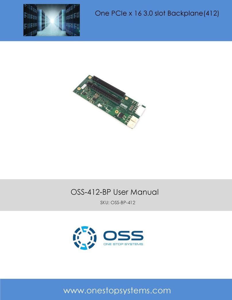
One Stop Systems OSS-412-BP User manual

One Stop Systems
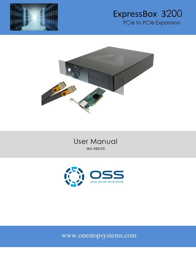
One Stop Systems ExpressBox 3200 User manual

One Stop Systems
One Stop Systems OSS-PCIe-HIB38-x8-DUAL User manual

One Stop Systems
One Stop Systems OSS-PCIe-HIB28-x16-H User manual

One Stop Systems
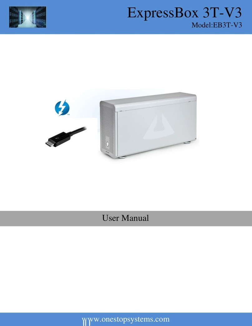
One Stop Systems ExpressBox 3T-V3 User manual

One Stop Systems
One Stop Systems OSS-PCIe-4U-EXP-2022-400 User manual

One Stop Systems
One Stop Systems PE3RR User manual

One Stop Systems
One Stop Systems Gen2 ExpressBox 16 - Smart User manual