OneTouch H800 User manual

M
Mo
od
de
e
l
l H
H8
80
00
0
U
Us
se
er
r'
's
s
M
Ma
an
nu
ua
al
l
FEB-4720 Main Board

Federal Communications Commission (FCC)
This equipment has been tested and found to comply with the limits for a Class A digital device,
pursuant to Part 15 of the FCC Rules. These limits are designed to provide reasonable
protection against harmful interference in a residential installation. This equipment generates,
uses, and can radiate radio frequency energy and, if not installed and used in accordance with
the instructions, may cause harmful interference to radio communications. However, there is no
guarantee that interference will not occur in a particular installation. If this equipment does
cause harmful interference to radio or television reception, which can be determined by turning
the equipment off and on, the user is encouraged to try to correct the interference by one or
more of the following measures:
Reorient or relocate the receiving antenna.
Increase the separation between the equipment and the receiver.
Connect the equipment to an outlet on a circuit different from that to which the receiver is
connected.
Consult the dealer or an experienced radio/TV technician for help.
Shielded interconnect cables and shielded AC power cables must be employed with this
equipment to insure compliance with the pertinent RF emission limits governing this device.
Changes or modifications not expressly approved by the system’s manufacturer could void the
user’s authority to operate the equipment.
Declaration of Conformity
This device complies with part 15 of the FCC Rules. Operation is subject to the following two
conditions:
1. This device may not cause harmful interference
2. this device must accept any interference received, including interference that may cause
undesired operation.
DHHS- the CD-ROM Drive
FDA Regulations require the following statement for all laser-based devices:
“Caution, Use of controls or adjustments or performance of procedures other than those
specified herein may result in hazardous radiation exposure.”
Caution: This appliance contains a laser system and is classified as a “CLASS 1 LASER PRODUCT”.
To use this model properly, read the instruction manual carefully and keep this manual for future
reference. In case of any trouble with this model, please contact your nearest “Authorized Service
Station”. To prevent direct exposure to the laser beam, do not try to open this enclosure.

Important Safety Information
SAFETY INSTRUCTIONS
1. Please read these safety instructions carefully.
2. Keep this User’s Manual for later reference.
3. Disconnect this equipment from the AC outlet before cleaning. Don’t use liquid or spray
detergent for cleaning. Use only a moistened sheet or cloth.
4. For pluggable equipment, the socket-outlet should be installed near the equipment and
should be easily accessible.
5. Keep this equipment from humidity.
6. Lay this equipment on a stable surface when installing.
7. Do not leave this equipment in an non-air-conditioned environment, or in a storage
temperature above 60∘C. Such conditions may damage the equipment.
8. The openings on the enclosure are for air convection and protect the equipment from
overheating. DO NOT COVER THE OPENINGS.
9. Check the voltage of the power source when connecting the equipment to the power outlet.
10. Place the power cord so that it will not be stepped on. Do not place anything over the
power cord. The power cord must be rated for the product and for the voltage and current
marked on the product’s electrical ratings label. The voltage and current rating of the cord
should be greater than the voltage and current rating marked on the product.
11. All cautions and warnings on the equipment should be noted.
12. If the equipment is not used for a long time, disconnect the equipment from the mains to
avoid damage.
13. Never allow liquid into ventilation openings. This could cause fire or electrical shock.
14. Never open the equipment. For safety reasons, qualified service personnel should only
open the equipment.
15. If one of the following situations arises, get the equipment checked by service personnel:
a. The Power cord or plug is damaged.
b. Liquid has penetrated the equipment.
c. The equipment has been exposed to moisture.
d. The equipment does not work well or you cannot get it to work according to the user’s
manual.
e. The Equipment has been dropped and damaged.
f. The equipment has obvious signs of damage.
Caution: Danger of explosion if battery is incorrectly replaced. Replace only with same type, and discard used batteries
according to manufacturers instructions.
Warnings: Not intended for Outdoor Use.

Copyright
The information in this guide is subject to change without prior notice.
The manufacturer shall not be liable for technical or editorial errors or omissions contained
herein, nor for incidental or consequential damages resulting from the furnishing, performance,
or use of this material.
This manual contains information protected by copyright. No part of this manual may be
photocopied or reproduced in any form without prior written consent from the manufacturer.
© 2001 All rights reserved.
The software described in this guide is furnished under a license agreement or nondisclosure
agreement. The software may be used or copied only in accordance with the terms of the
agreement.
Product names mentioned herein may be trademarks and/or registered trademarks of their
respective companies.
First Edition September 2007

T
Ta
ab
bl
le
e
o
of
f
C
Co
on
nt
te
en
nt
t
Chapter
1
2
Chapter 1 2
Introduction 2
Model H800 Characteristics ..................................................................................................2
How to Use This Manual .......................................................................................................3
A Visual Tour of Model H800................................................................................................. 4
What comes with Model H800........................................................................................ 4
Dimensions..................................................................................................................... 6
Connector Panels..................................................................................................................7
Primary Connector Panel ............................................................................................... 7
Secondary Connector Panel........................................................................................... 8
Chapter
2
9
Chapter 2 9
Hardware Setup 9
Model H800 Assembly........................................................................................................... 9
Hard Disk Drive Installation............................................................................................9
Compact Flash Installation........................................................................................... 11
Second LCD Panel Installation..................................................................................... 12
OSD Settings for Second LCD Panel........................................................................... 14
Second LCD with Touch Screen Installation................................................................ 16
Magnetic Card Reader Installation............................................................................... 17
MCR Parameter Modification ....................................................................................... 18
VFD Customer Display Installation............................................................................... 19
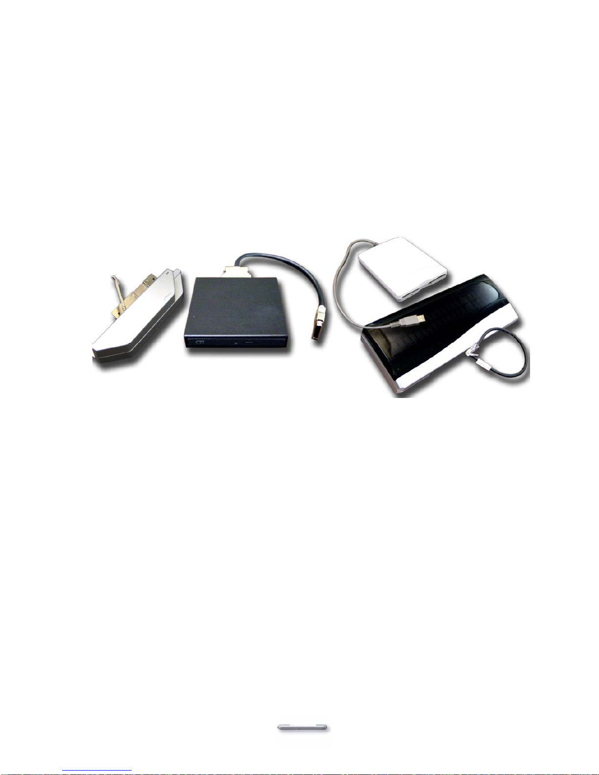
CD-ROM Installation..................................................................................................... 20
Cash Drawer Installation .............................................................................................. 20
Cash Drawer Activation................................................................................................ 21
CMOS Setup ....................................................................................................................... 21
Chapter
3
22
Chapter 3 22
Software Setup 22
Please follow this installation sequence exactly..................................................................22
Intel Chip Set Driver Installation for all Windows Operating Systems .................................22
VGA Driver Installation........................................................................................................ 24
852GME driver installation Windows 98 & ME............................................................. 24
852GME driver installation Windows 2000 & XP.......................................................... 27
Enable second LCD panel setting Windows 2000/Windows XP.................................. 29
LAN Driver Installation......................................................................................................... 33
Realtek LAN Driver Installation Windows 98................................................................ 33
Realtek LAN Driver Installation Windows 2000 and Windows XP................................ 35
Audio Driver Installation....................................................................................................... 36
Audio Driver Installation for all Windows Operating Systems....................................... 36
USB Driver Installation ........................................................................................................38
USB 2.0 Installation for Windows 98 & ME .................................................................. 38
USB 2.0 Installation for Windows 2000 and XP ........................................................... 39

ELO Touch Tools Installation .............................................................................................. 40
ELO Touch Tools Installation for Windows 98.............................................................. 40
ELO Touch Tools Installation for Windows 2000 and Windows XP............................. 42
ELO Control Panel ....................................................................................................... 45
TouchKit Tools Installation .................................................................................................. 48
TouchKit Tools Installation for all Windows Operating Systems .................................. 48
TouchKit Control Panel ................................................................................................ 51
Specifications 52
I/O board Configuration....................................................................................................... 54
9000PB0560 I/O Board Pin Definition.......................................................................... 54
9000PB0270 I/O Board Pin Definition.......................................................................... 60
Chapter
4
65
Chapter 4 65
Troubleshooting 65
Power is on, but there is no Panel Display................................................................... 65
Cannot Detect HDD...................................................................................................... 66
Primary Touch Panel Does not Work........................................................................... 66
ELO Touch Panel Cannot Calibrate Correctly.............................................................. 67
Second LCD Panel is Not Functioning Properly........................................................... 67
Second Touch Screen is Not Functioning Properly...................................................... 67
PS/2 Keyboard is not Functioning Normally................................................................. 68
MCR is not Functioning Properly.................................................................................. 68
VFD Display is not Functioning Properly...................................................................... 68
External CD-ROM is not Functioning Properly............................................................. 69
LAN is not Functioning Properly................................................................................... 69
COM1, COM2 and LPT1 are not Functioning Properly................................................ 69
Cash Drawer Port is not Functioning Properly ............................................................. 70
USB device is not Functioning Properly....................................................................... 70

FEB-4720 Main Board
2
C
Ch
ha
ap
pt
te
er
r
1
1
I
In
nt
tr
ro
od
du
uc
ct
ti
io
on
n
Model H800 Characteristics
¾Model H800 uses a high speed processor capable of handling a high capacity of data
efficiently.
¾Model H800’s solid quality Aluminum housing distinguishes it from ordinary plastic
housings.
¾Model H800 can function with multiple displays under Windows & Linux operating
systems. This allows for a variety of applications such as displaying commercial
information on the second LCD or as an interactive POS system.
¾The Model H800 touch terminal all-in-one design combines a powerful PC, multiple
LCD and touch screens, which are suitable for any market. The LCD panels can be
tilted at multiple angles.
¾Model H800 functionality extends far beyond the standard setup. Model H800 can be
adapted for a variety of uses with the addition of any of the following options: Magnetic
Card Reader, VFD/LCD customer display and cashdrawer, Modem, LAN, Audio
devices, Compact Flash or USB devices (all available upon request).
¾Model H800 security is designed to prevent data theft. The Model H800 system is
comprised of an internal 3.5” HDD and removable external CD-Rom and FDD making it
hard to copy data without authority.
¾The solid aluminum design enhances heat dissipation and passes EMI testing.

FEB-4720 Main Board
How to Use This Manual
This manual contains all the information you need to set up and use Model H800. In addition, you
can also consult the manuals for the operating system and added hardware.
Chapter 1 Provides an introduction to Model H800 and this manual.
Chapter 2 Provides all necessary information for all hardware setup.
Chapter 3 Provides the necessary information for installing the Intel Chip Set Driver, Video
drivers and the touch screen tools, Audio, USB and LAN drivers.
Chapter 4 Lists all Model H800 specifications and Information for the 9000PB0270 and
9000PB0560 I/O board configuration.
Chapter 5 Provides information for troubleshooting Model H800.
3

FEB-4720 Main Board
A Visual Tour of Model H800
Before you start, take a few moments to become familiar with Model H800.
What comes with Model H800
The following items are standard with Model H800:
¾Main system with primary LCD panel
¾Base with speakers
¾ATX power supply
¾Model H800 user’s guide
¾PEB 4720 motherboard user’s guide
¾Utility and Motherboard chipset driver CD
¾AC power cord
Model H800 with 2nd LCD, base with speakers and power adapter
Model H800 with MCR
Model H800 with VFD
4

FEB-4720 Main Board
The following items are optional:
¾Magnetic card reader (MCR) and bracket
¾External CD-ROM drive with cable
¾External USB floppy disk drive with cable
¾VFD customer display
¾Second LCD panel
¾Second Touch panel
Optional accessories
5

FEB-4720 Main Board
Dimensions
Model H800 Dimensions
Second LCD Dimensions
Model H800 and MCR Dimensions
6

FEB-4720 Main Board
Connector Panels
Primary Connector Panel
The primary connector panel is located on the bottom of the back on the main unit. To clearly see
the panel you must turn Model H800 upside down or remove the base.
RJ11
Cash Drawer
Connector
USB Sound
PS/2 Mouse
Connector Parallel
Connector
Power
Connector
COM2
LAN RJ45
Connector
COM1
I/O Port Connector Type Description
USB USB The USB (Universal Serial Bus) port can be used to
connect USB devices.
COM1
COM2 DSUB Connector The serial ports COM1/COM2 can be used to
connect serial devices such as a mouse or a
fax/modem.
LAN LAN RJ45 Connector The LAN port is used to hook Model H800 to a
local area network.
Sound Earphone Connector The audio port is for speakers.
Mouse PS/2 Mouse Connector PS2 ports can be used for a mouse.
LPT1 DSUB Connector The parallel port LPT1 can be used to connect
parallel devices, such as a printer.
Drawer RJ11 Connector Cash Drawer Connector, 12 V Actuation support for
solenoid.
Power DC Power Connector Connects Model H800 to the power supply.
7

FEB-4720 Main Board
Secondary Connector Panel
The secondary connector panel is located on left side of the back of the main unit. It comes with a
cover that needs to be removed to install a second LCD panel, touch screen, PS/2 Keyboard, CD
ROM Drive or a VFD customer display.
I/O Port Connector Type Description
VFD VFD/ COM4 RJ45
Connector The VFD port is used to attach An RJ45 cable
for a VFD customer display or second LCD
touch screen cable.
KBD PS/2 Keyboard Connector The KBD port for an external keyboard.
POWER 4 PIN DIN Connector The port supplies power for a second LCD.
VGA2 VGA Connector The VGA2 port is for the second LCD panel or
CRT monitor.
CD-ROM 36 PIN SCSI II Connector The CD-ROM port is used to attach an external
CD-ROM.
8

FEB-4720 Main Board
9
C
Ch
ha
ap
pt
te
er
r
2
2
H
Ha
ar
rd
dw
wa
ar
re
e
S
Se
et
tu
up
p
Model H800 Assembly
Please make sure that the system power is turned off and the power supply is disconnected when
making any hardware changes on Model H800.
Hard Disk Drive Installation
Model H800 comes with an empty hard disk Drive (HDD) unless a special request has been
made.
Installing a HDD
1. Turn off system power and remove power cable from Model H800.
2. Tilt the main LCD to 95 degrees.
3. Remove the 6 screws from the HDD metal cover
(using a small Phillips screwdriver) and lift off the
cover.

FEB-4720 Main Board
4. Remove the 3 screws holding the HDD frame in
place.
5. Attach the frame to the HDD (4 screws).
6. Connect the HDD power cable and IDE cable. The red stripe on the ribbon cable should be
aligned with PIN 1 on the IDE connector of HDD.
7. Reinstall the HDD frame with HDD attached in Model H800 (3 screws).
8. Replace cover and 6 screws.
9. Connect the main unit power.
Note: If the HDD does not work normally, please refer to troubleshooting.
10

FEB-4720 Main Board
Compact Flash Installation
Model H800 will configure Compact Flash in IDE mode as secondary master after it is installed.
The next available drive letter will be automatically assigned to Compact Flash.
Installing Compact Flash
1. Turn off system power.
2. Tilt the main LCD to 95 degrees.
3. Remove the 4 screws that attach the
Compact Flash cover to the main unit and
lift the cover off.
4. Insert Compact Flash and lock the black lever in a 90 degree position.
Black lever in a
90 degree
position
Compact Flash
5. Replace cover and 4 screws.
6. Turn on system power.
11

FEB-4720 Main Board
Second LCD Panel Installation
An optional second LCD panel can be easily installed on Model H800.
Installing second LCD panel
1. Turn off system power.
2. Remove the secondary I/O port
cover (1 screw).
3. Attach the second LCD to the back
of the main unit with 3 screws.
12

FEB-4720 Main Board
4. Attach the second LCD panel VGA
cable in the VGA2 port on the I/O
panel.
5. Attach the second LCD power cable
in the Power port on the I/O panel.
6. Turn on system power.
Note: If the second LCD does not work normally, please refer to troubleshooting.
13

FEB-4720 Main Board
OSD Settings for Second LCD Panel
Model H800 secondary LCD panel has built-in OSD (on screen display) controls to adjust various
display parameters. The control buttons are located on the right side of the back cover.
OSD Settings
There are four buttons on the OSD panel: Select, Down, Up, and Enter. The functions of these
four buttons are as follows:
Menu Press to open the OSD window.
Back one menu level up.
Press to exit the OSD window while in OSD mode.
DownArrow Press to scroll item selection bar down.
To decrease the parameter value.
To switch the item selection. (Ex: YES / NO).
UpArrow Press to scroll item selection bar up.
To increase the parameter value.
To switch the item selection. (Ex: YES / No).
Enter Enter the selected sub-menu.
Confirm selected function.
OSD Menu Structure
RGB Menu Brightness
Red -127~127
Green -127~127
Blue -127~127
Color Temp 0~7
Sharpness 0,1
Main Menu
14

FEB-4720 Main Board
Geometry Menu Auto-Adjustment
H. Position 0~252
V. Position 1~26
H. Total 1004~1108
Auto Phase
Delay 0~61
Main Menu
Contrast Menu Auto-Balance
Contrast
Red 0~511
Green 0~511
Blue 0~511
Balance
Red 0~127
Green 0~127
Blue 0~127
Main Menu 0~127
Language Menu English
Spanish
Main Menu
Auto Training ON/OFF
DOS/GFX ON/OFF
NVRAM init
Power Down
Revert
Save
15
Table of contents
Other OneTouch Touch Terminal manuals