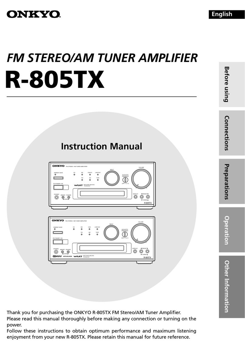
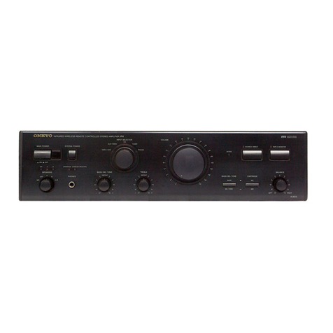
Onkyo TX-SV717PRO User manual

ONKYO.
Audio
Video
Control
Tuner
Amplifier
TX-SV717PRO
Instruction
Manual
laihaehtntlill
Gs
tists
Woes
spcsd0a
oni
sgn
nsir
cmd,
ocho?
tng
p
TIE
«
ag
oe

e
C
ongratulations
on
your
purchase
of
the
ONKYO
TX-SV717PRO
Tuner-Amplifier.
e
Please
read
this
manual
thoroughly
before
making
connections
and
turning
power
on.
@
Following
the
instruc-
tions
in
this
manual
will
enable
you
to
obtain
optimum
performance
and
listening
enjoyment
from
your
new
TX-SV717PRO.
e
Please
retain
this
manual
for
future
reference.
Important
safeguards
Precautions
........ssccccccsscrsreeteeeseees
FCACUIES:
i
vcecsccvsetscsevecvcessteesetestertensce
Before
using
this
unit
Listening
to
your
favorite
source
Using
the
tuner
.......cccccsssscceessesenees
Audio/Video
Recording
...........csssccsssesstseesesesessees
Basic
operation
of
Surround
play
Adjusting
the
Hall,
Live,
and
Studio
Surround
modes
CONTENTS
Explanation
.........scsccsccsssssecssessscsressseesseeseeseasscsesesscsssensoeenens
Prrrerrrrrrrrirrrerrrrrirririirininiro
yy
SySteM
CONNECHION
20...
ssscsessssscssesscesesecesecercsesecneacnscsonssesones
Control
positions
and
NAMES
...........ccseseseeersesereseeseeseeesereees
Using
the
On-screen
display
function
(This
function
is
done
entirely
with
the
remote
CONtrO])
..........sseseeeeeeeees
15
Pee
ee ee
eee
eens
ease
ease
enesese
neces
esse
senses
Sees
sees
seseeseensesereeesesenacsesaaneseneree
The
Parameter
Selector
........ccsscssscssccssscsssccscessesnssseessseenssens
Use
of
Surround
MOd€............ccccsssscssresssstsecssccscscseesesceeeesees
Adjusting
the
Dolby
Pro
Logic
Surround
.........:csseeessereees
Adjusting
the
Theater
Surround
..........ssscersencserseesseseresees
rrrerreritrrrrrirerrrirririrrrririiiiiririiiiiiiiir
yy
Pence
een
er
eev
reser
ese
e
eres
eeenes
a
eee
sere
reser
er
eeesenaeeeeeneeeneeeeereneeeneneneassnnwens
Prrerererrrtrrrrstirrrrrririirrriii
rir
POC
ee
eee
eee
eee eee
eneeeeeeeeseeenee
reece
eee
e
sees
seeeeeesere
ses
OneeeeeHenesarnaeneeeseensl
Listening
to
devices
connected
to
the
TX-SV717PRO
in
another
room
Learning
remote
control
codes
using
the
10
programmable
buttons
....
Trouble
shooting
guide
..............000
suasbrstese
dasouduueraveaclestadsoasducessescsaucedeSudcssnelsuctarnstseteasesstdstute
cousin
sdeeahestess
.
Specifications
...........cceccssesesrsenes
sPbcwstdosavdaisiscecebssesetsioa
sbesSueSasesonces
asudsatavacetuetsconsnYS-vseduaecotandeuetce
doduuessecusebhatonscesusecssensesen
.39
CAUTION:
“WARNING”
“TO
REDUCE
THE
RISK
OF
ELECTRIC
SHOCK,
DO
NOT
REMOVE
COVER
(OR
BACK).
NO
USER-SERVICEABLE
PARTS
INSIDE.
RE-
FER
SERVICING
TO
QUALIFIED
SERVICE
PERSONNEL.”
CAUTION
RISK
OF
ELECTRIC
SHOCK
DO
NOT
OPEN
@
The
lightning
flash
with
arrowhead
symbol,
within
an
equilateral
triangle,
is
intended
to
alert
the
user
to
the
presence
of
uninsulated
“dangerous
voltage”
within
the
product's
enclosure
that
may
be
of
sufficient
mag-
nitude
to
constitute
a
risk
of
electric
shock
to
persons.
@
The
exclamation
point
within
an
equilateral
triangle
is
intended
to
alert
the
user
to
the
presence
of
important
operating
and
maintenance
(servicing)
instructions
in
the
literature
accompanying
the
appliance.
“TO
REDUCE
THE
RISK
OF
FIRE
OR
ELECTRIC
SHOCK,
DO
NOT
EXPOSE
THIS
APPLIANCE
TO
RAIN
OR
MOISTURE.”
e
For
models
having
power
cords
with
a
polarized
plug.
CAUTION:
To
PREVENT
ELECTRIC
SHOCK,
MATCH
WIDE
BLADE
OF
PLUG
TO
WIDE
SLOT,
FULLY
INSERT.
e
Sur
les
modéles
dont
la
fiche
est
polarisée.
ATTENTION:
pour
eviteR
LES
CHOCS
ELEC-
TRIQUES,
INTRODUIRE
LA
LAME
LA
PLUS
LARGE
DE
LA
FICHE
DANS
LA
BORNE
CORRESPONDANTE
DE
LA
PRISE
ET
POUSSER
JUSQU
AU
FOND.
Read
Instructions
—
All
the
safety
and
operating
instructions
should
be
read
before
the
appliance
is
operated.
Retain
Instructions
—
The
safety
and
operating
instructions
should
be
retained
for
future
reference.
Heed
Warnings
-
All
warnings
on
the
appliance
and
in
the
operating
instructions
should
be
adhered
to.
Follow
Instructions
—
All
operating
and
use
instructions
should
be
followed.
Water
and
Moisture
—
The
appliance
should
not
be
used
near
water
-
for
example,
near
a
bathtub,
washbowl,
kitchen
sink,
laundry
tub,
in
a
wet
basement,
or
near
a
swimming
pool,
and
the
like.
Carts
and
Stands
—
The
appliance
should
be
used
only
with
a
cart
or
stand
that
is
recommended
by
the
manufacturer.
6A.An
appliance
and
cart
combina-
10.
11.
12.
13.
14.
tion
should
be
moved
with
care.
Quick
stops,
excessive
force,
and
uneven
surfaces
may
cause
the
appliance
and
cart
combination
to
overturn.
PORTABLE
CART
WARNING
$3125
-_
—-
Wall
or
Ceiling
Mounting
—-
The
appliance
should
be
mounted
to
a
wall
or
ceiling
only
as
recommended
by
the
manu-
facturer.
Ventilation
—
The
appliance
should
be
situated
so
that
its
location
or
position
does
not
interfere
with
its
proper
ventilation.
For
example,
the
appliance
should
not
be
situated
on
a
bed,
sofa,
rug,
or
similar
surface
that
may
block
the
ventilation
open-
ings;
or,
placed
in
a
built-in
installation,
such
as
a
bookcase
or
cabinet
that
may
impede
the
flow
of
air
through
the
ventilation
openings.
Heat
—
The
appliance
should
be
situated
away
from
heat
sources
such
as
radiators,
heat
registers,
stoves,
or
other
appli-
ances
(including
amplifiers)
that
produce
heat.
Power
Sources
—
The
appliance
should
be
connected
to
a
power
supply
only
of
the
type
described
in
the
operating
instruc-
tions
or
as
marked
on
the
appliance.
Polarization
—
!f
the
appliance
is
provided
a
polarized
plug
having
on
blade
wider
than
the
other,
please
read
the
following
information;
The
polarization
of
the
plug
is
a
safety
feature.
The
polarized
plug
will
only
fit
the
outlet
one
way.
If
the
plug
does
not
fit
fully
into
the
outlet,
try
reversing
it.
If
there
is
still
trouble,
the
user
should
seek
the
services
of
a
qualified
electrician.
Under
no
circumstances
should
the
user
attempt
to
defeat
the
polariza-
tion
of
the
plug.
Power-Cord
Protection
—
Power-supply
cords
should
be
routed
so
that
they
are
not
likely
to
be
walked
on
or
pinched
by
items
placed
upon
or
against
them,
paying
particular
attention
to
cords
at
plugs,
convenience
receptacles
and
the
point
where
they
exit
from
the
appliance.
Cleaning
—
The
appliance
should
be
cleaned
only
as
recom-
mended
by
the
manufacturer.
Power
Lines
—
An
outdoor
antenna
should
be
located
away
from
power
lines.
15.
Nonuse
Periods
—
The
power
cord
of
the
appliance
should
be
unplugged
from
the
outlet
when
left
unused
for
a
long
period
of
time.
16.
Object
and
Liquid
Entry
—
Care
should
be
taken
so
that
objects
do
not
fall
and
liquids
are
not
spilled
into
the
enclosure
through
openings.
17.
Damage
Requiring
Service
—
The
appliance
should
be
ser-
18.
viced
by
qualified
service
personnel
when:
A.
The
power-supply
cord
or
the
plug
has
been
damaged;
or
B.
Objects
have
fallen,
or
liquid
has
been
spilled
into
the
appli-
ance;
or
C.
The
appliance
has
been
exposed
to
rain;
or
D.
The
appliance
does
not
appear
to
operate
normally
or
exhib-
its
a
marked
change
in
performance;
or
E.
The
appliance
has
been
dropped,
or
the
enclosure
dam-
aged.
Servicing
—
The
user
should
not
attempt
to
service
the
appli-
ance
beyond
that
described
in
the
operating
instructions.
All
other
servicing
should
be
referred
to
qualified
service
personnel.
19.
Outdoor
Antenna
Grounding
—
!f
an
outside
antenna
is
connected
to
the
receiver,
be
sure
the
antenna
system
is
grounded
so as
to
provide
some
protection
against voltage
surges
and
built
up
static
charges.
Article
810
of
the
National
Electrical
Code,
ANSI/NFPA
70,
provides
information
with
regard
to
proper
grounding
of
the
mast
and
supporting
structure,
grounding
of
the
lead-in
wire
to
an
antenna
discharge
unit,
size
of
grounding
conductors,
location
of
the
antenna-discharge
unit,
connection
to
grounding
electrodes,
and
requirements
for
the
grounding
electrode.
See
Figure
73.1.
FIGURE
73.1:
EXAMPLE
OF
ANTENNA
GROUNDING
AS
PER
NATIONAL
ELECTRICAL
CODE
ANTENNA
LEAD
IN
WIRE
ANTENNA
DISCHARGE
UNIT
(NEC
SECTION
810-20)
ELECTRIC
SERVICE
EQUIPMENT
GROUNDING
CONDUCTORS
(NEC
SECTION
810-21)
GROUND
CLAMPS
POWER
SERVICE
GROUNDING
ELECTRODE
SYSTEM
(NEC
ART
250,
PART
4)
NEC
-
NATIONAL
ELECTRICAL
CODE
S2898A
Note
to
CATV
system
installer
This
reminder
is
provided
to
call
the
CATV
system
installer’s
atten-
tion
to
Article
820-40
of
the
NEC
which
provides
guidelines
for
proper
grounding
and,
in
particular,
specifies
that
the
cable
ground
shall
be
connected
to
the
grounding
system
of
the
building,
as
close
to
the
point
of
cable
entry
as
practical.

1.
Warranty
Card
The
serial
number
is
written
on
the
rear
panel
of
this
unit.
Copy
the
serial
number
and
model
number
onto
your
warranty
card
and
keep
it
in
a
safe
place.
Recording
Copyright
Recording
of
copyrighted
material
for
other
than
personal
use
is
illegal
without
permission
of
the
copyright
holder.
3.
AC
Fuse
The
fuse
is
located
inside
the
chassis
and
is
not
user
service-
able.
If
power
does
not
come
on,
contact
your
ONKYO
service
center.
4.
Care
From
time
to
time
you
should
wipe
off
the
front
and
rear
panels
and
the
cabinet
with
a
soft
cloth.
For
heavier
dirt,
dampen
a
soft
cloth
in
a
weak
solution
of
mild
detergent
and
water
or
a
mild
ammonia
cleaner,
wring
it
out
dry,
and
wipe
off
the
dirt.
Following
this,
dry
immediately
with
a
clean
cloth.
Do
not
use
rough
mate-
rial,
thinners,
alcohol
or
other
chemical
solvents
or
cloths
since
these
could
damage
the
finish
or
remove
the
panel
lettering.
5,
Power
BEFORE
TURNING
ON
POWER
FOR
THE
FIRST
TIME,
READ
THE
FOLLOWING
SECTION
CAREFULLY.
e
Some
models
are
designed
for
use
only
with
the
power
supply
voltage
of
the
region
where
they
are
sold.
U.S.A.
and
Canadian
models:
AC
120V,
60Hz
Worldwide
models:
120
and
220V
switchable,
50/60Hz
ns
Features
5-Mode
DSP
(Digital
Signal
Prossesor)
Voltage
Selector
(Rear
Panel)
Worldwide
models
are
equipped
with
a
voltage
selector
to
conform
with
local
power
supplies.
Be
sure
to
set
this
switch
to
match
the
volt-
age
of
the
power
supply
in
your
area
before
turning
the
power
switch
on.
Voltage
is
changed
by
sliding
the
groove
in
the
switch
with
a
screwdriver
to
the
right
or
left.
Confirm
that
the
switch
has
been
moved
all
the
way
to
the
right
or
left
before
turning
the
power
switch
on.
Models
without
a
voitage
selector
can
only
be
used
in
areas
where
the
power
supply
is
the
same
as
that
of
the
unit.
220V,
120V
220V%,
120V™
at
AC120V
at
AC220V
Tuning
Step
Frequency
Switch
(Rear
Panel)
Worldwide
models
are
equipped
with
a
switch
that
controls
the
AM
(9kHz/10kHz)
band
tuning
steps.
Be
sure
to
set
this
switch
to
match
the
tuning
step
frequency
in
your
area.
DSP
enhances
any
audio
or
A/V
source
be
providing
five
acoustic
“environments”,
Hall,
Theater,
Live,
Studio
and
Dolby
Pro
Logic
Surround.
Full
Digital
Dolby
Pro
Logic
Dolby
Pro
Logic
gives
you
a
center
channel
to
keep
movie
dialogue
firmly
locked
on
the
screen.
Surpassing
analog,
it
is
completely
digital
to
give
you
clearer
separation,
better
sound
imaging
and
improved
localization.
Easy-to-use
On-Screen
Displays
They're
easy
to
understand,
and
tell
you
practically
everything
you
need
to
know.
Four
simple
cursor
buttons
on
the
remote
control
let
you
operate
the
displays,
even
in
a
completely
darkened
room.
Plenty
of
Clean
Power
All
five
channels
use
discrete
output
stage
amplifiers,
so
you
can
easily
drive
low-impedance
loads.
In
stereo
mode
you
get
110
watts
per
channel
into
8
ohms,
to
the
Front
speakers.
Surround
mode
gives
you
85
watts
per
channel
into
8
ohms,
to
the
Front
Left,
Right
&
Center
speakers,
and
30
watts
per
channel
into
8
ohms,
to
the
Rear/Remote
speakers.
Multiple-Room
Remote
System
and
Multi-Source
Selector
4
Video
and
6
Audio
inputs
(Selectable)
Direct
Access
Tuning
40-Station
Random
Preset
Tuning
&
6-Group
Classified
Memory
8
Heavy-Duty
Four-Way
Banana
Plug
Speaker
Terminals
Compatible
Programmable
Remote
Control
Supplied

Surround
system
Many
motion
pictures
produced
in
the
last
decade
have
been
released
in
“Dolby
Stereo”
sound,
with
music,
dialogue,
and
panned
effects
coming
from
the
3-channel
front
soundstage,
and
surround
effects
and
ambience
emanating
from
the
sides
and
rear
of
the
theater.
These
four
channels
are
encoded,
or
matrixed,
into
a
two-channel
DOLBY
STEREO
release,
and
decoded
in
the
theater
by
a
professional
DOLBY
STEREO
MP
(Motion
Picture)
decoder.
These
surround
sound
effects
are
“hidden”
in
the
two-channel
stereo
movie
release,
and
decoded
in
the
theater
by
special!
Dolby
equipment.
These
same
two-channel
motion
picture
masters
are
used
for
production
of
stereo
VHS,
VHS-Hi-Fi,
Beta
Hi-Fi,
and
stereo
Laser
Vision
discs
that
you
can
buy
or
rent
at
your
video
store.
The
TX-SV717PRO
incorporates
the
Digital
Dolby
Pro
Logic
Surround
Circuit,
which
is
designed
to
emulate
the
audience
experience
found
in
DOLBY
STEREO
theaters.
Like
Dolby
Surround,
Dolby
Pro
Logic
Surround
is
capable
of
creating
a
multi-dimen-
sional
soundstage,
but
with
the
increased
channel
separation
it
gives
a
far
greater
sense
of
“movement”
and
sound
localization.
Just
like
in
the
the-
ater,
the
addition
of
the
active
Center
channel
ensures
that
all
audience
members
hear
dialogue
coming
from
its
on-screen
sources
regardless
of
seating
position.
Since
the
TX-SV717PRO
is
equipped
with
Front
amplifiers,
Center
amplifier
and
rear
(Surround)
amplifiers,
Dolby
Pro
Logic
Surround,
Theater,
Hall,
Live
and
studio
effects
can
all
be
produced.
You
can
enjoy
the
feeling
of
a
movie
theater
or
concert
hall
in
your
own
room.
To
reproduce
these
effects,
Rear
(Surround)
speakers
and
center
speaker
are
necessary.
The
placement
of
these
speakers
is
important.
You
can
experiment
with
var-
ious
positions
and
locations
to
find
the
best
placement
for
optimum
sound
quality
in
your
room.
DSP
(Digital
Signal
Processor)
The
DSP
converts
the
musical
signal
into
digital
form
and
produces
reflected
sound
from
the
digital
signal.
This
is
applied
to
the
musicai
signal
to
yield
an
effect
approaching
that
of
a
live
performance.
all
reflections
Stage
reflections
ATU
ISSN
<<
“TLIO
Wall
reflections
NOTE:
The
same
kind
of
sound
and
natural
expansion
of
sound
that
you
experience
in
a
theater
or
concert
hall
can
be
achieved
in
your
listening
room.
Hall
mode
would
be
best
suited
to
jazz
and
classical
music.
The
concert
hall
effect
is
produced
from
the
reflections
and
reverberations
contained
in
the
original
recording.
These
are
converted
into
reflected
sound
that
is
reproduced
from
four
directions.
Thus,
in
some
cases
an
unnatural
impression
can
be
conveyed
if
there
are
too
few
reflections
in
the
recording
or
if
the
effects
in
the
original
recording
were
produced
artificially.
The
concect
hall
effect
is
not
merely
an
artificial
reverberation
unit,
but
a
sophisticated
effect
that
spreads
existing
reverberation
around.
Multiple
Room
Remote
System
(mR)
The
ONKYO
HR-10(W)
Remote
Sensor
(sold
separately)
greatly
increases
system
flexibility.
Used
with
your
TX-SV717PRO,
the
HR-1
0(W)
allows
you
to
control
speakers
even
when
you
are
not
in
the
same
room
as
the
TX-SV717PRO.
In
addition
to
basic
functions
like
speaker
on-off
and
volume
and
so
on,
you
can
also
control
most
ONKYO
CD
players,
cassette
decks
and
digital
audio
tape
decks
that
use
the
FRI
system.
Adding
an
HE-
50(AGC)
Remote
Emitter
(also
available
as
an
option)
allows
you
to
control
even
the
non-ONKYO
components
in
your
home
entertainment
system
from
a
separate
room.
When
the
HE-50(AC)
is
being
used
to
control
more
than
one
device
from
a
distance
but the
infrared
beams
from
the
HE-50(AC)
remote
control
alone
will
not
reach
these
devices,
connect
an
HE-10
(Remote
Emitter
head)
to
the
HE-50(AC),
and
set
it
up
to
be
aimed
at
the
devices
to
be
controlled.
The
HW-2
cable
6-1/2’
(2m)
is
attached
with
the
HE-10.
Up
to
three
HE-10
units
can
be
used
with
this
equipment.*
Manufactured
under
license
from
Dolby
Laboratories
Licensing
Corporation.
Additionally
licensed
under
one
or
more
of
the
following
pat-
ents:
U.S.
number
3,959,590:
Canadian
numbers
1,004,603
and
1,037,877.
“Dolby”,
“Pro
Logic”,
and
the
double-D
symbo!
D0
are
trade-
marks
of
Dolby
Laboratories
Licensing
Corporation.
|
|

Before
using
this
unit
Supplied
accessories
OT
g
(AM
loop
(T-shaped
FM
antenna
x
1)
antenna
x
1)
Remote
control
battery
insertion
a)
<2
Remote
sensor
approx.
5m
(16
feet)
Remote
control
(RI
remote
control
cable
x
1)
Batteries
x
2)
(Remote
control
x
1
Loading
the
batteries
Remove
the
battery
compartment
cover
by
opening
it
as
shown
in
the
figure.
Load
two
AA
(R6)
size
batteries
with
the
plus
(+)
and
minus
(-)
terminals
positioned
as
indicated
by
the
diagram
inside
the
bat-
tery
compartment
and
close
the
cover.
e@
When
the
batteries
lose
their
power,
the
indicator
on
the
remote
control
will
flash
when
any
button
is
pressed.
@
Remove
dead
batteries
immediately
to
avoid
corrosion
damage.
e
To
avoid
potential
corrosion
damage,
never
mix
old
batteries
with
new
ones.
e
Learned
codes
are
not
lost
even
when
the
batteries
are
replaced.
They
may
be
lost,
however,
if
battery
replacement
is
not
com-
pleted
within
an
hour.
In
this
case,
the
unit
must
learn
the
codes
again.
e@
The
manganese
batteries
supplied
with
this
unit
have
a
service
life
of
approximately
six
months,
depending
on
frequency
of
usage.
e@
The
TX-SV717PRO
comes
equipped
with
AA
(R6)
manganese
batteries,
but
we
recommend
that
long-life
alkaline
batteries
AA
(LR6)
be
used
when
replacing
the
batteries.
Precautions
e
This
unit
uses
infrared
rays.
Therefore,
commands
may
not
be
received
properly,
if
the
Front
panel
of
the
TX-SV717PRO
is
exposed
to
bright
light.
To
prevent
this
from
occurring,
place
the
TX-SV717PRO
so
that
it
is
not
directly
exposed
to
brightlight.
e@
If
the
TX-SV717PRO
is
placed
inside
an
audio
rack
behind
a
glass
door,
the
door
should
not
use
colored
glass
or
have
any
decorations
on
it
since
this
could
shorten
the
range
or
prevent
commands
from
being
received.
e
Use
of
other
infrared
remote
control
devices
in
the
same
room
may
cause
interference.
e
The
remote
control
operates
up
to
a
distance
of
about
five
meters
(16
feet).
The
transmitting
window
must
always
be
pointed
at
the
reception
window
when
a
command
is
sent
to
the
TX-SV717PRO.
e
If
the
remote
control
does
not
operate
properly,
confirmthat
the
batteries
are
not
dead.
If
the
problem
persists,
contact
your
Onkyo
Service
Center.
Memory
preservation
The
TX-SV717PRO
itself
does
not
require
memory
preservai
on
bat-
teries.
A
built-in
memory
power
back-up
system
preserves
[me
con-
tents
of
the
memory
during
power
failures
and
even
when
the
unit
is
unplugged.
The
unit
must
be
plugged
in in
order
to
charge
tte
back-
up
system.
The
memory
preservation
period
after
the
unit
has
been
urp
lugged
varies
depending
on
climate
and
placement
of
the
unit.
On
the
aver-
age,
memory
contents
are
protected
over
a
period
of
a
few
weeks
af-
ter
the
last
time
the
unit
has
been
unplugged.
This
period
is
shorter
when
the
unit
is
exposed
to
a
highly
humid
climate.

System
connection
Do
not
plug
in
the
mains
power
cord
until
all
other
connections
have
been
made.
As
the
sound
quality
of
this unit
will
diminish
if
the
left
and
right
channels
are
reversed,
ensure
that
the
left
and
right
channel
connections
are
correct.
When
jacks
on
other
equipment
or
connection
cables
are
color
coded
the
color
red
usually
corresponds
to
the
right
channel.
(Red
=
Right)
@
Antenna
(4)
Amplifier
(3)
Speaker
(6)
Connections
for
remote
control
connections
conections
conections
@
Conections
for
Multiple
Room
|
Remote
System
Fsses)
eet
of
OOOOOOO}
a
+O
S0.0-00}
'OOOOG
TAPE
fae
OETA
ee
HORSE
(2)
Audio
video
connecttions
(6)
AC
Outlets
Worldwide
models
are
equiped
with
a
voltage
selector
and
a
tuning
frequency
switch.
jo
ee
1.
Antenna
connections
FM
indoor
antenna
connection
FM
outdoor
antenna
connection
Move
the
antenna
in
various
directions
until
the
clearest
signal
Keep
the
antenna
away
from
noise
sources
(neon
signs,
busy
is
received.
Fix
it
with
push
pins
in
the
position
with
the
least
roads
etc.)
It
is
dangerous
to
put
it
close
to
power
transmission
amount
of
distortion.
cables,
so
keep
it
well
away.
(USA
and
Canadian
models)
(USA
and
Canadian
models)
eNTEND
ANTENNA
(Worldwide
models)
(Worldwide
models)
GF
=D
ANTENNA
Cal
ANTENNA
=m
AM
ied
LO
——€)-
FM
752
NOTE:
If
the
reception
is
not
very
clear
with
the
attached
T-shaped
an-
tenna
the
use
of
an
external
antenna
is
recommended.
E
;
:
:

How
to
connect
a
75/300
ohm
antenna
adapter
(included)
(worldwide
models
only)
Connecting
a
coaxial
cable
1.
With
your
fingernail
or
a
small
screwdriver,
press
the
stopper
outwards
and
remove
the
cover.
2.
Prepare
the
coaxial
cable
as
shown
below.
3.
Connect
the
75/300
ohm
antenna
adapter
to
the
coaxial
cable
_
——
ara
6
31
6
1.
Remove
the red
cord.
2.
Insert
the
end
of
the
cable.
3.
Clamp
in
place
with
pliers
Connecting
a
T-shaped
FM
antenna
or
300
ohm
FM
outdoor
antenna
(worldwide
models)
feeder
FM/TV
Indoor
Outdoor
T-shaped
‘cdi
eee
eaeneey,
antenna
a
Ea
300
ohm
AM
indoor
antenna
connection
Set
it
to
the
direction
where
you
can
receive
the
clearest
sound,
and
as
far
away
from
the
main
unit
as
possible.
If
you
bring
it
closer
to
the
connecting
wires
you
may
get
some
interference.
(USA
and
Canadian
models)
AM
loop
antenna
ANTENNA
(Worldwide
models)
ANTENNA
NOTE:,
Where
reception
is
unsatisfactory
with
the
attached
AM
loop
antenna
alone,
it
is
recommended
that
you
attach
an
external
antenna.
Directional
linkage
A
(os
Directional
linkage
type
splitter
To
receiver
To
TV
(or
VCR)
NOTE:
Do
not
use
the
same
antenna
for
both
FM
and
TV
(or
VCR)
re-
ception
since
the
FM
and
TV
(or
VCR)
signals
can
interfere
with
each
other.
If
you
must
use
a
common
FM/TV
(or
VCR)
anten-
na,
use
a
directional
linkage
type
splitter.
AM
outdoor
antenna
connection
Do
not
remove
the
AM
loop
antenna.
The
external
antenna
will
be
more
effective
if
you
stretch
it
hor-
izontally
in
a
high
place
above
a
window,
or
outside.
(USA
and
Canadian
models)
more
than
5m
(16
feet)
of
vinyl
cable
(commercia!)
Outdoor
AM
antenna
ANTENNA
(Worldwide
models)
Outdoor
AM
antenna
ANTENNA
AM
reception
is
easily
affected
by
television
sets
and
VCRs.
Therefore,
AM
reception
may
be
poor
if
this
unit
is
placed]
too
close
toa
TV
ora
VCR.

2.
Audio
video
connections
Please
refer
to
each
device's
instruction
manual
regarding
operation
and
installation
procedures
and
precautions.
Audio
components
connection
A
ground
connection
is
not
necessary
for
turnable
without
ground
leads.
CD
piayer
When
connecting
a
graphic
equalizer
and
other
(second)
tape
deck
to
the
TAPE-2
jacks,
connect
them
as
follows.
TX-SV717PRO
Cassette
tape
deck
(TAPE-2)
Graphic
equalizer
REC
(LINE
IN
)
Cassette
tape
deck
(TAPE-1)
>
|=
|
oa
[Ss
O
VIDEO
IN
|
|
Monitor
TV
MONITOR
pak
VIDEO-3
;
VIDEO
PLAY
(LINE
OUT)
Second
tape
deck
REC
(LINE
IN)
‘:
Video
components
connection
CASSETTE
RECORDER
VIDEO-2
VIDEO
CASSETTE
RECORDER
—
OUTPUT
4
AUDIO.
VIDEO
VIDEO-1
VIDEO
DISC
[OUTPUT
4
PLAYER
or
AUDIO
VIDEO
VIDEO
CASSETTE
RECORDER
Front
panel
When
the
audio
output
of
the
video
equipment
is
monaural,
connect
to
the
R
audio
input
jocks.
VIDEO-4
VIDEO
DISC
PLAYER
—ourPuT-
VIDEO
CAMCORDER
AUDIO
VIDEO
VIDEO-4/VIDEO
CAM
INPUT

3.
Speaker
connections
Connecting
the
speakers
If
you
want
to
use
the
Surround
effects,
the
Rear
and
Center
speakers
must
be
connected.
Please
refer
to
“Connecting
the
Center
speaker(s)”
below
when
connecting
Center
speaker(s).
The
speakers
that
are
to
be
located
in
the
same
room
as
the
TX-
SV717PRO
should
be
connected
to
the
MAIN
speaker
terminals.
Different
sets
of
speakers
that
are
to
be
located
in
another
room
(or
the
same
room)
should
be
connected
to
the
REMOTE
speaker
terminals.
To
get
the
full
effects
of
the
Surround
processor,
ensure
the
left
and
right
Front
and
Rear
speakers
are
not
reversed.
SPEAKERS
SPEAKERS
(MAIN)
(MAIN)
L
SPEAKERS
SPEAKERS
Se
ou
NOG
Oo
2
©
CENTER
CENTER
NOTES:
e
Do
not
connect
a
single
speaker
in
parallel
to
the
right
and
left
channel
outputs.
e
Use
speaker
cables
that
have
a
low
impedance
and
that
are
as
short
as
possible.
e
SPEAKER
IMPEDANCE
FRONT
MAIN:
6
ohms
min/speaker
SINGLE
CENTER,
REMOTE,
REAR:
8
ohms
min/speaker
DUAL
CENTER:
4
ohms
min/speaker
SPEAKERS
(REMOTE)
Connecting
the
Center
speaker‘(s)
Connecting
the
speaker
cables
(When
using
2
Center
(When
using
1
Center
4
speakers)
speaker)
i
a
inin
cs
—
Ee
R
is
—_—_—
twist
copper
strands
remote
insulation
together
insert
here
G
k
unscrew
NOTE:
When
using
banana
plugs,
make
sure
the
speaker
terminal
screws
are
screwed
in
firmly
before
insert-
CENTER CENTER
CENTER
ing the
banana
plugs.
tighten
CENTER

Speaker
placement
Placing
the
speakers
for
Surround
effects
Speaker
placement
plays
an
important
role
in
the
reproduction
of
sound
using
Surround.
The
manner
in
which
the
speakers
are
placed
varies
de-
pending
on
the
size
of
the
room
and
the
wall
coverings
used
in
the
room.
The
following
shows
an
example
of
a
layout
for
standard
speaker
place-
ment.
Refer
to
the
example
for
placing
the
speakers
appropriately
in
order
to
experience
the
best
of
Surround
sound.
in
principle
for
Surround
sound
reproduction,
two
Front
speakers
and
two
Surround
(Rear)
speakers
are
required.
Refer
to
the
illustration
on
the
left.
Placing
the
Front
speakers
Projector
or
Monitor
TV
(L)
(R)
er,
sound
spreads
out too
much
and
is
dispersed
resulting
in
a
dimin-
cy
=
Ss
ished
sound
quality.
Y
Front
speaker
Front
speaker
If
the
Front
L
and
R
speakers
are
placed
too
far
away
from
each
oth-
Y
Rear
speaker
(Surround)
Rear
speaker
(Surround)
Ss
Cc
Placing
the
Rear
speakers
To
bring
out
the
feeling
of
shifting
sound,
the
Rear
speakers
should
not
be
placed
on
the
floor,
but
would
be
most
effective
placed
above
ear
position.
They
can
also
be
placed
facing
the
ceiling
or
walls
to
re-
flect
the
sound.
Placing
the
Center
speaker
°
(3
Bin}
saat
8
Center
speaker
Center
speakers
To
enjoy
Dolby
Pro
Logic
Surround
or
Theater
reproduction,
a
Center
speaker
is
required
in
addition
to
the
four
basic
speakers.
When
one
Center
speaker
is
used
If
a
screen
with
a
projector
is
used,
place
the
Center
speaker
under
the
screen.
If
a
Monitor
TV
is
used,
it
is
recommended
that
the
Center
speaker
be
placed
on
top
of
or
under
the
Monitor.
When
two
Center
speakers
are
used
Ptace
the
Center
speakers
on
the
left
and
right
sides
of
the
monitor
TV
as
close
as
possible
to
the
screen,
facing
slightly
inward.
They
can
be
placed
on
top
and
under
the
TV.
Please
use
magnetic-proot
type
speakers,
otherwise
the
speakers
might
cause
uneven
colors
on
the
screen
of
the
monitor
TV.
Placing
a
Subwoofer
speaker
To
enjoy
powerful
bass
sounds,
install
a
subwoofer
with
a
built-in
power
amplifier.
The
placement
of
the
Subwoofer
does
not
affect
the
final
quality
of
the
sound
image
too
much,
therefore
as
its
exact
placement
is
not
critical,
you
can
install
it
more
with
the
room
layout
in
mind.
To
especially
enjoy
A/V
Surround,
a
Subwoofer
can
bring
out
the
best
features
of
Dolby
Pro
Logic
Surround.
10

4.
Amplifier
connections
NOTES:
5.
Connections
for
remote
control
TS-SV717PRO
Green
Black
Lallo
oun)
©
REMOTE
CONTROL
I
REMOTE
CONTROL
COMPACT
DISC
PLAYER
Ri
REMOTE
CONTROL,
CASSETTE
TAPE
DECK
RI
REMOTE
on=
CONTROL,
@
No
signals
will
be
output
from
FRONT,
REAR,
CENTER
and
MONO
PRE
OUT
when
the
SPEAKERS
MAIN
button
is
turned
off.
@
No
signals
will
be
output
from
MULTI
SOURCE
PRE
OUT
when
the
SPEAKERS
REMOTE
button
is
turned
off.
The
TX-SV717PRO
is
equipped
with
a
set
of
PRE
OUT
terminals
which
allow
you
to
connect
an
external
power
amplifier.
With
a
powerful
power
amp,
you
can
play
music
at
even
higher
volume
levels
than
with
the
TX-SV717PRO
alone.
Connect
the
power
amp
to
the
PRE
OUT
terminals
of
the
TX-SV717PRO,
and
connect
the
speakers
to
the
power
amp.
Rear
power
amplifier
INPUT
©)
L
Rear
(Surround)
speakers
©)R
Center
power
amplifier
INPUT
©)
Center
speaker
Subwoofer
amplifier
INPUT
Subwoofer
speaker
©)
Front
power
amplifier
INPUT
6)
L
Front
Main
L
and
R
speakers
©)
Multi-source
power
amplifier
INPUT
6)
‘i
Front
Remote
L
and
R
speakers
©)
R
{another
room)
A
cassette
tape
deck
and
compact
disc
player
that
have
the
ONKYO
fR1
mark
can
be
operated
using
the
accessory
remote
control
with
the
TX-SV717PRO.
Connect
a
remote
control
cable
to
the
black
jack
with
the
RI
mark.
Never
connect
it
to
the
green
jack
with
the
MTR
mark.
Connect
the
remote
control
cable
as
shown
left
side
to
enable
remote
control
operation
of
other
components.
‘NOTES:
e@
To
enable
proper
remote
contro!
operation,
both
the
fRI
cable
and
the
audio
cables
must
be
connected
between
units.
e@
The
TX-SV717PRO
remote
control
cannot
be
used
to
control
ONKYO
turntables.
e@
An
RI
remote
control
cable
equipped
with
a
1/8”
(3.5
mm)
min-
iature
2
conductor
phone
plug
is
included
with
the
TX-
SV717PRO
and
with
any
other
component
with
the
fR4
mark.
6.
AC
Outlets
AC
OUTLETS
°
{e)
oO
SWITCHED
TOTAL
120W
MAX
i
11
The
shape
and
power
loading
capacity
of
the
outlets
differs
depend-
ing
on
the
region.
The
USA
&
Canadian
model
is
shown.
USA
&
Canadian
model:
1A
120
watts
max.
Worldwide
model:
100
watts
max.
SWITCHED
These
outlets
are
switched
on
and
off
by
the
power
button
on
the
Front
panel,
and
on
the
remote
control.

7.
Connections
for
Multiple
Room
Remote
Control
When
using
only
the
HR-10
(optional)
to
control
the
TX-SV717PRO
in
the
main
room
from
another
room,
connect
them
as
shown
in
below.
In
this
case,
both
the
ONKYO
CD
player
and
the
cassette
tape
deck
bear-
ing
the
(R41
mark
and
connected
to
the
TX-SV717PRO
can
be
controlled.
REMOTE
Loudspeaker
set
MAIN
Loudspeaker
set
Another
room
Remote
control
iGreen
jterminal
i
Rear
panel
of
the
TX-SV717PRO
V
V
FRONT
SPEAKERS
MAIN
—
.
i
a
|
|
SENS
our
owfT]}ne
=O
ONKYO
4E10
Bottom
of
HR-10
to
REMOTE
speakers
Note
on
mR
cables
to
approximately
164’
(50
m)
lengths
are
generally
practical.
and
164’
(50m)
(HW-50).
(ONKYO
cables
may
not
be
sold
in
some
regions.)
To
enable
remote
contro!
operation
when
the
TX-
S$V717PRO
is
mounted
in
a
rack
which
will
not
permit
in-
fra-red
beams
to
pass,
mount
the
HR-10
somewhere
outside
the
rack
that
will
pick
up
the
signals.
If
all
com-
ponents
bear
the
FI
mark,
connect
a
MR
cable
from
the
HR-10
to
the
MIR
input
on
the
TX-SV717PRO,
and
from
there
connect
RE
cables
to
the
other
components
(see
page
11).
If
the
other
components
can
receive
in-
frared
remote
contro!
signals,
but
do
not
have
the
RI
mark,
mount
an
HE-50(AC)
inside
the
cabinet
so
that
signals
from
it
will
reach
the
sensors
in
all
components,
and
connect
it
to
the
HR-10
with
an
MR
cabie.
Remote
control
qaooo];
%
3
o
Oooool}®
2:
HE-SO(AC)
|
CASSETTE
TAPE
DECK
NTE
TCT
|
COMPACT
DISC
PLAYER
A
connection
example
using
the
HR-10
(optional)
and
HE-50
(AC)
(optional)
to
control
components
in
the
main
room
from
another
room
is
shown
below.
If
all
the
components
can
not
be
controlled
by
the
HE-50
(AC)
alone
because
they
are installed
at
various
places
in
the
main
room,
use
a
Remote
Emitter
head
HE-10
(optional).
This
also
allows
you
to
control
components
that
are
not
ONKYO,
or
do
not
have
an
fRI
mark,
as
long
as
they
can
be
controlled
by
infrared
remote
control.
When
using
an
HE-50(AC),
the
HE-50(AC)
or
HE-10
should
also
face
the
TX-SV717PRO.
Any
remote
sensors
and
emitters
(HR-10,
HE-50(AC),
HE-10)
should
be
connected
with
low
capacitance
shielded
2-wire
coaxial
cables
with
1/8”
(3.5
mm
diameter)
mini-plug
connectors.
Maximum
cable
length
is
determined
by
the
characteristics
of
the
particular
cables
used
but
up
Ready
made
cables
complete
with
mini-plug
connectors
are
available
in
the
following
lengths:
6-1/2’
(2m)
(HW-2),
98-7/16'
(30m)
(HW-30),
Refer
to
the
instruction
manual
which
comes
with
the
HR-10
when
making
these
connections.
Sets
of
loudspeakers
in
another
room
should
be
connected
to
the
TX-SV717PRO
in
the
main
room
with
low
impedance
cables.
MAIN
MAIN
Loudspeaker
set
Loudspeaker
set
AC
adaptor
to
AC
i
Bottom
or
HE-50
(AC}
ADAPTOR
a
ary
q
Rear
panel
of
the
TX-SV717PRO
"
REMOTE
Loudspeaker
set
Remote
control
Q
Green
toHe-10
)
our
~
600
\
)
POWER
:
S
+o
ONEYO
2:0
SENS
our
)
|
Low
HIGH
©
ONKEYO
te.15
REMOTE
CONTROL
Bottom
of
HR-10
to
HE-10
eset
“NOTES:
to
REMOTE
speakers
e@
Always
unpiug
the
AC
power
cords
for
the
TX-SV717PRO
and
HE-50(AC)
when
connecting
the
MR.
@
Insert
the
MR
mini-plug
into
the
green
terminal
on
the
Rear
panel
of
the
TX-SV717PRO.
12
silmeein
Ba
G
e

Control
positions
and
names
For
more
information
about
buttons
or
controls,
turn
to
the
page
number
listed
in
the
brackets
after
each
item.
Front
panel
ONEYO
aii
vioco
contro
©
stano.uy
:AeceweD
ALL
CHANNE(S
DISCHETE
SPEAKERS
OUTPUT
STAGE
cet
DIGITAL
SOUNDFIELDY
PROCESSOR
Mi
RECOUT
SOURCE
(1)
Power
button
(POWER)
[17]
(2)
Remote
control
sensor
(3)
Dimmer
button
(DIMMER)
[14]
(4
Surround
mode
button
(SURROUND
MODE)
25,
28,
31,
33]
()
Parameter
selector
buttons
(PARAME-
TER
SELECTOR)
[25,
28,
31,
33]
(6)
Parameter
controller
buttons
(PARAM-
ETER
CONTROLLER)
[25,
28,
31,
33]
@
Memory
button
(MEMORY)
[20]
(8)
Direct
access
tuning
button
(DIRECT
TUNING)
[19]
(@)
Number
buttons
(1
to
9,
0)
Classified
memory
scan
button
(CLASSIFIED
SCAN)
[20]
1)
Selective
tone
control
button
(SELECTIVE
TONE)
[18]
Display
(2)
Volume
control
knob
and
_
indicator
(MASTER
VOLUME)
[18]
43)
Balance
control
knob
(BALANCE)
[18]
(4)
Treble
control
knob
(TREBLE)
[18]
(5)
Bass
control
knob
(BASS)
[18]
46
Tuning
selector
buttons
(DOWN,
UP)
[19]
qd?
FM
muting/mode
button
(FM
MUTE/MODE)
[19]
Input
selector
buttons
Audio
selectors
(CD,
PHONO,
FM,
AM,
TAPE-1,
TAPE-2
MONITOR)
Video
selectors
(VIDEO-1
VDP/CDV,
VIDEO-2
VCR,
VID-
EO-3
VCR,
VIDEO-4
VIDEO
CAM)
SPEAKERS
[_MAIN
|
>
TONG
fore
STEREO
REMOTE]
(lem
ute
VIDEO
‘OFF
_j
[poLsy
PRO
LOGIC
|
[HALL
|
[THEATER]
(“uve
]
[STUDIO
|
TAPE-2
|
MONITOR
|
(9)
Classified
memory
buttons
(CLASS-A
to
CLASS-F)
[20]
0)
Multi-source
button
(MULTI
SOURCE)
[34]
21)
VIDEO-4
input
jack
(VIDEO-4/VIDEO
CAM
INPUT)
[8]
@2)
Recording
out
button
(REC
OUT)
[21-24]
@3)
Headphone
jack
(PHONES)
[18]
24)
MR
off
button
(MMR
OFF)
and
indicator
[34]
@5)
Speaker
selector
buttons
(SPEAKERS
MAIN/REMOTE)
[17]
AUDIO
MUTING
}
MEMORY
WZ)
Bune
@
‘SURAOUND
MODE»
SLEEP
Etim
[Souace
[uice0-1}
WOEO
2]
[VIDEO-3|
fwoeo-4)
[Tare-+j
[TAPe-2
{onde
|[PHoNo
[co
|
(IEEE
()
Video
input
selector
indicators
@)
Speaker
selector
indicators
@
FM
muting
on/off
indicator
(
FM
stereo
indicator
©)
Audio
muting
indicator
©
Tuned
indicator
@)
Memory
indicator
13
Sleep
indicator
@)
Selective
tone
control
indicator
(0
Multi
function
display
Preset
station
/
sleep
timer
/
multi-
source
volume
level
/
delay
time
/
cen-
ter,
rear
volume
level
(1)
Multi
function
display
Frequency
/
input
selector
(2)
Recording
out
/
multi-source
indicators
43)
Tape-2
monitor
indicator
(4)
Surround
mode
indicators
|

Remote
Control
-
SENDING
A
‘LEARN
(2)
fo]
oN
rowen
)
afk
aan
/amwoTe
ORME
(7)
)
HO)
C9
COCO
CO
ae
~~.
SOUHCF
SELECTOR
————___
cot
o&
6)
le
©
GG
on em
Ces
eae
ve)
DISC
~~
ENTER:ESCAPE
oS
:
(6)
(4
oxrson
»
(5)
|
a
oe
v
on om
(om)
omy
DECK-A
=
=
CECK
B
=
(Re
|
OS
ole:
on
.
om
.
ue
|
(7)
sae)
C5
@|Cor
(14)
wintry
Sibaa|y
Sas.
Sow?
||
oom
cD
ea/4
(3)
(8)
Ii
|C!l
|
7a
||
NE
|
eer
|
ae
(9)
cms)
(eos)
|[cmn)
|
(cos)
(es)
(2)
DELAY
DOWN
OWN
ONK
Rl
UNIVERSAL
PHOGRAMMABLE
REMOFE
RC-253m
|
PS)
Saas
@
C1)
A/B/LEARN
selector
switch
(A/B-SUBROOM/LEARN)
[34,
35,
36]
This
switch
is
used
for
three
functions
A
—
When
using
the
remote
control
in
the
main
room.
All
of
the
buttons
on
the
remote
control
can
be
used.
(The
PROGRAMMA-
BLE
AREA
TV/VIDEO
buttons
can
be
used
when
memorizing
remote
control fuction
of
TV
and
Video
equipment.)
B
—
When
using
the
remote
control
in
the
subroom.
Only
the
buttons
that
are
underlined
and
have
bule
writing
can
be
used.
These
buttons
are
shaded
on
the
illustration
above.
(2)
Learned/sending
indicator
[35]
(3)
Power
button
(POWER)
@)
Input
selector
buttons
(Video
1
to
4,
PHONO,
CD,
TUNER,
TAPE-1,
TAPE-2)
(6)
PROGRAMMABLE
AREA
TV/VIDEO
buttons
[35]
You
are
able
to
use
these
buttons
when
memorizing
remote
con-
trol
functions
of
TV
and
video
equipment.
For
details,
please
refer
to
“Learning
remote
control
codes
using
the
10
programma-
ble
buttons”
on
page
35.
©
CD
operation
buttons
These
buttons
are
used
to
operate
an
ONKYO
CD
player
with
the
RI
mark.
@
Tape
operation
buttons
(DECK-A,
DECK-B)
These
buttons
control
ONKYO
double
cassette
tape
decks
that
can
be
remote
controlled.
Use
the
DECK-B
buttons
to
control
single
cassette
tape
decks
with
the
FRI
mark.
Surround
mode
button
(SURROUND
MODE)
[25,
27, 28, 31,
33]
(9)
Delay
time
button
(DELAY
TIME)
[30]
Rear
level
up/down
buttons
(REAR
LEVEL
UP/DOWN)
[30]
Center
level
up/down
buttons
(CENTER
LEVEL
UP/DOWN)
d)
Audio
muting
button
(MUTING)
This
button
temporarily
switches
off
the
sound
from
the
speakers
or
headphones
by
operating
the
TX-SV717PRO
audio
muting
circuits.
The
audio
muting
indicator
MUTING
will
flash.
Pressing
the
button
again
or
using
the
POWER
button
on
the
remote
con-
trol
to
turn
the
power
on
will
turn
off
the
audio
muting.
Audio
muting
using
this
button
does
not
affect
the
sound
of
the
multi-source
(Remote
speakers).
Press
the
SPEAKERS
REMOTE
to
mute
the
sound
of
the
multi-
source.
42)
Volume
buttons
(VOLUME
UP/DOWN)
[18,
34]
When
adjusting
the
level
of
the
Front
Main,
Center
or
Rear
(Sur-
round)
speakers,
set
the
A/
B-SUB
ROOM
/
LEARN
switch
to
A,
and
use
these
buttons.
When
adjusting
the
level
of
the
Remote
speakers
(perhaps
in
another
room),
set
the
A
/
BSSUB
ROOM
/
LEARN
switch
to
B,
and
use
these
buttons.
43)
Test
tone
button
(TEST)
[29]
Use
buttons
(8)
-
(1)
when
playing
back
in
Surround
mode.
@4
Tuner
operation
buttons
(TUNER)
[19]
Class
selector
button
(AM/FM)
(CLASS)
Preset
memory
up/down
buttons
(PRESET
UP/DOWN)
(5
On-screen
cursor
buttons
(CURSOR
a,
¥,
<,
>)
[15]
On-screen
enter/escape
buttons
(ENTER/ESCAPE)
Use
these
buttons
when
operating
using
the
On-screen
display.
For
details,
please
refer
to
the
explanations
on
page
15
and
for
the
operation
of
each
On-screen
item.
DIMMER
button
(DIMMER)
This
button
can
be
used
to
change
the
brightness
of
the
display.
The
display
brightness
changes
in
three
steps
(bright,
medium,
dim).
(
Speaker
selector
buttons
(SPEAKERS
MAIN
/
REMOTE)
[17,
34]
48
Sleep
button
(SLEEP)
Press
to
set
the
power-off
timer.
The
sleep
timer
is
a
function
which
turns
off
the
power
to
the
system
after
a
certain
period
from
the
time
it
is
set.
When
this
button
is
pressed,
“90
MIN”
is
displayed
for
5
seconds,
and
the
power
will
go
off
90
minutes
later.
Each
time
the
button
is
pressed
during
5
seconds,
the
timer
setting
changes
by
10
minutes
e.g.
80,
70,
60
...
While
the
sleep
timer
is
operating,
the
SLEEP
indicator
is
lit.
If
the
sleep
button
is
pressed
during
this
time,
the
amount
of
time
remaining
on
the
timer
is
displayed,
and
if
the
button
is
pressed
during
that
display,
10
minutes
will
be
subtracted
from
that
time.
{f
the
button
is
pressed
when
the
panel
display
shows
10
minutes
or
less,
the
sleep
timer
is
cancelled,
and
the
power
is
not
turned
off.
14

The
On-screen
display
function
is
only
available
when
an
NTSC
TV
system
is
used.
It
will
not
work
with
other
systems
such
as
PAL,
SECAM
etc.
The
On-screen
function
uses
a
monitor
TV
connected
to
the
TX-SV717PRO
as
a
display,
and
is
classified
into
two
categories.
The
Immediate
display
This
is
the
indication
shown
when
the
Input
Selector,
the
volume
of
the
Center/Rear/Front
speakers
or
the
Surround
mode
is
changed.
The
message
will
automatically
disappear
after
3
seconds.
However,
this
does
not
apply
when
the
unit
is
in
the
muting
mode
or
the
test
tone
is
turned
on.
The
Menu
screen
This
is
the
display
shown
when
the
ENTER/ESCAPE
on
the
remote
control
is
pressed.
The
menu
screen
can
be
operated
by
means
of
cursor
buttons
on
the
remote
control.
The
monitor
TV
should
be
connected
to
the
TX-SV717PRO
to
utilize
this
function.
Immediate
display
The
following
items
will
be
shown
on
the
display
during
the
operation
of
the
TX-SV717PRO
main
unit
or
remote
control.
When
the
power
of
TX-SV717PRO
is
When
the
Input
selector
is
changed.
When
the
Surround
mode
is
changed.
turned
on.
TAPE-1
VIDEO-1
Theater
When
the
MUTING
is
pressed
on
the
When
the
TEST
is
pressed
on
the
When
pressing
the
CENTER
UP/
remote
control.
remote
control.
DOWN
or
REAR
UP/DOWN
on
the
remote
control.
Muting
Test
Rear
t
weve
re vy
Using
the
menu
screen
This
operation
is
performed
using
the
remote
control.
These
buttons
are
used
to
set
the
Input
Selector,
the
Rec
Selector,
the
Surround
Setup
and
the
Screen
Setup.
ENTER/ESCAPE
button
e
Used
to
select
the
menu
screen.
ENTER/ESCAPE
button
CURSOR
buttons
A
V:
Used
to
move
the
cursor
upward
and
downward
on
the
screen.
CURSOR
buttons
<4
>:
Used
to
move
the
cursor
to
the
left
and
right
on
the
scieen,
and
to
change
the
parameters
or
select
the
items
on
which
thecursor
is
located.
e@
Holding
down
the
button
will
change
the
parameter
or
move
the
cursor
continuously.
e
Cursor
is
black
and
white
reversed
characters
on
the
sceen.
On-screen
displays
video
images
in
the
background
when
a
video
source
is
playing,
and
displays
text
on
top
of
your
selected
colour
on
scre=
n
when
nothing
is
being
played
back.
On-screen
is
output
only
to
the
MONITOR
OUT
terminal,
not
to
the
record
terminal
(out).
Therefore,
even
if
any
On-screen
is
displayed
on
twe
mon-
itor
TV
while
recording,
the
On-screen
display
is
not
recorded.
Menu
items
on
each
screen
differ
according
to
the
Surround
mode
etc.
Pressing
the
<
or
®
buttons
while
the
cursor
is
on
some
items
ma
display
a
separate
sub-screen.
15

Basic
operation
.
1.
Press
the
ENTER/ESCAPE
button.
ee
RK
Menu
x
KKK
ENTER/ESCAPE
2.
Select
the
desired
menu
using
the
a
or
y
CURSOR
buttons.
A
CURSOR
v
G2)
The
screen
changes
as
follows
Please
refer
to
the
page
inside
the
parentheses
for
details
about
each
screen.
3.
Press
the
ENTER/ESCAPE
button
again.
ee
Screen
Set
tip:
oF
Background
C0
lor
=
OB)
ENTER/ESCAPE
Immediate
s
Display
=
ON
@-
4.
Select
the
desired
item
using
the
a
or
vy
CURSOR
buttons
and
change
the
parameters
and
conditions
of
the
items
using
the
<
or
»
CURSOR
buttons.
5.
Press
the
ENTER/ESCAPE
button
after
all
the
desired
conditions
have
been
input.
e@
The
screen
will
display
the
main
menu.
6.
Use
the
a
or
¥
CURSOR
buttons
to
select
Menu
Off.
Press
the
ENTER/ESCAPE
button
again
to
turn
the
Menu
screen
off.
e
Repeat
steps
2
-
5
in
order
to
use
the
other
functions.
When
an
item
is
selected
with
the
CURSOR
buttons
&
or
W
on
the
Surround
Setup
screen
and
the
<
or
»
CURSOR
buttons
are
pressed,
another
item
may
disappear,
or
in
some
cases
the
cursor
may
skip
over
some
items.
Input
Selector
screen
Menu
screen
Surround
Setup
eRe
Menu
eR
®
ICICI
ESICS)
**
Screen
Setup
**
Backgrou
Imnmedi
Screen
Setup
menu
When
you
select
the
Screen
Setup
menu,
the
following
display
appears
on
the
On-screen
display.
Background
color
You
can
select
the
background
color
among
8
colors.
Select
the
number
of
the
corresponding
color
from
1
to
8.
The
numbers
corre-
spond
to
the
following
numbers
in
the
table.
1
4
White
|
Yellow
|
Black
Blue
Green
|
Cyan
Please
note
that
the
above
color
descriptions
are
standard
descrip-
tions.
The
actual
colors
may
differ
depending
on
the
tone
and
bright-
ness
adjustments
of
the
projector
or
TV
used.
When
there
is
an
image
input
signal,
the
input
signal
will
be
used
for
the
background.
Therefore
the
background
color
which
you
have
se-
lected
will
not
be
displayed.
The
lettering
shown
by
the
On-screen
display
will
be
white.
Immediate
display
When
Immediate
display
is
set
to
ON,
the
Immediate
display
will
be
shown,
and
when
it
is
set
to
OFF,
the
Immediate
display
will
not
be
shown.
When
Menu
Off
is
chosen,
the
selected
background
color
will
not
be
displayed.
This
can
be
useful
when
you
don’t
want
to
display
the
message,
or
when
you
want
to
check
the
Auto/Manual
tuning
for
TV/
BS
devices
connected
to
the
Image
input.
16
4
|
FO
EU
er
a
Pe
NES
AED
ETT
ay
aE
RE
a
TT
EE
SE
eRe
TS
RS
ea
Pe
ney
gal
ee
eRe
Pee

POWER
SPEAKER
VOLUME
ca
09
Input
Selectors
Tone
Balance
SPEAKERS
SOURCE
SELECTOR
VOLUME
Operating
the
main
unit
1.
Press
the
POWER
button
to
turn
on
the
power.
POWER
©
STAND-BY
/
RECEIVED
2.
Press
the
MAIN
speaker
selector
button.
SPEAKERS
MAIN
REMOTE
MAIN
indicator
lights
up.
3.
Press
the
desired
Input
Selector
button.
VIOEO-2
|
WIDEG-3
|
VIDEO
4
VCR
von
e@
The
button
pressed
will
be
shown
on
the
display.
For
FM
or
AM
reception,
the
band
and
the
frequency
will
also
be
shown.
e
Confirm
that
the
TAPE-2
MONITOR
indicator
is
off
when
a
source
other
than
the
TAPE-2
MONITOR
has
been
selected.
Also
check
the
audio
muting
is
off.
e
Please
refer
to
the
operations
from
page
25
onward
in
order
to
play
the
selected
source
with
Surround.
Explanation
of
the
buttons
Power
button
(POWER)
and
STAND-BY/
RECEIVED
indicator
The
STAND-BY/RECEIVED
indicator
comes
on
when
the
AC
power
cord
for
this unit
has
been
inserted
in
an
outlet.
This
indicates
that
the
TX-SV717PRO
is
standing
by
for
operation.
Pressing
the
POWER
button
or
remote
control
POWER
button
will
turn
the
main
unit
on,
and
power
will
be
supplied
from
the
AC
outlet
to
the
rear
panel.
This
indicator
then
goes
off.
The
indicator
also
lights
when
a
signal
is
re-
ceived
from
the
remote
control.
17
4.
Start
the
selected
input
source
playing.
e
Follow
the
operating
instructions
of
that
unit.
5.
Adjust
the
volume
to
appropriate
level
using
the
MASTER
VOLUME
knob.
BALANCE
Speaker
selector
buttons
(SPEAKERS
MAIN/
REMOTE)
and
indicators
You
can
operate
the
Speaker
selector
from
the
Front
panel
or
with:
the
remote
control.
When
MAIN
and/or
REMOTE
is
on,
the
MAIN
or
REMOTE
SPEAKER
indicators
will
light.
MAIN
speakers
button
The
speakers
connected
to
the
MAIN,
CENTER,
and
REAR
speaker
terminals
can
all
be
switched
on
or
off
at
the
same
time.
REMOTE
speakers
button
This
button
is
used
to
turn
on
or
off
the
Remote
speakers
connected
to
the
REMOTE
speaker
terminals.
The
source
selected
using
MULTI
SOURCE
will
be
used
for
the
Remote
speakers
(see
on
page
34).
When
the
multi-source
is
being
used,
you
can
use
the
SPEAKERS
REMOTE
button
to
turn
the
Remote
speakers
on
or
off.

Master
volume
control
knob
(MASTER
VOL-
UME)
Use
the
master
volume
control
knob
to
adjust
the
volume
of
the
Front
Main,
Center
and
Rear
(Surround)
speakers,
at
the
same
time.
Turn
clockwise
to
increase
the
volume
level.
The
volume
can
be
adjusted
manually
and
by
the
remote
control’s
VOLUME
UP/DOWN
buttons.
The
master
volume
contro!
knob
rotates
when
the
volume
is
adjusted
by
remote
control.
To
adjust
the
volume
level
of
the
remote
speakers,
switch
the
A/B-SUBROOM/LEARN
selector
switch
to
the
B-SUB-
ROOM
position
and
use
the
VOLUME
UP/DOWN
buttons
on
the
re-
mote
control.
To
adjust
the
volume
while
the
Surround
effects
or
the
multi-source
are
being
used,
refer
to
each
section:
Using
the
Surround
effects
(see
page
29)
Using
the
multi-source
(see
page
34)
Tone
and
Balance
Controls
Bass
Control
Knob
(BASS)
Adjust
to
strengthen
or
weaken
bass
response.
(Not
effective
for
the
Center
or
Rear
speakers,
or
multi-source
signal.)
Treble
Control
Knob
(TREBLE)
Adjust
to
strengthen
or
weaken
treble
response.
(Not
effective
for
the
Center
or
Rear
speakers,
or
multi
source
signal.)
TREBLE
and
BASS
are
effective
only
for
the
Front
L
and
R
speakers.
The
best
results
are
obtained
from
DOLBY
PRO-LOGIC
SUR-
ROUND
when
the
Center
and
Front
L
and
R
speakers
contain
the
same
amounts
of
mid
and
high
frequencies.
As
the
treble
and
bass
controls
do
not
affect
the
Center
speaker,
adjust
the
tone
controls
for
the
Front
L
and
R
speakers
to
match
the
sound
given
by
the
Center
speaker.
Because
of
this,
we
recommend
the
use
of
a
good
quality
Center
speaker.
Using
headphones
PHONES
Balance
control
knob
(BALANCE)
Use
the
balance
control
knob
(BALANCE)
to
adjust
the
relative
vol-
ume
levels
of
the
left
and
right
Main
speaker
systems.
This
adjusts
the
relative
volume
level
of
the
Front
Main
speaker
systems
only.
Selective
tone
control
button
(SELECTIVE
TONE)
and
indicator
The
selective
tone
control
is
used
to
clearly
reproduce
ultra
low
and
high
frequencies,
and
only
affects
the
Front
speakers.
(Does
not
af-
fect
the
Rear
speakers
or
multi
source
signal.)
Stereo
headphones
with
a
standard
binaural
(stereo)
plug
can
be
connected
to
the
phones
jack.
The
sound
heard
through
the
head-
phones
is
the
sound
from
the
Front
speakers,
but
may
sound
a
little
different
to
what
was
heard
from
the
speakers
(it
may
sound
relative-
ly
far
away).
When
operating
with
the
cursor
on
the
screen
using
the
remote
control
1.
Press
the
ENTER/ESCAPE
button.
keke
Menu
RRR
Tn
pbb
oS
ede
e
tours
Rec
Selector
Surround
Setup
Screen
Setup
ENTER/ESCAPE
Menu
Of
f
Picture
Indicates
the
input
source
of
the
picture.
To
change
the
input
source,
press
the
<
or
®
CURSOR
buttons
while
the
cursor
is
located
on
Picture.
Sound
Indicates
the
input
source
of
the
sound.
To
change
the
input
source,
press
the
<
or
®
CURSOR
buttons
while
the
cursor
is
located
on
Sound.
When
you
press
the
<
or
®
CURSOR
buttons
while
the
cursors
are
on
both
Picture
and
Sound,
you
can
change
the
input
source
of
the
Picture
and
Sound
at
the
same
time.
However
if
you
select
other
than
VIDEO-1
to
4
for
the
input
source,
the
image
will
be
fixed
to
the
most
recently
selected
video
source
so
that
only
the
sound
changes.
2.
Move
the
cursor
to
Input
Selector
and
press
the
ENTER/ESCAPE
button.
oe
Tipe
Seer
e
eetiorr
|
ee
Picture
=
VIDEQO-1
@aw)
Sound
=
TUNER
@ab)
TAPE-2
Moni.=
OFF
Qe)
Ciass
=
F
@*®
Preset
=
40ch
@*®
Sur.Mode
=
BY-PASS
ORAS]
TAPE-2
moni.
indicates
TAPE-2
MONITOR
ON/OFF.
When
you
press
the
<
or
»
CURSOR
buttons
while
the
cursor
is
located
on
TAPE-2,
the
moni-
toring
will
be
switched
to
ON/OFF.
Sur.
Mode
Each
input
source
can
have
a
different
Surround
mode
assigned
to
it,
so
the
Surround
mode
position
will
be
automatically
set
according
to
which
input
source
of
sound
you
choose.
The
current
Surround
mode
will
be
shown
on
screen.
Therefore
each
time
you
change
the
input
source
of
the
sound,
the
display
will
also
be
changed.
To
change
the
Surround
mode
assigned
to
the
current
input
source,
press
the
<
or
®
CURSOR
buttons
while
the
cursor
is
located
at
Surround
Mode.
See
page
26
for
further
details
regarding
the
Sur-
round
mode.
18

Please
make
sure
that
the
TAPE-2
MONITOR
indicator
is
off
and
audio
muting
is
off.
DIRECT
TUNING
FM
MUTE/MODE
MEMORY
CLASSIFIED
MEMORY
=
FM,AM
Number
button
CLASSIFIED
SCAN
TUNING
TUNER
CLASS
PRESET
UP/DOWN
Tuning
with
the
TUNING
buttons
1.
Press
either
the
AM
or
FM
Input
Selector
button.
Tuning
using
the
DIRECT
TUNING
button
1.
Press
either
the
AM
or
FM
Input
Selector
button.
e@
if
the
frequency
for
the
desired
station
is
known,
you
can
input
the
frequency
number
directly.
2.
Press
the
DIRECT
TUNING
button.
Y
4
DIRECT
sure
vese8
TUNING
4 N
“.
-"will
flash
for
16
seconds
in
the
Frequency
display.
—
3.
Input
the
desired
frequency
number
by
using
the
Number
buttons
while
the
cursors
are
flashing.
e
For
instance,
if
you
wish
to
receive
the
station
at
88.10MHz
Using
the
FM
MUTING/MODE
button
FM
MUTE
FM
MUTE
>
FM
MUTE/MODE
ON
|
ERASE
—
19
Press
one
of
the
tuner
selector
buttons.
TUNING
When
you
press
the
UP
or
DOWN
button,
the
frequency
increases
or
decreases.The
frequency
is
changed
in
50kHz
steps
in
FM
and
10
kHz
(or
9
kHz)
in
AM
when
the
tuning
selec-
tor
button
is
pressed
in
single
steps.
If
this
button
is
held
continuously
for
more
than
0.5
seconds,
the
auto
tuning
mode
is
entered
and
the
frequencies
are
scanned
automatically.
When
a
broadcast
is
received,
scanning
stops.
:
*
MHz
Press
8, 8,
1
and0
When
receiving
AM
broadcasts
with
a
9kHz
step
(this
depends
on
your
region),
you
can
enter
the
frequency
directly.
With
10kHz
steps,
entering
a
number
for
the
10kHz
digit
will
set
the
1kHz
digit
automatically
to
0.
If
the
desired
frequency
set
in
this
operation
does
not
exist,
the
frequency
which
is
the
nearest
to,
and
lower
than
the
desired
frequency
will
be
received.
If
the
frequency
set
is
not
in
the
receivable
frequency
range,
the
frequency
flashes
for
two
sec-
onds,
and
the
previous
frequency
will
be
displayed.
If
a
wrong
frequency
has
been
set,
press
the
DIRECT
TUNING
button
and
start
again.
To
listen
to
FM
stereo
broadcasts,
turn
the
muting
on.
The
ON
indi-
cator
will
light
up.
When
a
stereo
broadcast
is
received,
the
STEREO
indicator
will
light
up.
When
the
broadcast
is
too
weak
to
be
received
in
stereo,
turn
the
muting
off.
The
OFF
indicator
will
light
up.
In
the
off
setting,
even
weak
stations
can
be
received.
Other manuals for TX-SV717PRO
1
Table of contents
Other Onkyo Amplifier manuals

Onkyo
Onkyo A-5VL - Integrated Stereo Amplifier User manual

Onkyo
Onkyo TX-860 User manual

Onkyo
Onkyo TX-108 User manual

Onkyo
Onkyo TX-61 User manual

Onkyo
Onkyo TX-844 User manual

Onkyo
Onkyo TX-906 User manual

Onkyo
Onkyo R-100 User manual

Onkyo
Onkyo TX-820 User manual

Onkyo
Onkyo TX-SV444 User manual

Onkyo
Onkyo A-9150 User manual

Onkyo
Onkyo TX-SV909PRO User manual

Onkyo
Onkyo TX-SV525 User manual

Onkyo
Onkyo A-9355 User manual

Onkyo
Onkyo M-5010(B) User manual

Onkyo
Onkyo A-8850 User manual

Onkyo
Onkyo A-809 User manual

Onkyo
Onkyo A-9155 User manual

Onkyo
Onkyo M-5000R User manual

Onkyo
Onkyo TX-DS838 User manual

Onkyo
Onkyo TX-26 User manual