Onkyo TX-NR3030(B) User manual

TX-NR3030
RC-884M
1110 12
DIMMER DISPLAY
D.TUN
PLAYLISTPLAYLIST
SETUP RETURN
TV
REMOTE MODE
/
INPUT SELECTOR
HOME
PREV CH
MENU
GUIDE
TOP MENU
RC-884M
RECEIVER SOURCE
REPEAT RANDOM MODESEARCH
ZONE 3GREEN
2RED
REMOTE MODE
SLEEP
VOL
INPUT
123
456
789
0
+10
CLR
ENTER
ALBUM
CH
DISC
Q
GAME
TUNER
TV
/
CD
BD/ DVD
PC AUX
PHONO
STB / DVRCBL / SAT
MUTING
MODE
RECEIVER
TV
VOL
MOVIE/ TV
MUSIC
THX
GAME
ALL OF F
MY MOVIE
MY TV
MY MUSIC
BLUETOOTH
USBNET
(European and
Asian models
AV RECEIVER
Black and Silver models
MODEL TX-NR3030(B)/(S)
Ref. No. 4478
102014
120V AC, 60Hz
220-240V AC, 50/60Hz
B MDC
B MMP, S MMP
B MMR

TX-NR1030/3030/ PR-SC5530/ DTR-60.6/70.6/ DHC-80.6
DEBUG MODE-1
AUDIO DEBUG MODE-1/4
To set in Debug mode
1. Press twice the ON/STANDBY key while pressing the DISPLAY key.
The version number of microprocessor is displayed
only for 3 seconds.
The version number of DSP is displayed
only for 3 seconds.
AUDIO DEBUG MODE (Display mode of the audio information)
The operations of DSP and DIR etc are able to checked by the information displayed on FL in this debug mode.
This information will help to analysing digital audio no sound trouble.
Audio dubug mode
Step-1
Exit
e.g. Main:
1.01/13515AE8
2. Press
+
(TONE) button while the version number of microprocessor is displayed.
3. Press DISPLAY button while the version number of DSP is displayed.
DSP 1st/NET:
1.07/13514AEA
e.g.
0A0002: :00
ANA:o:NON: :
4. Press DISPLAY button.
SP00F*00F00409
48 48256STB
2:o:PCM :PCM
00:x:F:OFF
1:ANA 048k048k
2/0.0: 2.0:3/4
9. Press DISPLAY button.
8. Press DISPLAY button.
6. Press DISPLAY button.
5. Press DISPLAY button.
11. Press DISPLAY button.
12. Press DISPLAY button.
10. Press DISPLAY button.
7. Press DISPLAY button.
13. Press DISPLAY button.
LW : 0 0
RW : 0 0
LB : 0 0
RB : 0 0
LH : 0 0
RH : 0 0
LS : 0 0
RS : 0 0
C : 0 0
L : 0 0
R : 0 0
SW : 0 0
SW2 : 0 0
Step-2
Step-11
Step-10
Step-9
Step-8
Step-7
Step-6
Step-5
Step-4
Step-3
14. Press DISPLAY button.
e.g.
e.g.
e.g.
e.g.
e.g.
e.g.
e.g.
e.g.
e.g.
e.g.
e.g.

TX-NR1030/3030/ PR-SC5530/ DTR-60.6/70.6/ DHC-80.6
DEBUG MODE-2
AUDIO DEBUG MODE-2/4
Step-1
112233
:
AA
:
BB
CCC
:
D
:
EEE
:
F
:
G
A
Muting port
D
A
DIGMUTE port
AMUTE port
Factor of muting
B
bit_2 POWMUTE
bit_5 AUDIOMUTE
bit_3 PROTECTMUTE
bit_4 AUDIOOUTMUTE
bit_1 SELMUTE
Sound state
E
STB SOUND STATE FIX
NON SOUND STATE NONE
TRS SOUND STATE UNFIX
C
Input
ANA Analog
COX Caxal
OPT Optical
HDM HDMI
ARC ARC
Display inhibit
F
S
C
display_inhibit SET
display_inhibit CLR
DSP Detect
D
×DSP No Detect
○DSP Detect OK
HDMI mute
G
V HDMI MUTE
st_srd.lmd
C_LM_LAST01
C_LM_PURE02
C_LM_DIRECT03
C_LM_STEREO04
C_LM_MONO05
C_LM_SURR20
C_LM_THX_MUSIC50
C_LM_THX_GAME70
C_LM_THX_CINEMA90
C_LM_THX_U2GAMEA0
C_LM_THX_U2MUSICA8
C_LM_THX_U2CINEMAB0
C_LM_AUDYSSEYD0
C_LM_DTSSS48
C_LM_ORCHESTRA06
C_LM_UNPLUGGED07
C_LM_STUDIOMIX08
C_LM_TVLOGIC09
C_LM_ALLCHST0A
C_LM_FULLMONO0B
C_LM_TD0C
C_LM_TESTTONEF1
C_LM_TESTTHRF2
C_LM_TESTAUTOF3
C_LM_ASCF4
C_LM_FLASHF5
C_LM_DEBUGMODEF6
C_LM_FLASH2F7
C_LM_FLASH3F8
C_LM_FLASH4F9
C_LM_FLASH_CHECKFA
C_LM_RPG0D
C_LM_ACTION0E
C_LM_ROCKBAND0F
C_LM_SPORTS10
1
st_srd.extdecmd
C_EXTDECMD_OFF00
C_EXTDECMD_1001
C_EXTDECMD_2002
C_EXTDECMD_MOVIE03
C_EXTDECMD_MUSIC04
C_EXTDECMD_GAME05
C_EXTDECMD_HEIGHT06
C_EXTDECMD_WIDE07
3
st_srd.extdec
C_EXTDEC_OFF00
C_EXTDEC_20_PLII01
C_EXTDEC_20_PLIIX02
C_EXTDEC_20_PLIIZ03
C_EXTDEC_20_NEO604
C_EXTDEC_51_MTR05
C_EXTDEC_51_DSC06
C_EXTDEC_51_NEO607
C_EXTDEC_51_EX08
C_EXTDEC_51_PLIIX09
C_EXTDEC_51_PLIIZ0A
C_EXTDEC_96240B
C_EXTDEC_9624_MTR0C
C_EXTDEC_71MULTI0E
C_EXTDEC_20_NEURAL0F
C_EXTDEC_51_NEURAL10
2
FL Display
C_EXTDEC_DOLBY_20_SURR13
C_EXTDEC_DOLBY_51_SURR14

TX-NR1030/3030/ PR-SC5530/ DTR-60.6/70.6/ DHC-80.6
DEBUG MODE-3
AUDIO DEBUG MODE-3/4
1: 1111222k333k
444. 5: 6666: 777
4
Number of input channels
for listening mode transition
2
Sampling frequency
st_srd.fs
5
Input channel
st_srd.lfe, st_srd.lfe2
0
1
2
SW 0ch
SW 1ch
SW 2ch
"10.2" "5.1" "1 +1" four-digit string
6
Number of channels for display
st_hd_display.prgfmt[4]
1
Type of input format
source_format
DDR_DSD
DDR_DDPLUS
DDR_DTSEXP
DDR_DTSHD
DDR_DTSCD
DDR_AAC
DDR_MCHPCM
DDR_MCH
DDR_TRUE
DDR_MSTR
DDR_DATA
DDR_UNKNOWN
DDR_NOT_READY
DDR_NOT_PCM
DDR_FS96
DDR_NOT_DETECT
PLUS
EXPR
DTSH
ANA
DDR_UNLOCK
DDR_ANALOG
DDR_PCM
DDR_AC3
DDR_DTS
DDR_MPEG
AAC
MPCM
MCH
TRUE
MSTR
DSD
UNKW
NORD
NPCM
FS96
NODT
DTSC
UNLK
PCM
AC3
DTS
MPEG
DATA
3
Sampling frequency for display
st_hd_display.fs
176.4kHz
192kHz
32kHz
44.1kHz
48kHz
64Hz
88.2kHz
96kHz
12kHz
16kHz
22kHz
24kHz
??? unknown
8kHz
11kHz
032
044
176
192
048
064
088
096
008
011
012
016
022
024
7
Number of channels after
the decoding process
hd_dec_prgfmt
C_FMT_22
C_FMT_32
C_FMT_23
C_FMT_33
C_FMT_24
C_FMT_34
C_FMT_UNKNOWN
C_FMT_10
C_FMT_20
C_FMT_30
C_FMT_21
C_FMT_31
C_FMT_42H
4H4
4H2
5H2
4W2
5W2
C_FMT_52H
C_FMT_42W
C_FMT_52W
C_FMT_44H
???
10
20
30
23
33
21
31
22
32
24
34
C_FMT_44W
4H3 C_FMT_43H
5H4 C_FMT_54H
5W3 C_FMT_53W
11 C_FMT_11
4W3 C_FMT_43W
5W4 C_FMT_54W
5H3 C_FMT_53H
4W4
Step-2

TX-NR1030/3030/ PR-SC5530/ DTR-60.6/70.6/ DHC-80.6
DEBUG MODE-4
AUDIO DEBUG MODE-4/4
2: 8: 9999:10101010
11 11 : 12 : 13 : 14 14 14 15 15
12 DIRINT
The return value of ddr
Request_dir (DDC_STATUS)
9
Details of input format
st_srd.source
10
Details of input format
st_hd_display.source
13 DIR busy or free
The return value of ddr Request_dir
(DDC_BUSY)
14
Emphasis information
f_dir_empha_mode
HDDVD/BLUE(Only DDPLUS)
Busy
ON
OFF
o
k
LOCK
UNLOCK
F Free
B
ON
OFF
BD Bluray
HD HDDVD
11
Dialog Norm
st_srd.dnorm
Dialog Norm value of 0 to 31
8
Audio output OK?
f_dsp_detect_ok
o
x
Decode OK
Decode NG
ANA
PCM
DLB
DEX
AAC
MCH
DSP
DTS
MTR
DSC
D96
C_SRC_DTS_96M96M
C_SRC_ANA
C_SRC_PCM
C_SRC_DD
C_SRC_DD_EX
C_SRC_DTS
C_SRC_DTS_MTR
C_SRC_DTS_DSC
C_SRC_DTS_96
C_SRC_AAC
C_SRC_MCH
C_SRC_DSP
MSTR
PLUS
PLEX
EXP
MPCM
DSD
TRUE
TREX
C_SRC_MCHPCM
DTSH
C_SRC_DDPLUS_SUR
C_SRC_TRUE_SUR
DSUR
DPSR
TRSR
C_SRC_DDPLUS
C_SRC_DDPLUS_EX
C_SRC_DTSEXP
C_SRC_DTSHD
C_SRC_DD_SUR
C_SRC_DSD
C_SRC_TRUE
C_SRC_TRUE_EX
C_SRC_MSTR
L:
R:
C:
:
LS :
RS :
LB :
RB :
LH :
RH :
LW :
RW :
SW :
SW2 :
The sum of the values of Volume correction related to the DSP.
The sum of the values of Volume correction, including correction
of the Analog stage.
Step-3
Step-5 to Step-11
15

TX-NR1030/3030/ PR-SC5530/ DTR-60.6/70.6/ DHC-80.6
DEBUG MODE-5
HDMI DEBUG MODE-1/4
HDMI-related operations can be checked to some extent by displaying HDMI debug mode.
To enter this mode
Hold down DISPLAY button for 3 seconds. Information display will last for about 8 seconds.
The first line : Input resolution
The second line :Output resolution
List of standard resolution
1080 i / 60
→
1080 i / 60
Display of Input Resolution ---> The first line
DVI input signal
VGA input signal
No input
“I” and “P” will be capitalized.
Display the ” ” in column 1
480 I / 60
→
480P/ 60→
VGA →
Un known →
Resolution display method
UNKNOWN
480 i / 60
480p/ 60
1080 i / 60
720p/ 60
1080p/ 60
240p/ 60
#480 i / 60
#480p/ 60
#240p/ 60
576 i / 50
576p/ 50
1080 i / 50
720p/ 50
1080p/ 50
288p/ 50
#576 i / 50
#576p/ 50
#288p/ 50
1080p/ 24
1080p/ 25
1080p/ 30
UNKNOWN
VGA
1080 i 100
720p100
576p100
576 i 100
1080 i 120
720p120
480p120
480 i 120
576p200
576 i 200
480p240
480 i 240
480p/ 60
576p/ 50
720p/ 24
720p/ 25
720p/ 30

TX-NR1030/3030/ PR-SC5530/ DTR-60.6/70.6/ DHC-80.6
DEBUG MODE-6
HDMI DEBUG MODE-2/4
1080p/ 24 ( 3D)
HDMI 4 4 4 3 6 b i t
1080p/ 24 ( 3D)
HDMI 4 4 4 # 3 6 b i t
1080p/ 24 (3D)x
480p/ 60
i / p will be
capitalized.
Display the ” ”
in column 5
Display the ” ”
in column 14
Display the ” # ”
in column 14
Display the ” x ”
in column 14
Display the ” ”
in column 4
4K Upscaling
Display of Output resolution
Display of Input resolution
If the three-digit numbers
are refrate
List of resolution
Resolution Error
EDID_READ_NG
Dislay of Output Resolution ---> The second line
For a video processor
DVI input signal
VGA input signal
RSEN is OFF
EDID_READ is NG
Resolution Error
No output
(Signal output destination
can not be found.)
Hot-plug of Sink equipment
can not be detected.
Via VSP
VSP skip
→1 0 8 0 i / 6 0
1080 i / 60
480 I / 60
480P/ 60
480p/ 60
480p/ 60#
480p/ 60x
-----
OFF
1080 i / 60→
xp/
3840x2160p/ 30
3840x2160p/ 25
3840x2160p/ 24
4096x2160p/ 24
3840x2160p/ 30x
3840x2160p/ 30#
→
3D Display
Display the ” ”
in column 14
Display the ” # ”
in column 9
Display the ” x ”
in column 13
RSEN OFF
EDID READ NG
Resolution Error
The first line : Resolution display
The second line : Status Display

TX-NR1030/3030/ PR-SC5530/ DTR-60.6/70.6/ DHC-80.6
DEBUG MODE-7
HDMI DEBUG MODE-3/4
Status
Input Mode HDMI input 1 0 8 0 p / 2 4 ( 3 D )
HDMI 4 4 4 3 6 b i t
DVI Input 1 0 8 0 p / 2 4 ( 3 D )
DVI 444 36b i t
No Input 1 0 8 0 p / 2 4 ( 3 D )
- - - 444 36b i t
Input Color RGB 1 0 8 0 p / 2 4 ( 3 D )
HDMI RGB 3 6 b i t
422 1 0 8 0 p / 2 4 ( 3 D )
HDMI 4 2 2 3 6 b i t
444 1 0 8 0 p / 2 4 ( 3 D )
HDMI 4 4 4 3 6 b i t
Deep Color 24bit 1 0 8 0 p / 2 4 ( 3 D )
HDMI RGB 2 6 b i t
30bit 1 0 8 0 p / 2 4 ( 3 D )
HDMI RGB 3 0 b i t
36bit 1 0 8 0 p / 2 4 ( 3 D )
HDMI RGB 3 6 b i t
3D format
Frame Packing F r a m e P a c k i n g
Field alternative F i e l d
al ternat ive
Line alternative L i n e
al ternat ive
Side-by-Side(Full) S i d e - b y - S i z e
(Ful l )
L+depth L + d e p t h
L+depth + graphics L + d e p t h
+gr aph i cs
S
ide by Side(Harf)
Si de- by- Si ze
(Har f )
Top and Bottom T o p - a n d - B o t t o m
unknown U N K N O W N
INPUT/OUTPUT INPUT :
OU T PU T :

TX-NR1030/3030/ PR-SC5530/ DTR-60.6/70.6/ DHC-80.6
DEBUG MODE-8
HDMI DEBUG MODE-4/4
1024x 768p/ 60→
1024x 768p/ 60
xp/→
1024x 768p/ 60
1024x 768P/ 60→
1024x 768p/ 60
1024x 768p/ 60→
1024x 768p/ 60
1024x 768P120→
1024x 768p/ 60
UNKNOWN
1024x 768p/ 60
1024x 768p/ 60→
1024x 768P/ 60
1024x 768p/ 60→
1024x 768p/ 60
1024x 768p/ 60→
→-----
1024x 768p/ 60→
1024x 768P120
1024x 768p/ 60→
1024x 768P/ 60#
1024x 768p/ 60→
1024x 768P/ 60x
IN : *
OU T : *
1024x 768p/ 60→
xp/
PC Resolution
Display of Input resolution
Display of Output resolution
Display the ” # ” in
column 13
Display the ” x ” in
column 13
The first line : Input resolution
The second line :Output resolution
Horizontal resolution Vertical resolution Referat
DVI input
HDMI input
No input
Three-digit numbers
are Referat
Display uppercase P/I
Display lowercase p/i
INPUT/ OUTPUT
DVI output
HDMI output
Display”-----”
Three-digit numbers
are Referat
EDID READ NG
Resolution through
Display uppercase P/I
Display lowercase p/i

TX-NR1030/3030/ PR-SC5530/ DTR-60.6/70.6/ DHC-80.6
DEBUG MODE-9
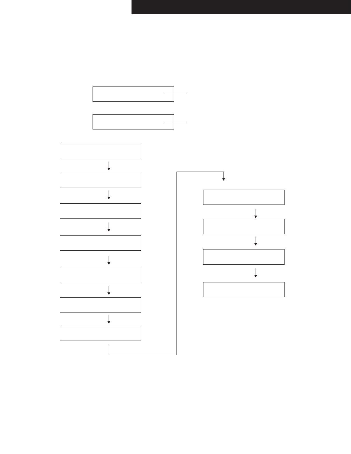
SERVICE INFORMATION MODE
Displaying Service information
This service information display system is helpful in analyze the status when the unit goes into Protect mode and is powered off.
Pay attention that the status will change if a button is pushed.
01:23 10h
e.g.
1. Press twice the ON/ STANDBY key while pressing the DISPLAY key.
Listening Mode Code List
- 80 F 27 DD
e.g.
Power off Cause
T : Thermal Protect
V : Voltage Protect
I : Current Protect
- : Other
Temperature
: xx F or xx C
Volume Level Listenning Mode
---> Refer to the code list below.
Time after Power on
xx : xx
Time after Initialize
xx hour
1.01/13515AE8 The version of main microprocessor is
displayed only for 3 seconds.
e.g.
C_LM_LAST01
C_LM_PURE02
C_LM_DIRECT03
C_LM_STEREO04
C_LM_MONO05
C_LM_SURR20
C_LM_THX_MUSIC50
C_LM_THX_GAME70
C_LM_THX_CINEMA90
C_LM_THX_U2GAMEA0
C_LM_THX_U2MUSICA8
C_LM_THX_U2CINEMAB0
C_LM_ASCF4
C_LM_FLASHF5
C_LM_DEBUGMODEF6
C_LM_FLASH2F7
C_LM_FLASH3F8
C_LM_FLASH4F9
C_LM_FLASH_CHECKFA
C_LM_RPG0D
C_LM_ACTION0E
C_LM_ROCKBAND0F
C_LM_SPORTS10
3. Press HOME button again. The following information are displayed.
2. Press HOME button within 3 seconds above.
C_LM_AUDYSSEYD0
C_LM_DTSSS48
C_LM_ORCHESTRA06
C_LM_UNPLUGGED07
C_LM_STUDIOMIX08
C_LM_TVLOGIC09
C_LM_ALLCHST0A
C_LM_FULLMONO0B
C_LM_TD0C
C_LM_TESTTONEF1
C_LM_TESTTHRF2
C_LM_TESTAUTOF3
Information Displayed (Record this Information)
4. Press ON/STANDBY button to exit the display of service information.
(Ref.: Press RETURN button to initialize the data in the service information.)
ProtectData CLR
Normal display

TX-NR1030/3030/ PR-SC5530/ DTR-60.6/70.6/ DHC-80.6
OPERATION CHECK-1
NOTATION ABOUT ENTERING TEST MODE BY PRESSING BUTTON
In this procedure, the following notations are used to simplify explanation of how to press button.
e.g.-1 [TV/CD] + [ON/STANDBY] → [BD/DVD]
This means "While holding down TV/CD button, press ON/STANDBY button then release both buttons and then press
BD/DVD button".
e.g.-2 [DISPLAY] + [ON/STANDBY] *2 → [DIMMER]
This means "While holding down DISPLAY button, press ON/STANDBY button twice then release both buttons and then press
DIMMER button".
INITIAL SETTING FOR SHIPPING
Initialization of memories.
Do the following operation.
Unplug the power cord from AVR after the FL tube displays "Clear" and AVR goes standby.
[CBL/SAT] + [ON/STANDBY]
CONFIRMATION OF F/W VERSION
to display MMPU version.
to display another F/W version.
<NOTE>
It cannot enter a test mode immediately after power supply ON, please press the Setup key.
1. [DISPLAY] + [ON/STANDBY]
Do the following operation.
2. [TONE+]
M1.03/14307ALN
e.g.
CONFIRMATION OF MAIN CHECKSUM
MAIN Checksum can be confirmed the following operation.
[DISPLAY] + [ON/STANDBY] * 2 → [MEMORY]
Temperature and output voltage can be confirmed the following operation.
CONFIRMATION OF OUTPUT VOLTAGE AND THERMAL SENSOR
[DISPLAY] + [ON/STANDBY] * 2 → [TONE]
e.g.
001 042 F:x S:H
Amplifier power
Supply voltage condition
H : High-B
L : Low-B
Temperature
of thermal sensor
Voltage
of VOLH port
FAN speed
x: Stop
L: Low speed
H: High speed
e.g.
>ONKYO@
Main:
1.05/14X07AM
DSP 1st/NET:
1.03/14X08AMA
DSP 2nd
1.01/14930AMA
Video:
1.01/14X06AM
VSP(KYOTOG2H):
1.01/14910AEO
OSD(Sparta):
1.00/14219AM
Rogue(TX)
1.02/14730A
Rogue(RX)
1.01/14730A
>Integra@
Main:
1.05/14X07AM
DSP 1st/NET:
1.03/14X08AMA
DSP 2nd
1.01/14930AMA
Video:
1.01/14X06AM
VSP(KYOTOG2H):
1.01/14910AEI
OSD(Sparta):
1.00/14219AM
Rogue(TX)
1.02/14730A
Rogue(RX)
1.01/14730A
VS100:
1.30.72.1
Main
DSP 1st/NET
DSP 2nd
HDMI/VIDEO
VSP
OSD
HDCP TX
HDCP RX
Main
DSP 1st/NET
DSP 2nd
HDMI/VIDEO
VSP
OSD
HDCP TX
HDCP RX
HDBase-T

TX-NR1030/3030/ PR-SC5530/ DTR-60.6/70.6/ DHC-80.6
OPERATION CHECK-2
Model Name Distination Number Writing Data
TX-NR1030 Dx 2000 2000 TX-NR1030 Dx NR1 0 3 0 Dx 2 0 0 0
TX-NR1030 xx 8000 8000 TX-NR1030 xx NR1 0 3 0 x x 8 0 0 0
TX-NR1030 JJ 4000 4000 TX-NR1030 JJ NR1 0 3 0 J J 4 0 0 0
DTR-60.6 Dx 2060 2060 DTR-60.6 Dx DTR606 Dx 2 06 0
DTR-60.6 xx 8060 8060 DTR-60.6 xx DTR606 x x 8060
DTR-60.6 JJ 4060 4060 DTR-60.6 JJ DTR606 J J 4060
TX-NR3030 Dx 2200 2200 TX-NR3030 Dx NR3 0 3 0 Dx 2 2 0 0
TX-NR3030 xx 8200 8200 TX-NR3030 xx NR3 0 3 0 x x 8 2 0 0
TX-NR3030 JJ 4200 4200 TX-NR3030 JJ NR3 0 3 0 J J 4 2 0 0
DTR-70.6 Dx 2260 2260 DTR-70.6 Dx DTR706 Dx 2 26 0
DTR-70.6 xx 8260 8260 DTR-70.6 xx DTR706 x x 8260
PR-SC5530 Dx 2400 2400 PR-SC5530 Dx SC5 5 30 Dx 2400
PR-SC5530 xx 8400 8400 PR-SC5530 xx SC5 5 3 0 x x 8 40 0
DHC-80.6 Dx 2460 2460 DHC-80.6 Dx DHC8 0 6 Dx 2 4 6 0
DHC-80.6 xx 8460 8460 DHC-80.6 xx DHC8 0 6 x x 8 4 6 0
DHC-80.6 JJ 4460 4460 DHC-80.6 JJ DHC8 0 6 J J 4 4 6 0
FL Display
1. Set the following VOL level.
3. Press the following button, while "TEST - " is displayed, then each test mode is set.
TEST MODE FOR OPERATION
Do the following operation.
2. [TV/CD] + [ON/STANDBY]
TEST-_
1-00
2-00
3-00
4-00
5-00
6-00
[BD/DVD]
[CBL/SAT]
[STB/DVR]
[GAME]
[PC]
[AUX]
KEY TEST
[MEMORY]
IDLING TIMER / Wi-Fi check
[TUNING MODE]
FL TEST
[DIMMER](RT/PTY/TP)
[ENTER] FIRMWARE COMBINATION CHECK
Button ButtonTest Mode Test Mode
In the test mode, (TONE)+ button is TEST MODE UP and (TONE)- button is TEST MODE DOWN.
TEST 1-00 → TEST 1-01 → TEST 1-02 - - - - TEST 2-00
e.g.
Model name and destination can be confirmed the following operation.
[TV/CD] + [ON/STANDBY] → [DIMMER](RT/PTY/TP) → [TONE+] *4
CONFIRMATION OF MODEL NAME AND DESTINATION
N R 1 0 3 0 D x 2 0 0 0
FL DIS Name Destination A B C D
A:Value of AD port of BAND
B:Value of AD port of INIT1
C:Value of AD port of INIT2
D:Value of AD port of INIT3
e.g.
IDLING TIMER (TEST 1-01)
This mode is used for aging for idling.
Once the following test mode is set, idling timer mode works.
Idling timer mode includes the following functions.
Test mode TEST 1-01
Function Timer
Voltage-detection protector check
F/W update route test
Wi-Fi connection check
Z2 DAC route check by playing USB flash device
WAV file L+Rch and Rch repetition (1sec each)
Once the above test mode is set, AVR's status changes to idling timer mode and voltage-detection protector check automatically begins.
If voltage-detection protector check is all OK, Wi-Fi connection check automatically begins.
Even if one channel of voltage-detection protector check is NG, Wi-Fi connection check doesn't begin.
Refer to CONFIRMATION OF VOLTAGE-DETECTION PROTECTORS (next page).
Refer to CONFIRMATION OF UPDATE ROUTE (next page).
Refer to CONFIRMATION OF Wi-Fi CONNECTION (next page).
Refer to CONFIRMATION OF ZONE2 DAC ROUTE (next page).
VOL level : 30
Button Test Mode
<NOTE> Store only one file (the above mentioned) into the USB flash device to avoid making trouble.

TX-NR1030/3030/ PR-SC5530/ DTR-60.6/70.6/ DHC-80.6
OPERATION CHECK-3
1N/A
2VIDEO-OSD
3 DA830 - KG2H
4VIDEO-HDCPTX
5VIDEO-HDCPRX
CONFIRMATION OF VOLTAGE-DETECTION PROTECTORS.(The following model only)
to the following test mode.
2. AVR automatically tests in the following test sequence. And if it is all OK, Wi-Fi test will begin.
3. If FL tube displays Wi-Fi check mode then voltage-detection protectors test will be completed.
TEST 1-01
Test sequence
<NOTE>
Don't connect load nor short speaker terminals.
1-2. [TV/CD] + [ON/STANDBY] → [BD/DVD]
1-1. set the volume level to 30
1. Do the following operation.
1-3. [TONE +]
CONFIRMATION OF UPDATE ROUTE.
2. Once the above mentioned test mode is entered, voltage-detection protectors function is checked automatically first, then update
route check will begin.
If the result of update route check is no problem then Wi-Fi check will begin. If the result is NG then NG message will be shown on
the FL tube.
3. If FL tube displays Wi-Fi check mode then voltage-detection protectors test and update route check are passed.
to the following test mode.
TEST 1-01
1-2. [TV/CD] + [ON/STANDBY] → [BD/DVD]
1-1. set the volume level to 30
1. Do the following operation.
1-3. [TONE +]
CONFIRMATION OF Wi-Fi CONNECTION (The following model only)
1. Setting Wi-Fi routers.
3. Once the above mentioned test mode is entered, voltage-detection protectors function is checked automatically first, then update
route check will begin and then Wi-Fi check will begin.
In Wi-Fi check mode, it connects an access point automatically. Wi-Fi LED flashes during connection.
4. If connection is completed and IP address is successfully acquired, Wi-Fi LED turning lights off and the value of RSSI to an access
point is displayed in dBm.
If the connection is failed, NG is displayed.
In case value of RSSI level isn't showed on the FL tube at all past 4 minutes in this timer mode, judge as NG.
If the connection is failed, exit the idling timer mode by pressing the TV/CD button and please try again from step-1.
TEST 1-01
2. set the following test mode.
02 -55d 01’ 14’’
RSSI(dbm)SSID No Time Counter
e.g.
CONFIRMATION OF ZONE2 DAC ROUTE
1. Connect USB memory or USB storage to AVR front USB port.
3. After being displayed Wi-Fi RSSI level, it will play back wave file from USB storage.
(DTR60.6/DTR-70.6/DHC80.6) After update route check, it will play back wave file from USB storage.)
4. Check the wave form that appears L+R and R alternately from the following output terminal.
Output terminal : ZONE2 PRE/LINE OUT
2. set the following test mode.
TEST 1-01
Detail of NG number of F/W update route test is as below.
Applied model TX-NR1030/3030, DTR-60.6/70.6
(FL+)→(FR-)→(C+)→(SL-)→(SR+)→(SBL-)→(SBR+)→(FWL-)→(FWR+)→(FHL-)→(FHR+)
Applied model TX-NR1030/3030,PR-SC5530

TX-NR1030/3030/ PR-SC5530/ DTR-60.6/70.6/ DHC-80.6
OPERATION CHECK-4
CONFIRMATION OF CURRENT DETECTION PROTECTORS (The following model only)
2. Confirm that relay is not cut off even if you connect the following load A to the following channels one by one.
3. Confirm that relay is cut if you connect the following load B to the following channels one by one.
Channel FL, FR, C, SL, SR, SBL, SBR, LH, RH, LW ,RW ch
Load A 3 ohm
Load B 1 ohm
to the following test mode.
TEST 1-09
1-2. [TV/CD] + [ON/STANDBY] → [CBL/SAT]
1-1. set the volume level to 30
1. Do the following operation.
1-3. [TONE - ]
CONFIRMATION OF OUTPUT SENSOR
After lighting "FM STEREO" on the FL tube.
Relays RL6901, RL6902, RL6903, RL6904
to the following test mode.
TEST 1-07 and TEST 1-08
1-2. [TV/CD] + [ON/STANDBY] → [CBL/SAT]
1-1. set the volume level to 30
1. Do the following operation.
1-3. [TONE - ] *2 and (*3)
CONFIRMATION OF KEY OPERATION
2. Confirm each key and master volume operation.
3. If "ON/STANDBY" button is pressed, AVR escapes from this KEY test mode.
Therefor, press the "ON/STANDBY" button, after checking other buttons finished.
to the following test mode.
TEST 1-06
1-2. [TV/CD] + [ON/STANDBY] → [CBL/SAT]
1-1. set the volume level to 30
1. Do the following operation.
1-3. [TONE - ] *4
CONFIRMATION OF NETWORK
1. Connect the receiver to the router.
3. Confirm that the AVR's display shows appropriate IP address.
Please wait for about 1 minute after turning on the AVR when using the following test mode.
Connection
Ethernet
cable
ETHERNET connector
to the following test mode.
TEST 1-05
2-2. [TV/CD] + [ON/STANDBY] → [CBL/SAT]
2-1. set the volume level to 30
2. Do the following operation.
2-3. [TONE - ] *5
CONFIRMATION OF COOLING FAN OPERATION
1. Confirm fan that is not rotating.
3. Set the following test mode B and confirm fan that is rotating at LOW speed.
2. Set the following test mode and confirm fan that is rotating at HIGH speed.
TEST 1-07
TEST 1-08
Applied model TX-NR1030/3030, DTR-60.6/70.6
LW ,RW ch : TX-NR3030, DTR-70.6 only
Applied model TX-NR1030/3030, DTR-60.6/70.6
Router

TX-NR1030/3030/ PR-SC5530/ DTR-60.6/70.6/ DHC-80.6
OPERATION CHECK-5
CONFIRMATION OF FL TUBE AND LED
1. Do the following operation.
2. Confirm that all LEDs and all segments of FL tube are lit.
[TV/CD] + [ON/STANDBY] → [DIMMER]
CONFIRMATION OF HEAD PHONE OPERATION
Confirm the headphone mark when headphones plug is inserted into the PHONES jack.
CONFIRMATION OF FM RADIO OPERATION
1. Setting of Signal Generator(SG)
Carrier frequency any
Modulation 1kHz
Deviation 75kHz
Output level 35dBu
2. Waveform confirmation
Set the signal of SG as following channels and confirm output is the following table.
SG Input Lch R ch
(1) R ch only No Yes
(2) L + R ch Yes Yes
3. Confirmation of Stereo indicator
Set SG as stereo and confirm stereo indicator is on.
4. Confirmation of Auto stop operation
Do auto tuning (Press TUNING UP or TUNING DOWN button) and confirm that the searching stops when a station that
is set by SG is found.
Output
CONFIRMATION OF RDS (RADIO DATA SYSTEM) OPERATION (Applied to MPP/MPB/MM* type )
1. Input 98MHz,30dBμ signal modulated with RDS data.
2. When a PS information is received, the name of the station "RDS TEST" shall be displayed within 2 seconds
instead of the frequency.
CONFIRMATION OF OSD(ON SCREEN DISPLAY) OPERATION
1. When HOME button is pushed, confirm that setup menu is displayed in HDMI Out.
2. Confirm that specified operations for ENTER(with 4-cursor) buttons are made.
CONFIRMATION OF CEC OPERATION
1. Connect AVR's HDMI OUT to HDMI input of appliance compatible with CEC(SINK or REPEATER) by HDMI cable.
2. Turn on the power to the AVR
FL tube will display "OK" or "NG".
to the following test mode.
TEST 6-00
3-2. [TV/CD] + [ON/STANDBY] → [AUX]
3-1. set the volume level to 30
3. Do the following operation.
1. Press TEST TONE on remote controller then press CH SELECT repeatedly.
Set turn to Dolby Test mode tone Check speaker condition.
2. Please check that a sound comes out from each channel.
-> FL ch -> C ch -> FR ch -> SR ch -> SBR ch -> SBL ch -> SL ch -> SW ch ->
CONFIRMATION OF DOLBY TEST TONE

TX-NR1030/3030/ PR-SC5530/ DTR-60.6/70.6/ DHC-80.6
OPERATION CHECK-6
CONFIRMATION OF VIDEO SIGNAL-DETECTION
2. Confirm the following indicator lights up on the FL TUBE when the following video signal is input.
3. Furthermore, confirm the following indicator is turned off on the FL TUBE when the following video signal isn't input at the
following test mode as well.
Input terminal
Indicator
(1) (2)
Composite
FM STEREO
Component
RDS
1-2. [TV/CD] + [ON/STANDBY] → [PC]
1-1. set the volume level to 25(TX-NR636, DTR-30.6) or 30(TX-NR737, 838, DTR-40, 50.5).
1. Do the following operation.
to the following test mode.
TEST 5-01
1-3. [TONE +]
Confirm Video output signal as shown Table 2, while Video signal are input as shown Table 1 in "Video in_out" sheet.
Table-1
Table-2
<NOTE>Confirm the HDMI path at 1080p signal.
CONFIRMATION OF VIDEO IN/OUT
CONFIRMATION OF FL DISPLAY
The contents of the step are as follows.
1. Lit all segment and LED
2. Lit '23456789ABCDEF' and LED.
3. Lit a even number segment and LED.
4. Lit an odd number segment and LED.
5. The Destination setting is displayed and LED..
1-2. [TV/CD] + [ON/STANDBY] → [DIMMER(RT/PTY/TP)]
1-1. set the volume level to 30
1. Do the following operation.
to the FL test mode
[TONE-] = Step down
[TONE+] = Step up
Component HDMI
BD/DVD --- IN1 E IN1 G
CBL/SAT A IN2 F IN2 H
STB/DVR B --- --- IN3 I
GAME C --- --- IN4 J
--- --- --- --- IN5 K
--- --- --- --- IN6 L
--- --- --- --- IN7 ---
AUX D --- --- AUX M
Video Signal -> Composite Video
Output
Test mode Zone2 out MONITOR
OUT
5-00(BD/DVD) --- ---
5-01(CBL/SAT) A A
5-02(STB/DVR) *B B
5-03(GAME) *C C
5-04(PC) --- ---
5-05(IN6) --- ---
5-06(IN7) --- ---
5-07(AUX) *D D
5-08(BD/DVD) --- ---
5-09(CBL/SAT) *A *A
OUT Main/Sub/Zone2OUT
EG
FH
Composite Video Component HDMI
--- K
--- L
--- I
--- J
*E E
*F A
--- ---
--- ---

TX-NR1030/3030/ PR-SC5530/ DTR-60.6/70.6/ DHC-80.6
OPERATION CHECK-7
TEST DSP DSP DSP Config. Master Vol. Speaker 12V etc.
No Output Output Output SW/F/C/S/SB /Zone2 Vol. Relay TRG
ch Frequency Voltage /H/W
1-00 SELECTOR MUTING TIME REDUCTION MODE - - - Y/L/L/L/L/L/L 82 (0dB) F - Analog Input Only
1-01 IDLING TIMER Timer start - - - Y/L/L/L/L/L/L Min (-82dB) F IDLING TIMER
V Protect (FL) FL +DC +Max Y/L/L/L/L/L/L Max (+18dB) F/CS/SB/H/W - *1, *3 +DC Protect
V Protect (FR) FR -DC -Max Y/L/L/L/L/L/L Max (+18dB) F/CS/SB/H/W - *1, *3 -DC Protect
V Protect (C) C +DC +Max Y/L/L/L/L/L/L Max (+18dB) F/CS/SB/H/W - *1, *3 +DC Protect
V Protect (SL) SL -DC -Max Y/L/L/L/L/L/L Max (+18dB) F/CS/SB/H/W - *1, *3 -DC Protect
V Protect (SR) SR +DC +Max Y/L/L/L/L/L/L Max (+18dB) F/CS/SB/H/W - *1, *3 +DC Protect
V Protect (SBL) SBL -DC -Max Y/L/L/L/L/L/L Max (+18dB) F/CS/SB/H/W - *1, *3 -DC Protect
V Protect (SBR) SBR +DC +Max Y/L/L/L/L/L/L Max (+18dB) F/CS/SB/H/W - *1, *3 +DC Protect
V Protect (FHL) FHL -DC -Max Y/L/L/L/L/L/L Max (+18dB) F/CS/SB/H/W - *1, *3 -DC Protect
V Protect (FHR) FHR +DC +Max Y/L/L/L/L/L/L Max (+18dB) F/CS/SB/H/W - *1, *3 +DC Protect
V Protect (FWL) FWL -DC -Max Y/L/L/L/L/L/L Max (+18dB) F/CS/SB/H/W - *1, *3 -DC Protect
V Protect (FWR) FWR +DC +Max Y/L/L/L/L/L/L Max (+18dB) F/CS/SB/H/W - *1, *3 +DC Protect
UPDATE ROUTE - - - Y/L/L/L/L Min (-82dB) F - UPDATE ROUT CHECK
Wi-Fi check - - - Y/L/L/L/L Min (-82dB) F - Wi-Fi check
Z2 DAC (USB Play) - - - Y/L/L/L/L Min (-82dB) F - Z2 PREOUT Z2 DAC (USB Play)
1-02 MULTI TONE 1kHz + 30Hz + 20kHz , -20dBFS ALL 1kHz+30Hz+20kHz -20dBFS Y/L/L/L/L/L/L 82 (0dB) F/CS/SB/H/W - *6 Multi tone
1-03 Wi-Fi check - - - Y/L/L/L/L Min (-82dB) F - Wi-Fi check
1-04 UPDATE ROUTE - - - Y/L/L/L/L Min (-82dB) - - UPDATE ROUT CHECK
1-05 DISPLAY IP ADDRESS - - - Y/L/L/L/L Min (-82dB) - - IP ADDRESS
1-06 KEY TEST - - - Y/L/L/L/L 76(-6dB) F/C/SB - *7 KEY TEST
1-07 VOLH DET / FAN HIGH-SPEED / 12V TRIGGER C F,C,S,SB,H 1kHz 0dBFS Y/L/L/L/L/L/L 84 (+2dB) F/CS/SB/H/W C*5 VOLHDET䚸FAN High
1-08 VOLH DET / FAN LOW-SPEED / 12V TRIGGER B (ZONE3) W,C,S,SB,H 1kHz 0dBFS Y/L/L/L/L/L/L 84 (+2dB) F/CS/SB/H/W B (Z3) *5 VOLH DET䚸FAN Low
1-09 CURRENT PROTECT / 12V TRIGGER A (ZONE2) ALL Pulse Max Y/L/L/L/L/L/L 78(-4dB) F/CS/SB/H/W A (Z2) *1, *4 Current Protect
TEST Analog Input Listening Mode/ VIDEO Compo- HDMI 12V Digital Input Config. Master Vol. Speaker etc.
No [Rec Sel] Input Format Input nent V TRG /Output Zone2/3 Vol. Relay
(Zone2/Zone3)
2-00 BD/DVD (Off) Analog All Ch Stereo BD/DVD IN1 - - - - Max (+18dB)
F/CS/SB/H/W(11ch model䠅
F/CS/SB/H(9ch model㸧
LINE GAIN,HUM NOISE
2-01 BD/DVD (Off) ADC DSP 13ch Thru. BD/DVD IN1 - - - Y/L/L/L/L/L/L 82 (0dB)
F/CS/SB/H/W(11ch model䠅
F/CS/SB/H(9ch model䠅
ADC GAIN etc.
2-02 BD/DVD (Off) ADC DSP 13ch Thru. BD/DVD IN1 - - - Y/L/L/L/L/L/L Min (-82dB)
F/CS/SB/H/W(11ch model䠅
F/CS/SB/H(9ch model䠅
MIN NOISE
2-03 CBL/SAT (Off) DIR DSP 13ch Thru CBL/SAT - - - *OPT1 Y/L/L/L/L/L/L Max (+18dB)
F/CS/SB/H/W(11ch model䠅
F/CS/SB/H(9ch model䠅
AMUT OFF DAC HUM NOISE
2-04 MIC ADC DSP 13ch Thru. BD/DVD BD/DVD - - - Y/L/L/L/L/L/L Max (+18dB)
F/CS/SB/H/W(11ch model䠅
F/CS/SB/H(9ch model䠅
MIC GAIN
2-05 MIC ADC DSP 13ch Thru. BD/DVD BD/DVD - - - Y/L/L/L/L/L/L Max (+18dB)
F/CS/SB/H/W(11ch model䠅
F/CS/SB/H(9ch model䠅
MICMUTE ON MIC MUTING
2-06 PHONO/Source Direct BD/DVD - - - - - Max (+18dB) F PHONO GAIN etc.
2-07 BD/Source Bi AMP BD/DVD IN1 - - - - Max (+18dB) F/C/S/FH Bi AMP
2-08 BD/Source ADC DSP 13ch Thru. BD/DVD IN1 -- - Y/L/L/L/L/L/L Max (+18dB)
F/CS/SB/H/W(11ch model䠅
F/CS/SB/H(9ch model䠅
HUM NOISE
2-09 BD/Source ADC DSP 5ch Thru. BD/DVD IN1 - - - Y/L/L/L Max (+18dB) F/C/S DIFF SIG MODE
2-10 BD䠄BALANCE䠅Direct BD/DVD IN1 -- - Y/L/L/L/L/L/L Max (+18dB) F/CS/SB/H/W BALANCE
2-11 BD䠄BALANCE䠅ADC DSP 13ch Thru. BD/DVD IN1 - - - Y/L/L/L/L/L/L Max (+18dB) F/CS/SB/H/W BALANCE:MONO
2-12 BD/DVD (Off) ADC DSP 13ch Thru. BD/DVD IN1 - - - Y/L/L/L/L Max (+18dB) CS/SB SPRLF OFF PREOUT RELAY OFF
2-13 BD/DVD (Off) Stereo(Direct) BD/DVD IN1 - - - - Max (+18dB) F SW=NO HP GAIN/SP-B GAIN
2-14 PHONO/Source Direct BD/DVD - - - - - 62(-20dB) F PHONO SEP.
2-15 BD/DVD (Off) Analog All Ch Stereo BD/DVD IN1 - - - Y/L/L/L/L/L/L Max (+18dB) F/CS/SB/W HighAMP->Widech path
2-16 BD/DVD (Off) Analog All Ch Stereo BD/DVD IN1 - - - Y/L/L/L/L/L/L Max (+18dB) F/CS/H/W SBAMP->Widech path
3-00 FM/Source Stereo(Direct) BD/DVD BD/DVD - - - - 84(+2dB) F
3-01 GAME(BD/TV) Stereo(Direct) BD/DVD BD/DVD - - - - Max (max) F/Z2/Z3 LINE/PRE:PRE Powered:ON䚸
Z2/Z3Vol=82
3-02 GAME(BD/TV) Stereo(Direct) BD/DVD BD/DVD - - - - Max (max) F/Z2/Z3 Z2MUTE ON
LINE/PRE:PRE
Powered:ON䚸
Z2/Z3Vol=82
3-03 GAME(BD/TV) Stereo(Direct) BD/DVD BD/DVD - - - - Max (max) F/Z2/Z3 Powered:ON
LINE/PRE:PRE
Z2/Z3Vol=82
Z2 Bass=Max
3-04 GAME(BD/TV) Stereo(Direct) BD/DVD BD/DVD - - - - Max (max) F/Z2/Z3 Powered:ON
LINE/PRE:PRE
Z2/Z3Vol=82
Z2 Bass=Min
3-05 GAME(BD/TV) Stereo(Direct) BD/DVD BD/DVD - - - - Max (max) F/Z2/Z3 Powered:ON
LINE/PRE:PRE
Z2/Z3Vol=82
Z2 Treble=Max
3-06 GAME(BD/TV) Stereo(Direct) BD/DVD BD/DVD - - - - Max(max) F/Z2/Z3 Powered:ON
LINE/PRE:PRE
Z2/Z3Vol=82
Z2 Treble=Min
3-07 GAME(BD/TV) Stereo(Direct) BD/DVD - - - - - Min (-82dB) F/Z2/Z3 Z2/Z3PRE VOL MAX ATT
3-08 GAME(BD/TV) Stereo(Direct) BD/DVD - - - - - Max (FIX) F/Z2/Z3 Z2/Z3 LINEOUT (Mid)
3-09 USB/(Source) Stereo(Direct) Last - - - Front USB - Min (-20dB) FZ2 out 1.44.1kHz_16bit_1kHz_0
dBfs_L&R.wav *2
3-10 USB/(Source) Stereo(Direct) Last - - - Front USB - Min (-20dB) FZ2 out 2.44.1kHz_16bit_-∞
dBfs_L&R.wav *2
3-11 USB/(Source) Stereo(Direct) Last - - - Front USB - Min (-20dB) FZ2 out 3.44.1kHz_16bit_20Hz_0
dBfs_L&R.wav *2
3-12 USB/(Source) Stereo(Direct) Last - - - Front USB - Min (-20dB) FZ2 out 4.44.1kHz_16bit_20kHz_
0dBfs_L&R.wav *2
3-13 USB/(Source) Stereo(Direct) Last - - - Front USB - Min (-20dB) FZ2 out 5.44.1kHz_16bit_1kHz_0
dBfs_Lch.wav *2
3-14 USB/(Source) Stereo(Direct) Last - - - Front USB - Min (-20dB) FZ2 out 6.44.1kHz_16bit_1kHz_0
dBfs_Rch.wav *2
3-15 USB/(Source) DSD DAC Direct Last - - 51 F/C/S - DSD(NET) DAC Direct check

TX-NR1030/3030/ PR-SC5530/ DTR-60.6/70.6/ DHC-80.6
OPERATION CHECK-8
<NOTE>
TEST of NET/USB can't do immediately after the start-up.It should be measure after other TEST.
DSP Output channel DSP DSP Config. Master Speaker etc.
No. Output Output Vol. Relay
Frequency Voltage
4-00 ALL
1kHz (SW㻦30Hz)
-20dBFS Y/L/L/L/L/L/L 82 (0dB) F/CS/SB/H/W *6
4-01 ALL
30Hz (SW㻦1kHz)
-20dBFS Y/L/L/L/L/L/L 82 (0dB) F/CS/SB/H/W *6
4-02 ALL 20kHz -20dBFS Y/L/L/L/L/L/L 82 (0dB) F/CS/SB/H/W *6 DSP Freq.Response
4-03 SW 30Hz -20dBFS Y/L/L/L/L/L/L 72(-10dB) F/CS/SB/H/W *6 Characteristic(1)
4-04 FL,FR 30Hz -20dBFS Y/L/L/L/L/L/L 82 (0dB) F/CS/SB/H/W *6 Characteristic(2)
4-05 ALL
1kHz (SW㻦30Hz)
-20dBFS Y/L/L/L/L/L/L 82 (0dB) F/CS/SB/H/W Mute On *6 Muting
4-06 ALL
1kHz (SW㻦30Hz)
-20dBFS Y/L/L/L/L/L/L
Min.(-∞dB)
F/CS/SB/H/W *6 Volume Max.Attenuation
4-07 FR,C,SUR,SURB,HIGH,WIDE,SW 10kHz -20dBFS Y/L/L/L/L/L/L 82 (0dB) F/CS/SB/H/W Mute:FL *6 Separation(FL)
4-08 FL,C,SUR,SURB,HIGH,WIDE,SW 10kHz -20dBFS Y/L/L/L/L/L/L 82 (0dB) F/CS/SB/H/W Mute:FR *6 Separation(FR)
4-09 F,SUR,SURB,HIGH,WIDE,SW 10kHz -20dBFS Y/L/L/L/L/L/L 82 (0dB) F/CS/SB/H/W Mute:C *6 Separation(C)
4-10 F,C,SR,SURB,HIGH,WIDE,SW 10kHz -20dBFS Y/L/L/L/L/L/L 82 (0dB) F/CS/SB/H/W Mute:SL *6 Separation(SL)
4-11 F,C,SL,SURB,HIGH,WIDE,SW 10kHz -20dBFS Y/L/L/L/L/L/L 82 (0dB) F/CS/SB/H/W Mute:SR *6 Separation(SR)
4-12 F,C,SUR,SBR,HIGH,WIDE,SW 10kHz -20dBFS Y/L/L/L/L/L/L 82 (0dB) F/CS/SB/H/W Mute:SBL *6 Separation(SBL)
4-13 F,C,SUR,SBL,HIGH,WIDE,SW 10kHz -20dBFS Y/L/L/L/L/L/L 82 (0dB) F/CS/SB/H/W Mute:SBR *6 Separation(SBR)
4-14 F,C,SUR,SURB,HIGH,WIDE,SW2 30Hz -20dBFS Y/L/L/L/L/L/L 82 (0dB) F/CS/SB/H/W Mute:SW1 *6 Separation(SW1)
4-15 F,C,SUR,SBR,HR,WIDE,SW 10kHz -20dBFS Y/L/L/L/L/L/L 82 (0dB) F/CS/SB/H/W Mute:LH *6 Separation(FHL)
4-16 F,C,SUR,SBR,HL,WIDE,SW 10kHz -20dBFS Y/L/L/L/L/L/L 82 (0dB) F/CS/SB/H/W Mute:RH *6 Separation(FHR)
4-17 F,C,SUR,SRB,HIGH,RW,SW 10kHz -20dBFS Y/L/L/L/L/L/L 82 (0dB) F/CS/SB/H/W Mute:LW *6 Separation(FWL)
4-18 F,C,SUR,SRB,HIGH,LW,SW 10kHz -20dBFS Y/L/L/L/L/L/L 82 (0dB) F/CS/SB/H/W Mute:RW *6 Separation(FWR)
4-19 FL +DC +Max Y/L/L/L/L/L/L Max(Max) F/CS/SB/H/W *1,*3 +DC Protect(FL)
4-20 FR -DC -Max Y/L/L/L/L/L/L Max(Max) F/CS/SB/H/W *1,*3 -DC Protect(FR)
4-21 C +DC +Max Y/L/L/L/L/L/L Max(Max) F/CS/SB/H/W *1,*3 +DC Protect(C)
4-22 SL -DC -Max Y/L/L/L/L/L/L Max(Max) F/CS/SB/H/W *1,*3 -DC Protect(SL)
4-23 SR +DC +Max Y/L/L/L/L/L/L Max(Max) F/CS/SB/H/W *1,*3 +DC Protect(SR)
4-24 SBL -DC -Max Y/L/L/L/L/L/L Max(Max) F/CS/SB/H/W *1,*3 -DC Protect(SBL)
4-25 SBR +DC +Max Y/L/L/L/L/L/L Max(Max) F/CS/SB/H/W *1,*3 +DC Protect(SBR)
4-26 FWL -DC -Max Y/L/L/L/L/L/L Max(Max) F/CS/SB/H/W *1,*3,*7 -DC Protect(FWL)
4-27 FWR +DC +Max Y/L/L/L/L/L/L Max(Max) F/CS/SB/H/W *1,*3,*7 +DC Protect(FWR)
4-28 FHL -DC -Max Y/L/L/L/L/L/L Max(Max) F/CS/SB/H/W *1,*3 -DC Protect(FHL)
4-29 FHR +DC +Max Y/L/L/L/L/L/L Max(Max) F/CS/SB/H/W *1,*3 +DC Protect(FHR)
4-30 ALL 30Hz -20dBFS Y/L/L/L/L/L/L 82 (0dB) F/CS/SB/H/W PASSIVE SW=ON PASSIVE SW
4-31 F,C,SUR,SURB,HIGH,WIDE,SW1 30Hz -20dBFS Y/L/L/L/L/L/L 82 (0dB) F/CS/SB/H/W Mute:SW2 *6 Separation(SW2)
DSP Gain
DSP Freq.Response
*1. All SP-RELAYs are turned ON only at the time of this STEP.
Moreover, whether make RELAY restoration time at the time of protection operation into 1 second, and PROTECT input "H" is detected
how many times or it continues 1 second or more, RELAY is not held at OFF or POWER OFF is not carried out, either.
When "H" is 1 seconds or more to PROTECT input and it is set to "L", RELAY is turned ON again.
Moreover, not any MUTE is outputted at the time of this STEP.
*2. Use USB memory which stored only following signals.
In addition, measure using application.
1.44.1kHz_16bit_1kHz_0dBfs_L&R.wav Reference
2.44.1kHz_16bit_-∞dBfs_L&R.wav SN ratio
3.44.1kHz_16bit_20Hz_0dBfs_L&R.wav Freq. resp.
4.44.1kHz_16bit_20kHz_0dBfs_L&R.wav Freq. resp.
5.44.1kHz_16bit_1kHz_0dBfs_Lch.wav Separation
6.44.1kHz_16bit_1kHz_0dBfs_Rch.wav Separation
7.48kHz_16bit_1kHz_0dBfs_L&R.wav Operation check
*3. If voltage-detection protector check in TEST-1-01 starts, DC voltage is output immediately from each channel. (within 100msec.)
2mS
20mS
2mS
MAX
-MAX
*4. The following signal is output from all channel continuously in TEST1-09.
Auto Measurement Mode
*5. VOLH is detected and H/L of SEC1H is changed.
A detection level is the same as the normal mode. When it is detected, light "FM STEREO" on FL TUBE.
*7. In skip test for 9channel POWER AMP set

TX-NR1030/3030/ PR-SC5530/ DTR-60.6/70.6/ DHC-80.6
OPERATION CHECK-9
[NOTES]
1. DSP Thru of Listening Mode outputs L Input signal to L/C/SL/SBL, and outputs R Input signal to R/SR/SBR/SW.
2. Config. is in order of SW/Front/Center/Surround/Surround back.
3. Mute is function to stop output(from the channel) by using inner DSP programming.
4. When Listening Mode is DSP thru, an analog SW is changed into the state of SURROUND.
5. At the time of PRTCTTHM detection, it is displayed on FLT as "THERMAL PROTECT".
6. In all test modes, it is not concerned with detection of VOLH but SEC1H are made "H" fixation. (Except TEST 1-07 and 1-08.)
Following frequencies are automatically written in the preset memory, when the unit goes into "TEST 3-00".
TEST-3-00
Input selector DIGITAL COMPO- Volume HDMI
INPUT NENT
5-00 BD/DVD HDMI IN1 51 IN1 DISC-D(BD) Tr.20or28
5-01 CBL/SAT HDMI IN2 51 IN2 DISC-D(BD) Tr.21
5-02 STB/DVR HDMI - 51 IN3 DISC-D(BD) Tr.21 or A(DVD)
5-03 GAME HDMI - 51 IN4 DISC-D(BD) Tr.21 or A(DVD)
5-04 PC HDMI - 51 IN5 DISC-D(BD) Tr.21 or A(DVD)
5-05 IN6 HDMI - 51 IN6 DISC-D(BD) Tr.21 or A(DVD)
5-06 IN7 HDMI - 51 IN7 DISC-D(BD) Tr.21 or A(DVD)
IN8 HDMI - 51 IN8 DISC-D(BD) Tr.21 or A(DVD)
5-07 AUX HDMI - 51 AUX Through(Main/Sub:Both), SPDIF DISC-D(BD) Tr.21 or A(DVD)
5-08 BD/DVD - IN1 MIN - -
5-09 CBL/SAT - - MIN - -
BD/DVD - - MIN - CV > CV, COMPONENT
5-10 PC(RGB) - - MIN - RGB INPUT > HDMI OUT
5-11 PC/GAME HDMI - 51 IN5/IN4
6-00 BD/DVD HDMI IN1 60 IN3 DISC-C(SACD) TRACK12
6-01 BD/DVD COAX1* IN1 MIN - -
6-02 CBL/SAT HDMI ARC IN2 40/60 - -
6-03 BD/DVD HDMI - 51 IN1 -
6-04 BD/DVD HDMI - 51 IN1 -
6-05 BD/DVD HDMI - 51 IN1 -
6-06 CBL/SAT HDMI - 51 IN2 -
6-07 STB/DVR HDMI - 51 IN3 DISC-C(SACD) TRACK12
MHL Check(CABLE DET)
MHL Check(VBUS=ON)
MHL Check(VBUS=OFF)
Through(Main/Sub:Both), I2S
Through(Main/Sub:Both), SPDIF
HDMI DSD SIGNAL
CV (IN1)> HDMI(Main/Sub:Both)
Audio TV OUT = ON, VOL=0
HDMI AUDIO RETURN CHANNEL
Through(Main/Sub:Both), SPDIF
COMPONENT>HDMI(Main/Sub:Both)
Through(Main/Sub:Both)
Z2 HDMI TEST / HDMI Powered Z2
Audio out TV = ON
Audio out TV = ON
HDMI OUT is blue back
Audio out TV = ON
Audio out TV = ON
OUTPUT CH =
Audio out TV = ON
DSD(HDMI) DAC Direct check
CEC Z2relay Check
Through(Main/Sub:Both), SPDIF
MODE Reference TEST DISC*etc.
SP ALLch & SW-PO
SP ALLch & SW-PO
Audio out TV = ON
Audio out TV = ON
Video & HDMI Test mode
PRESET No. MD* MP*,MG* MJJ
MW*(10k) MW*(9k)
1 89.9MHz 89.90MHz 89.90MHz 76.0MHz
2 97.9MHz 97.90MHz 97.90MHz 82.0MHz
3 98.9MHz 98.90MHz 98.90MHz 83.0MHz
4 107.1MHz 107.10MHz 107.10MHz 84.0MHz
FM 5 107.9MHz 107.90MHz 107.90MHz 90.0MHz
6 100.1MHz 100.10MHz 100.10MHz 80.0MHz
7 88.1MHz 88.10MHz 88.10MHz 85.1MHz
8 104.1MHz 104.10MHz 104.10MHz 88.1MHz
9 95.3MHz 95.30MHz 95.30MHz 76.0MHz
10 106.7MHz 106.70MHz 106.70MHz 90.0MHz
11 530KHz 530KHz 522KHz 522kHz
12 630KHz 630KHz 630KHz 630kHz
13 990KHz 990KHz 990KHz 990kHz
14 1440KHz 1440KHz 1440KHz 1440kHz
AM 15 1710KHz 1710KHz 1611KHz 1611kHz
16 670KHz 670KHz 666KHz 666kHz
17 830KHz 830KHz 828KHz 828kHz
18 1310KHz 1310KHz 1314KHz 1314kHz
19 1200KHz 1200KHz 1197KHz 1197kHz
20 530KHz 530KHz 522KHz 522kHz
21 87.5MHz 87.50MHz 87.50MHz 76.0MHz
FM 22 107.9MHz 108.00MHz 108.00MHz 90.0MHz
23 103.7MHz 104.00MHz 104.00MHz 79.8MHz
24 104.5MHz 104.20MHz 104.20MHz 80.2MHz
AM 25 1180kHz 1180kHz 1179kHz 1179kHz
26 1220kHz 1220kHz 1215kHz 1215kHz

TX-NR1030/3030/ PR-SC5530/ DTR-60.6/70.6/ DHC-80.6
OPERATION CHECK-10
COOLING FAN(The following model only)
Circuit
FANCTRL
3
139
VOLH
Thermal sensor
137
Power amp.
COOLING FAN
Q6592
THERMAL1
Q6980
VOLH(Voltage of VOLH port)
THERMAL
(Temparature of
thermal sensor)
Q7011
MPU
(Main Microprocessor)
Normal/ Bi-Amp Powerd Zone-2,3,4
STOP
OFF or
Headphone
OFF or
Headphone
LOW MID LOW MID
HIGH HIGH
OFF
LOW
HIGH
MID
MID
LOW
LOW
STOP
LOWLOW
STOP STOP STOPSTOP STOP STOP
HIGH
LOW LOW LOW LOW LOW
MID MID MIDMID MID MIDMID
HIGH HIGH HIGH HIGHHIGHHIGH
THERMAL
-30 45 50 52 55 65 90 100
Shut down
immediately
Shut down
immediately
Shut down in
10 minutes
continuously
HIGH
MID
LOW
OFF
Hysteresis control
VOLH
0.35V 0.4V 1.9V 2.0V 2.2V 2.3V 3.3V
HIGH
MID
LOW
OFF
Hysteresis control
Value D/A output of the MPU
OFF
LOW
MID
HIGH
0V
1.7V
2.2V
3.3V
Condition to operate
How to check
1. How to check operation of Cooling Fan.
See “CONFIRMATION OF COOLING FAN OPERATION” in OPERATION CHECK-4.
2. How to check the value of THERMAL and VOLH.
See “CONFIRMATION OF OUTPUT VOLTAGE AND THERMAL SENSOR” in OPERATION CHECK-1.
0V
e.g.(TX-NR1030)
63
THERMAL2
Q6981 138
Q6951
Fan drive
Applied model TX-NR1030/3030, DTR-60.6/70.6
This manual suits for next models
1
Table of contents
Other Onkyo Receiver manuals

Onkyo
Onkyo TX-SR503E User manual

Onkyo
Onkyo TX-NR737 Installation guide

Onkyo
Onkyo TX-SR606 User manual

Onkyo
Onkyo HT-R590 User manual

Onkyo
Onkyo TX-NR1008 Specification sheet

Onkyo
Onkyo TX-8150 User manual

Onkyo
Onkyo TX-NR616 User manual

Onkyo
Onkyo HT-R320 User manual

Onkyo
Onkyo TX-NR900E User manual

Onkyo
Onkyo DR-90 User manual

Onkyo
Onkyo TX-SR706 - AV Receiver Manual

Onkyo
Onkyo HT-R550 User manual

Onkyo
Onkyo TX-SR702 User manual

Onkyo
Onkyo TX-NR809 User manual

Onkyo
Onkyo TXSR705S User manual

Onkyo
Onkyo TX-NR1007 User manual

Onkyo
Onkyo TX SR875 - AV Receiver User manual

Onkyo
Onkyo TX-SR573 User manual

Onkyo
Onkyo TX-NR414 User manual

Onkyo
Onkyo TX-NR900 User manual