Online UPS Specialist OPP Series User manual

- 1 - Revision 1.0
Operating Manual
OPP Series On-Line UPS

- 2 - Revision 1.0
Introduction
This user manual has been written to provide basic information
about the OPP UPS.
It will describe the key features of the UPS, as well as detail
referring to unpacking and installation, operation & configuration
and troubleshooting. It also includes a section on software
installation and general connectivity.
The specification section outlines all of the detailed parameters
of operation of the OPP UPS and provides general information
on approvals and certification.
The UPS should be installed according to the instructions in this
manual. Failure to do so could result in safety issues. It could
also invalidate your warranty.

- 3 - Revision 1.0
Safety Information
Please retain this user manual in close proximity of the UPS
for future reference.
Since the UPS unit operates from mains power and contains a
number of high current back-up batteries, the information in this
chapter is important to all personnel involved. Please take the
time to read this section before unpacking, installation and
operation of this UPS.
Storage and transportation
Because of the high energy stored within the batteries, the UPS
equipment must be handled with due care and attention. The
UPS must always be kept in the position marked on the external
packaging and must not be dropped.
Installation
Do not operate the equipment in the presence of flammable
gases or fumes. Operation of any electrical equipment in such
an environment constitutes a safety hazard. Do not place the
UPS in an unventilated room or enclosure.
The UPS must be installed in accordance to the instructions
within this manual. Failure to recognise the electrical hazards
could prove fatal.
Do not remove or unplug the input cord when the UPS is turned
on. This removes the safety ground from the UPS and the
equipment connected to the UPS.
Do not open the UPS cabinet. Some components inside the
UPS cabinet carry high voltage. To touch them may prove fatal.
All operations inside the UPS must be carried out by an
authorised service engineer from the manufacturer or agent
authorised by the manufacturer.

- 4 - Revision 1.0
Batteries
Once batteries have reached the end of their life, ensure they
are disposed of properly. Refer to your local codes for disposal
requirements.
Never dispose of batteries in a fire. Batteries may explode when
exposed to flame.
Replace batteries with the same number and type of batteries or
battery packs as originally installed in the equipment.

- 5 - Revision 1.0
Contents
1. General Description......................7
1.1. Basic functions of UPS ....................................... 7
1.2. General technical overview ................................ 7
1.3. Key features of the OPP..................................... 9
2. Storage and Unpacking..............11
2.1. Boxes supplied ................................................. 11
2.2. What’s in the box(es)........................................ 12
3. Installation and Set-up ...............14
3.1. Environment & positioning................................ 14
3.2. Free-standing configuration.............................. 14
3.3. Rack-mount configuration................................. 16
3.4. Rear panel features .......................................... 17
3.5. Power connection OPP1000 & OPP1500......... 18
3.6. Power connection OPP2500 & OPP3000......... 19
3.7. Power connection OPP4000 ~ OPP6000 ......... 21
3.8. Communication connectivity............................. 23
3.9. RS232 .............................................................. 24
3.10. REPO……………………………………………..26
4. Operation .....................................28
4.1. Description of front panel features.................... 28
4.2. Starting/shutting down the UPS & Bypass........ 29
4.3. Using the front panel ........................................ 31
4.4. Audible Alarms ................................................. 35
4.5. On mains operation .......................................... 36
4.6. On battery operation......................................... 37

- 6 - Revision 1.0
Contents
5. Trouble shooting.........................38
5.1. Basic trouble shooting guide ............................ 38
5.2. LCD trouble shooting guide .............................. 40
5.3. Replacing batteries........................................... 42
6. Software set-up ...........................44
6.1. General windows software installation.............. 44
7. Specification................................48
7.1. General specification ....................................... 48
7.2. Run time chart ................................................. 50
7.3. Fixing centres & dimension tables ................... 52

- 7 - Revision 1.0
1. General Description
1.1. Basic function of the UPS
An Uninterruptible Power Supply is designed to provide a
battery based source of AC power, such that under mains fail
conditions the load can be supported for a specified period of
time.
This time is generally dictated by the period required to
shutdown equipment in an orderly fashion, generator-starting
time or for an engineer to attend site. In a high percentage of
cases, utility failure is often less than 5 minutes.
This period is often only a “bridge” between mains fail and
generator starting.
1.2. General technical overview
Under normal conditions mains is fed into the rectifier which
provides DC power to the Inverter and DC (via the charger) to
charge the batteries. The inverter then feeds the load
continuously. If the primary mains supply fails, the UPS simply
uses the secondary supply (if connected) thus maintaining
power to the load without using it’s batteries.
If the auxiliary and primary supply fail, then the UPS continues
to supply the load via the inverter but the inverter now takes its
power from batteries (via the boost converter) not the rectifier.
The load therefore sees no change. The static switch or auto
bypass provides a fail-safe mechanism in UPS overload or UPS
fault conditions of Inverter fail, rectifier fail & battery failure.
This On-line topology of UPS provides a true sinewave output.

- 8 - Revision 1.0
General Description
1.2. General description – OPP Block
Diagram

- 9 - Revision 1.0
General Description
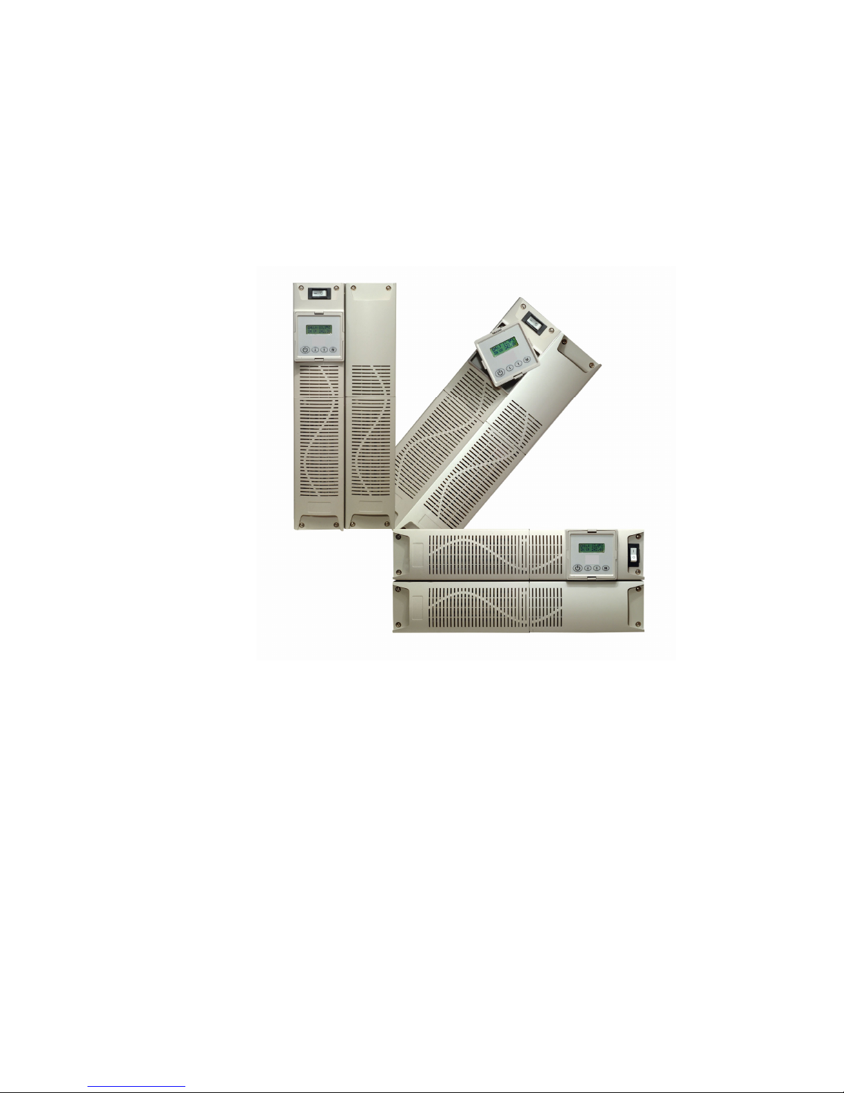
1.3. Key Features of the OPP1000 to
OPP6000
Self configuring battery pack. All UPS’ utilise batteries and,
depending on the power rating of the UPS, the internal DC
“string” voltage will be different: the higher the voltage, the lower
the current needs to be in order to deliver the same power and
consequently the UPS is less bulky and more efficient. To
optimise efficiency, the higher the kVA rating of the UPS, the
higher the “string” voltage used.
In the OPP design, the battery pack is configured in multiples to
achieve the required string voltages at higher kVA ratings.
The advantage of this is:
1. The right battery packs are always available.
2. The blocks are “plug and play” so installation is very fast.
3. Technical installations people are not needed to
install/change the batteries
4. The packs are small enough that they are considered a
“one man lift” so shipping & installation is much easier.
Dual mains input. Most UPS’ have one mains input, however
the OPP has 2. It is common for comms rooms to be fed from 2
supplies (possibly 2 phases of the same supply) so that if there
is a problem on one supply the other can take over and prevent
the UPS from needing to discharge its batteries until there is no
other option. In order to do this, ordinarily, a static switch is
required which selects “Mains 1” or “Mains 2” as the input to the
UPS depending upon which is available. Since OPP has 2
mains inlets, it is not necessary to have a static switch.
The advantages of this are:
1. Cost. No additional static switch
2. Less rack space. A typical static switch would be either
1U or 2U in height, once installed in the rack this takes
away space which could be used by other equipment
3. The UPS is never running from battery (which has a finite
life to it) when there is another mains supply available.
Extended “uptime” for the load and extended lifetime for
the batteries.

- 10 - Revision 1.0
General Description
1.3. Key Features cont….
Multi format. All models are multi-format design and can be
rack-mount or free-standing straight from the box; this achieves
3 important objectives:
1. Cost reduction by standardisation of packaging.
2. Cost reduction by minimisation of stock levels (the right
format is always available !)
3. Fits all standard (600x600) racks as all models (UPS and
Battery Packs) are only 510mm deep.
This also gives the flexibility to remove a UPS from a rack when
space becomes limited and give the option of free-standing it,
without the need to purchase a different model.
Rotating Back-lit LCD for monitoring and control. OPP has
a fully rotating back-lit LCD (which shows load, voltage,
temperature etc) which is simply twisted to be the right way up.
This makes the UPS much more user friendly, especially if it’s in
a poorly lit room (i.e. during power failure conditions).
Load Segment Control. To extend runtime it is possible to
select a load segment control function from the front panel,
which will shut down a non-critical output of the UPS (on mains
fail or low battery) to extend the runtime on the critical output.
This feature is available from 2500VA to 3000VA.

- 11 - Revision 1.0
2. Storage & Unpacking
2.1. Boxes supplied
The OPP series of UPS upto 6kVA can be supplied in a number
of boxes (even if only one UPS has been ordered) dependant on
the model required. The number of boxes should be as below;
Number of boxes supplied;
Unit Battery module Number of boxes
(Shipped as one unit)
OPP1000 n/a (internal battery pack) 1 box required
OPP1500 n/a (internal battery pack) 1 box required
OPP2500 1 battery module 2 boxes required
OPP3000 1 battery module 2 boxes required
OPP4000 2 battery modules 3 boxes required
OPP5000 2 battery modules 3 boxes required
OPP6000 2 battery modules 3 boxes requried
If there are not enough boxes to make up the UPS please
contact order point immediately.
This is clarified in the drawings below;
OPP1000/OPP1500 UPS uses one standard battery pack
behind the panel on the left-hand side of the unit. It is shipped
as one box.
OPP2500/OPP3000 UPS uses two standard battery packs
housed in one battery module. This is shipped as a separate
box to the electronics module which sits on top of the battery
module. OPP2500/OPP3000 ships as two boxes

- 12 - Revision 1.0
Storage and Unpacking
OPP4000 to OPP6000 UPS uses two battery modules
(containing in total four standard battery packs). The UPS
electronics module ships as one box, and each battery module
ships as a separate box. OPP4000 to OPP6000 ships as 3
separate boxes.
2.2. Box contents
The UPS comes complete with all cables required for operation,
and is also shipped with software and racking ears for 19” shelf
mounting. A full list of the box contents is provided below;
OPP1000/OPP1500 OPP2500/OPP3000
1 box contains 2 boxes contain
Box 1:
UPS module with fitted batt. UPS electronics module
Input cables x 1 Input cable x 1
4 way distribution block output cable x 2
REPO connector REPO connector
RS232 cable RS232 Cable
Software CD Software CD
Manual 19” rack ears (+ screws)
Mounting feet
19” Ears (+ screws) Box 2:
Battery module
Battery connection cable
Installation sheet
19” rack ears ( + screws)
1 set of key lock bolts

- 13 - Revision 1.0
Storage and Unpacking
2.2. Box contents cont….
OPP4000/OPP5000/OPP6000
3 boxes contain
Box 1: Box 2:
UPS Electronics module Battery module
REPO connector Battery connection cable
RS232 Cable 19” rack ears (+screws)
Software CD 1 set key lock bolts
Manual
19” rack ears (+screws)
Box 3:
Battery module
Battery connection cable
19” rack ears (+screws)
1 set key lock bolts

- 14 - Revision 1.0
3. Installation and Set-up
3.1. Environment and Positioning
When locating the UPS system, the following points should be
remembered;
•Avoid temperature and humidity extremes. To maximise the
life time of the batteries an ambient temperature of 15
o
C to
25
o
C is recommended.
•Provide shelter from moisture
•Make sure that ventilation and space requirements are met.
•Maintain clearance at front of UPS for user operations
•Ensure that the air vents at the front and rear are not blocked
3.2. Free-standing configuration
When using the UPS free-standing, the unit should be
mechanical stood vertically. As shown below;
OPP1000/OPP1500 Free standing OPP2500/OPP3000 Free standing
OPP4000/OPP5000/OPP6000 Free standing

- 15 - Revision 1.0
Installation and Set-up
3.2. Free Standing configuration cont….
The OPP1000/OPP1500 are provided with additional feet to
ensure stability if free standing.
The OPP2500/OPP3000 are provided with key hole fixings to
“lock” units together when located beside each other in free
standing mode. This key lock function is also available as
standard if additional battery packs are added to either
OPP1000/OPP1500 or OPP2500/OPP3000.
The OPP4000/OPP5000/OPP6000 key lock together in the
same way as the OPP2500/OPP3000.
The drawing above shows how to use the feet supplied as
standard with the OPP1000 & OPP1500, if used in free
standing configuration.

- 16 - Revision 1.0
Installation and Set-up
3.3. Rack-mount configuration
All OPP UPS are also shipped with front panel mounting ears.
These allow the units to be used in rack mount/stack orientation
as shown below.
OPP1000/OPP1500 Rack mount OPP2500/OPP3000 Rack Mount
OPP4000/OPP5000/OPP6000 Rack mount
The ears supplied are not designed to support the weight of the
UPS. The UPS must either be support on guides or on a shelf
within the 19” cabinet.
Telescopic rack guides can be supplied as an optional part code:
OPP R. Each module needs to be fitted with Telescopic guides.
Therefore when ordering an OPP6000 with the R option – The
constructed part number should be OPP6000R. This will
provide 3 sets of rack guides – 1 set for the UPS module and 1
set each for the battery module.

- 17 - Revision 1.0
Installation and Set-up
3.4. Rear Panel Features

- 18 - Revision 1.0
Installation and Set-up
3.5. Power connection to the OPP1000 &
OPP1500
Power cables should be connected to the utility supply. Two
IEC input sockets are available: Main IEC input and Auxiliary
IEC input.
If a single mains supply is available only, then the input power
cord should be connected to the Main input socket. If two
supplies are available then both IEC inlets can be used.
Distribution outlets are available via the 4 way IEC distribution
block provided.

- 19 - Revision 1.0
Installation and Set-up
3.6. Power connection to the OPP2500 &
OPP3000
In order to connect the battery module to the UPS on the
OPP2500 & OPP3000, the battery connector covers must first
be removed. See diagram below;
Once this has been done the battery cable supplied can be
connected between battery connector on UPS and battery
connector on Battery module. The cable supplied has a simple
push fit Anderson connector at each end.
When the cable has been connected the battery breaker must
be switched to the “ON” position.

- 20 - Revision 1.0
Installation and Set-up
3.6. Power connection to the OPP2500 &
OPP3000 cont….
The input power cables can then be connected to the utility
supply. Two IEC input sockets are available: Main IEC input
and Auxiliary IEC input.
If a single mains supply is available only, then the input power
cord should be connected to the Main input socket. If two
supplies are available then both IEC inlets can be used.
Two output sockets are available from the unit: Main and load
segment controlled output two. These are both 16A IEC outlets.
If load segment control is not required, then both receptacles
can be used. If it is required to shutdown one output
independently on mains failure or battery low, then connect to
IEC outlet two.
This manual suits for next models
7
Table of contents