Onlogic PS1000-1 User manual

PS1000-1 Product Manual

Table of Contents
1 - System Overview 3
1.1 System Introduction 3
1.2- In-box Accessories 3
1.3 - Product Specifications 4
1.4 - Exterior Features and Dimensions 5
1.4.1 Wall Mounting Exterior Features and Dimension 6
1.4.2 DIN Mounting Exterior Features and Dimension 7
1.5 Input Electrical Specifications 7
1.6 Output Electrical Specifications 8
1.7 Output Indicator light 9
1.8 Thermal Derating 10
1.9 Input Voltage Derating 10
2 - Connectors 11
3 - Mounting Instructions 12
3.1 - Wall Mount & DIN Rail Mounting 12
4 - Protection features 14
4.1 Over Voltage Protection 14
4.2 Over Current Protection 14
4.3 Over Temperature Protection 14
4.4 Short Protection 14
5. Appendices 15
5.1 Appendix A: Regulatory Compliance 15
5.1.1 CE Statement 15
5.1.2 FCC Statement 15
5.1.3 ISED 15
5.1.4 UKCA 16
5.1.5 VCCI 16
5.1.6 BSMI 16
5.1.7 CCC 16
5.2 Appendix B: Safety Precautions, Safeguards & Information 18
5.2.1 Safe use and installation instructions 18
5.2.2 Précautions et guide d’installation 19
2

1 - System Overview
1.1 System Introduction
The OnLogic PS1000-1 is a ruggedized power supply specifically designed for Information
Technology equipment, capable of delivering up to 1000 watts of DC power at 48V. It is UL Listed as a
standalone power adapter and uses a removable AC power cord.
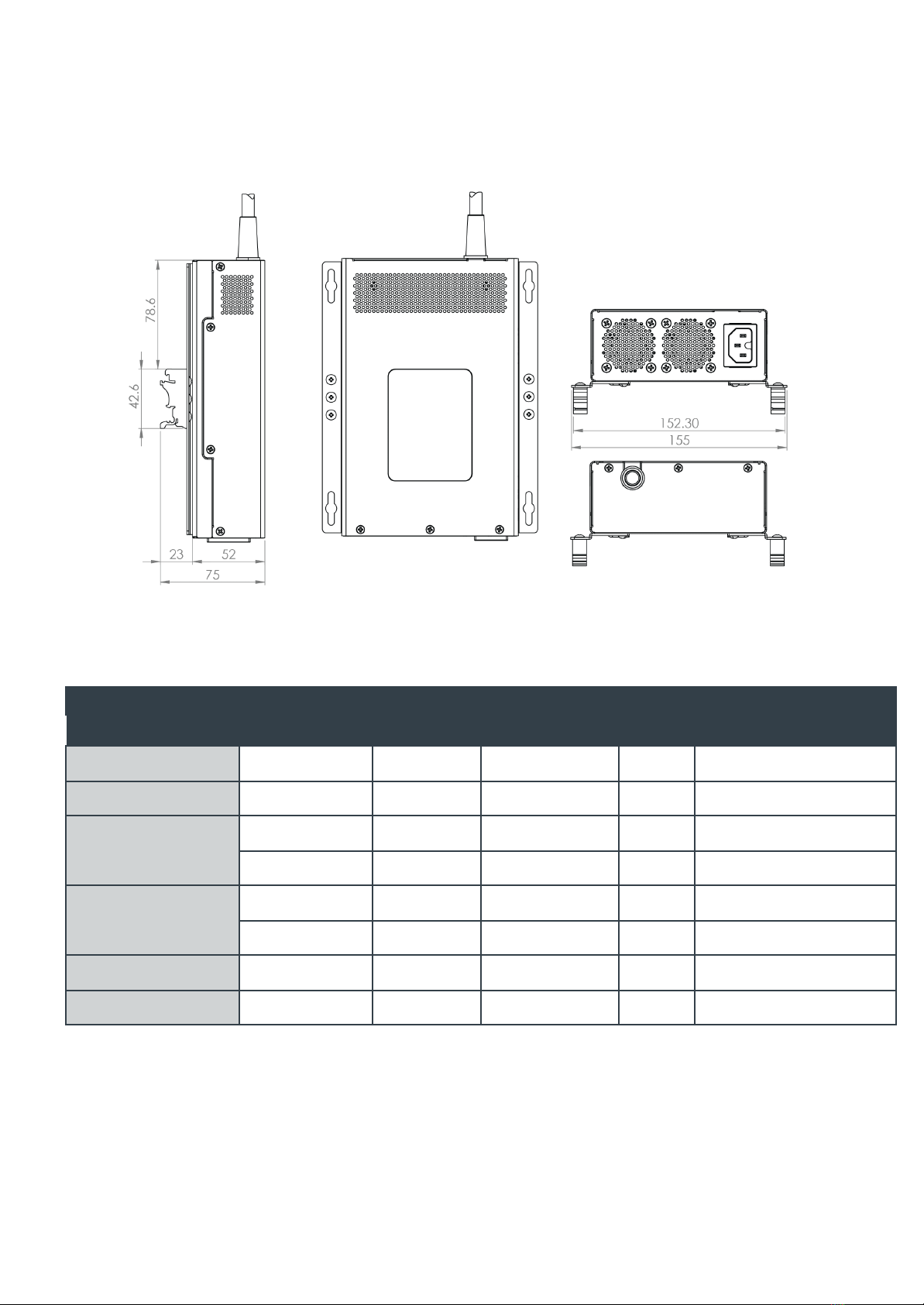
The PS1000-1 provides adaptability to users through its unique mounting options and electrical
connections. The power supply can rest on a flat surface using rubber feet, wall mount with included
brackets, and even DIN mount inside electrical enclosures. There are several options for DC output
connections to different types of pin-out configurations. These connections can be achieved through
the use of appropriately wired adapter cables.
The power supply meets international EMC and safety requirements for IT equipment. In addition, the
PS1000-1 has been tested for Railway Immunity EN 50121-3-2, Medical Immunity 60601-1-2, and
Maritime IEC 60945. It has passed shock and vibration requirements specific to EN 50155 and
MIL-STD-810G up to 50G shock and 15 hours of random vibration 5 - 500 Hz at ~10 Grams.
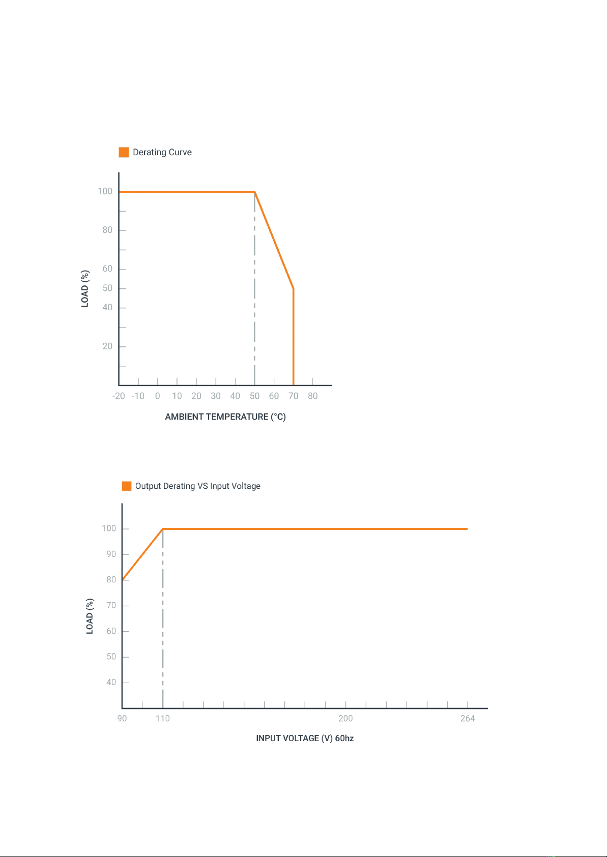
Operating temperatures ranges proved 100% rated power up to 50C and derates linearly to 50% power
at 70C. Forced air cooling with ball bearing fans assures all components remain cool even in
conditions where shock and vibration may be present.
1.2- In-box Accessories
●Wall Mounting Bracket
●C13 Cable (country specific)
●DIN rail clips
3

●Molex to terminal block adapter
1.3 - Product Specifications
Model
PS1000-1
System Dimensions
7.87" x 5" x 2"
200 x 127 x 52 mm
System Weight
7.7 lbs
3.5 kgs
Operating Environmental
Specifications
Operating Temperature: -20-70C *see derating
Operating Humidity: 10% - 90% (non-condensing)
Operating Altitude: 0 - 10,000 feet
Storage Environmental
Specifications
Storage Temperature: -40-80C
Storage Humidity: 5% - 95% (non-condensing)
Storage Altitude: 0 - 50,000 feet
Extra Chassis Features
Wall Mount
DIN Rail Mount
Output Power indicator LED
Regulatory Certifications
FCC 47 CFR Part 15 Subpart B (Class A)
ICES-003
EN 60950-1 & EN 63268-1 Safety
CISPR 32 / EN 55032 IT emissions & immunity
CISPR 11 Industrial / Medical emissions & immunity
EN 50121-3-2 Railway Immunity
WEEE Directive (2012/19/EU)
RoHS 3 (2015/863/EU)
IEC 60601-1-2, 4th ed. - EMC emissions & immunity
EN 60945 Maritime EMC - for bridge and deck zones
EN 50121-3-2 Railway Immunity
4

IEC/UL/EN 62368-1 + CB Scheme
IEC 60068-2-64 Vibration Test (10grms 5-500Hz)
IEC 600068-2-27 Shock (30G 18ms / 50G 11ms)
MIL-STD-810G Method 514.6 Vibration Test
MIL-STD-810G Method 516.6 Shock Test (40G saw)
Countries
USA, Canada, Mexico, Europe, UK, Australia, New
Zealand, China, Taiwan, India, Japan
1.4 - Exterior Features and Dimensions
5

1.4.1 Wall Mounting Exterior Features and Dimension
6

1.4.2 DIN Mounting Exterior Features and Dimension
1.5 Input Electrical Specifications
Characteristic
Minimum
Typical
Maximum
Units
Notes
Voltage
90
100-240
264
Vrms
Frequency
47
50-60
63
Hz
Current
12
Arms
@115 VAC
6
Arms
@230 VAC
Inrush current
40
A
115Vac @25°C
80
A
230Vac @25°C
Leakage current
3.5
mA
Measured at 230 VAC
Power factor
>0.95
230Vac @ 1000 W output
7

1.6 Output Electrical Specifications
Characteristic
Minimum
Typical
Maximum
Units
Notes
Voltage
48
V
Load
0
20.83
A
Power
0
1000
W
Derated to 500 W @ 70°C
Peak Load
26
A
Up to 15ms duration
Regulation
1%
Line Regulation
1%
Ripple and Noise
480
mV
With 0.1uF and 10uF across
output. 20MHz BWL
Hold up time
16
ms
Output within 5% @ 800 W
Power on time
2000
ms
No load
Overshoot
5%
Max overshoot during turn-on /
turn-off
Transient response
5%
Recovers to 1% within 1ms for
25%-75% load step
8

1.7 Output Indicator light
The PS1000-1 has a LED indicator which indicates the status of the 48V DC output. The LED should
be strongly lit. A dim or flickering LED indicates a potential problem on the output.
9

1.8 Thermal Derating
1.9 Input Voltage Derating
10

2 - Connectors
The attached DC output cable is terminated with an eight pin Molex connector (Molex 39-01-2085).
The pinout is provided below. Mate with Molex 39-01-3089 or connector from a similar series.
Pin
1-4
DC -
5-8
DC +
4-Pin DIN power pinout
The adapter pictured below is included with the power supply. This adapter may be used to wire the
power supply to a 5mm pitch terminal block. The pinout of the adapter is provided below.
11

3 - Mounting Instructions
3.1 - Wall Mount & DIN Rail Mounting
The PS1000-1 has optional Wall Mount brackets (included) and DIN Rail mounting brackets (SKU :
MTD102) available for purchase
For Wall Mounting, follow steps below :
Step 1: Remove rubber mounting feet. Retain the screws and discard rubber washers.
Step 2: Align the four screw holes on the bottom of the system with the respective holes on the
mounting brackets.
Step 3: Attach wall mounting brackets to the system using the retained M3 screws (M3X0.5 Phillips
Screw, 4mm Long). Caution! Using screws longer than 4mm may damage the power supply.
Step 4 : Install system to surface using keyhole slots on wall mount brackets and appropriate
hardware for the surface (not provided).
For DIN Rail Mounting, follow the below steps:
Step 1: Follow steps 1-4 from the Wall Mounting section.
Step 2: Align the mounting holes of the din clip bracket to the three mounting holes on the wall mount
bracket.
Step 3: Install the din clips to the wall mount brackets using supplied screws and a Phillips head
screwdriver.
Step 6: Mount system onto the DIN rail.
12

Note: The mounting brackets are required to support 3x the hanging weight of the system. The
mating surface and hardware must be capable of supporting the same load.
13

4 - Protection features
4.1 Over Voltage Protection
+48V output: Over voltage protection>115% (no lower than 115% and no higher than 140%)
Protection type: latch-mode over voltage protection
4.2 Over Current Protection
Overcurrent protection >130% of nominal current (no lower than 130% and no higher than 160%)
Protection type: recovers automatically after fault condition is removed
4.3 Over Temperature Protection
Environment temperature 55℃~70℃at full load.
Protection type: recovers automatically after fault condition is removed
4.4 Short Protection
Output to GND.
Protection type: recovers automatically after fault condition is removed
14

5. Appendices
5.1 Appendix A: Regulatory Compliance
5.1.1 CE Statement
The power supply complies with the relevant IT equipment directives for the CE mark. Modification of
the power supply may void the certifications. The product was tested as a Class A device intended for
industrial / commercial settings.
5.1.2 FCC Statement
This device complies with part 15 of the FCC rules as a Class A device. Operation is subject to the
following two conditions: (1) this device may not cause harmful interference and (2) this device must
accept any interference received, including interference that may cause undesired operation.
This equipment has been tested and found to comply with the limits for a Class A digital device,
pursuant to part 15 of the FCC Rules. These limits are designed to provide reasonable protection
against harmful interference when the equipment is operated in a commercial environment. This
equipment generates, uses, and can radiate radio frequency energy and, if not installed and used in
accordance with the instruction manual, may cause harmful interference to radio communications.
Operation of this equipment in a residential area is likely to cause harmful interference in which case
the user will be required to correct the interference at his own expense.
Warning: Operation of this equipment in a residential environment could cause radio interference.
5.1.3 ISED
This device complies with Industry Canada license-exempt RSS standard(s). Operation is subject to
the following two conditions: (1) this device may not cause interference, and (2) this device must
accept any interference, including interference that may cause undesired operation of the device.
Le présent appareil est conforme aux CNR d'Industrie Canada applicables aux appareils radio
exempts de licence. L'exploitation est autorisée aux deux conditions suivantes: (1) l'appareil ne doit
pas produire de brouillage, et (2) l'utilisateur de l'appareil doit accepter tout brouillage radioélectrique
subi, même si le brouillage est susceptible d'en compromettre le fonctionnement.
CAN ICES-003(A) / NMB-003(A)
15

5.1.4 UKCA
The computer system was evaluated for EMC standards as a class A device. The computer complies
with the relevant IT equipment directives for the UKCA mark.
5.1.5 VCCI
This is a Class A product based on the standard of the Voluntary Control Council for Interference
(VCCI). If this equipment is used in a domestic environment, radio interference may occur, in which
case the user may be required to take corrective actions.
5.1.6 BSMI
Warning: To avoid electromagnetic interference, this product should not be installed or used in a
residential environment.
警告:為避免電磁干擾,本產品不應安裝或使用於住宅環境。
5.1.7 CCC
l本产品适用于信息技术及音视频设备使用。
l本产品适用于热带气候条件使用。
l本产品允许最大工作环境温度是70℃。
l本产品适用于海拔5000m及以下地区使用。
l警告:在居住环境中,运行此设备可能会造成无线电干扰。
16

l本產品適用於熱帶氣候條件使用。
l本產品允許最大工作環境溫度是70℃。
l警告:為避免電磁干擾,本產品不應安裝或使用於住宅環境。
17
設備名稱: 電源供應器 ,型號(型式):PS1000-1
單元Unit
限用物質及其化學符號
鉛Lead
(Pb)
汞Mercury
(Hg)
鎘Cadmium
(Cd)
六價鉻
Hexavalent
chromium
(Cr+6)
多溴聯苯
Polybromin
ated
biphenyls
(PBB)
多溴二苯醚
Polybrominat
ed diphenyl
ethers (PBDE)
外殼/ case
-
○
○
○
○
○
線材/ wire
-
○
○
○
○
○
主電路板/ The main circuit
board
○
○
○
○
○
○
副電路板 (PFC 卡)/ Vice board
○
○
○
○
○
○
電阻/Resistor
○
○
○
○
○
○
電容/ Capacitance
○
○
○
○
○
○
二極體/Diode
-
○
○
○
○
○
貼片二極體/SMD DIODE
-
○
○
○
○
○
集成電路/IC
-
○
○
○
○
○
變壓器/線圈/ Transformer/coil
○
○
○
○
○
○
保險絲/FUSE
○
○
○
○
○
○
散熱片/ Heat sinks
○
○
○
○
○
○
麥拉絕緣片/ Mylar insulation
slices
○
○
○
○
○
○
AC開關和插座/Switch and
socket
○
○
○
○
○
○
風扇/Fan
○
○
○
○
○
○
塑膠零件/ Plastic parts
○
○
○
○
○
○
包裝材料/ Packaging materials
○
○
○
○
○
○
備考1.〝超出0.1 wt %〞及〝超出0.01 wt %〞係指限用物質之百分比含量超出百分比含量基準值。
備考2.〝○〞係指該項限用物質之百分比含量未超出百分比含量基準值。
備考3.〝-〞係指該項限用物質為排除項目。

Symbols used:
Indoor use only
The appliance shall not be disposed together with the
normal waste. It must be recycled.
5.2 Appendix B: Safety Precautions, Safeguards & Information
Do not open and modify the device! The device complies with various national and international
Safety, EMC and Environmental requirements per various standards.
Modification of the device may void certifications, warranty and/or cause possible injury to the user.
5.2.1 Safe use and installation instructions
1. Read the entire manual before using the product.
2. Install the device securely per users manual instructions.
3. Care must be taken handling the device to prevent injury to self or possibility of damaging the
unit.
4. The appliance is suitable for use together with ITE equipment only.
5. The appliance is suitable for moderate climates only.
6. The maximum ambient temperature during use of the appliance must not exceed 70°C.
7. Naked flame sources, such as candles, must not be placed on the appliance.
8. The appliance and the mains-socket must all times be easily accessible.
9. In case of broken cords or plugs the appliance must be disposed of.
10. The appliance does not require regular maintenance. If you want to clean it, please use only a
dry cloth or brush. Do not clean the device with liquids. To prevent injury to self and/or
damage to the device the unit must be powered down and all connecting power and other
peripherals shall be disconnected prior to cleaning.
11. This product is suitable for altitudes less than 5000m.
12. Wall or ceiling mounting device requires use of a mounting plate or bracket. The plate or
bracket must be of metal construction and have a minimum thickness of 1mm.
13. Use M3x0.5mm screws to attach mounting plate or mounting brackets to threaded holes on
bottom or rear of chassis. Screws should be a minimum length of 4mm. Add 1mm of screw
length for every mm of additional thickness of plate or bracket beyond 1.5mm.
14. Ambient operating temperature must be between -20 °C to 70 °C with a non-condensing
relative humidity of 10-90%.
15. The device can be stored at temperatures between -40 °C to 80 °C.
16. Keep the device away from liquids and flammable materials. Not to be installed in a
hazardous environment.
17. Allow adequate space around all sides of the device for proper cooling and to not exceed its
maximum operating temperature limit. Keep air vents unobstructed.
18

18. This device is intended for indoor operation only.
5.2.2 Précautions et guide d’installation
1. Lisez l'intégralité du manuel avant d'utiliser le produit.
2. Installez l'appareil en toute sécurité selon les instructions du manuel de l'utilisateur.
3. Des précautions doivent être prises lors de la manipulation de l'appareil pour éviter de se
blesser ou d'endommager l'appareil.
4. L'appareil ne peut être utilisé qu'avec un équipement ITE.
5. L'appareil convient uniquement aux climats tempérés.
6. La température ambiante maximale pendant l'utilisation de l'appareil ne doit pas dépasser
70°C.
7. Les sources de flammes nues, telles que les bougies, ne doivent pas être placées sur
l'appareil.
8. L'appareil et la prise de courant doivent toujours être facilement accessibles.
9. En cas de cordons ou de prises cassés, l'appareil doit être jeté.
10. L'appareil ne nécessite pas d'entretien régulier. Si vous souhaitez le nettoyer, veuillez utiliser
uniquement un chiffon sec ou une brosse. Ne nettoyez pas l'appareil avec des liquides. Pour
éviter de se blesser et/ou d'endommager l'appareil, l'appareil doit être éteint et toutes les
alimentations et autres périphériques doivent être déconnectés avant le nettoyage.
11. Ce produit convient aux altitudes inférieures à 5000 m.
12. Le dispositif de montage mural ou au plafond nécessite l'utilisation d'une plaque ou d'un
support de montage. La plaque ou le support doit être en métal et avoir une épaisseur
minimale de 1 mm.
13. Utilisez des vis à tête bombêe M3x0,5 mm pour fixer la plaque de montage ou les supports
de montage aux trous filetés au bas ou à l'arrière du châssis. Les vis doivent avoir une
longueur minimale de 4 mm. Ajoutez 1 mm de longueur de vis pour chaque mm d'épaisseur
supplémentaire de plaque ou de support au-delà de 1,5 mm.
14. La température ambiante de fonctionnement doit être comprise entre -20 °C et 70 °C avec
une humidité relative sans condensation de 10 à 90 %.
15. L'appareil peut être stocké à des températures comprises entre -40 °C et 80 °C.
16. Gardez l'appareil à l'écart des liquides et des matériaux inflammables. Ne pas installer dans
un environnement dangereux.
17. Prévoyez un espace suffisant autour de tous les côtés de l'appareil pour un refroidissement
correct et pour ne pas dépasser sa limite de température de fonctionnement maximale.
Maintenez les bouches d'aération dégagées.
18. Cet appareil est destiné à une utilisation en intérieur uniquement.
19
This manual suits for next models
3
Table of contents
Popular Power Supply manuals by other brands

Elektro-Automatik
Elektro-Automatik EL 9000 B 15U Series operating guide

Ulvac
Ulvac DC-10 Operation manual

Monacor
Monacor PSS-600E quick start guide

SamplexPower
SamplexPower SEC-1212CE owner's manual

Elektro-Automatik
Elektro-Automatik PSI 9000 DT Series operating manual

YASKAWA
YASKAWA PS-A10LB installation manual

Stanley
Stanley GT13 Safety, operation and maintenance user's manual

Gradus Group
Gradus Group SENAL PHANTOM PS-48B quick start guide

Aktakom
Aktakom APS-3310 user manual

TOOQ
TOOQ TQEP-750SP user manual

Riello UPS
Riello UPS CSS sentryum CBM installation manual

Honeywell
Honeywell PS1202A00 installation instructions