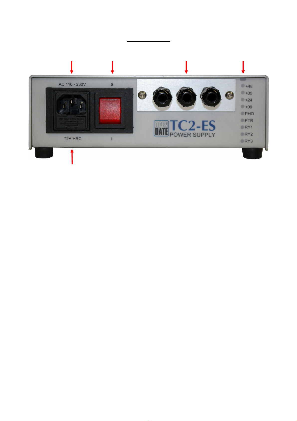
I/O connection details
TO AVOID DAMAGE AND RISK OF ELECTRIC SHOCK CONNECTIONS MUST ONLY
BE MADE WITH THE POWER CABLE DISCONNECTED.
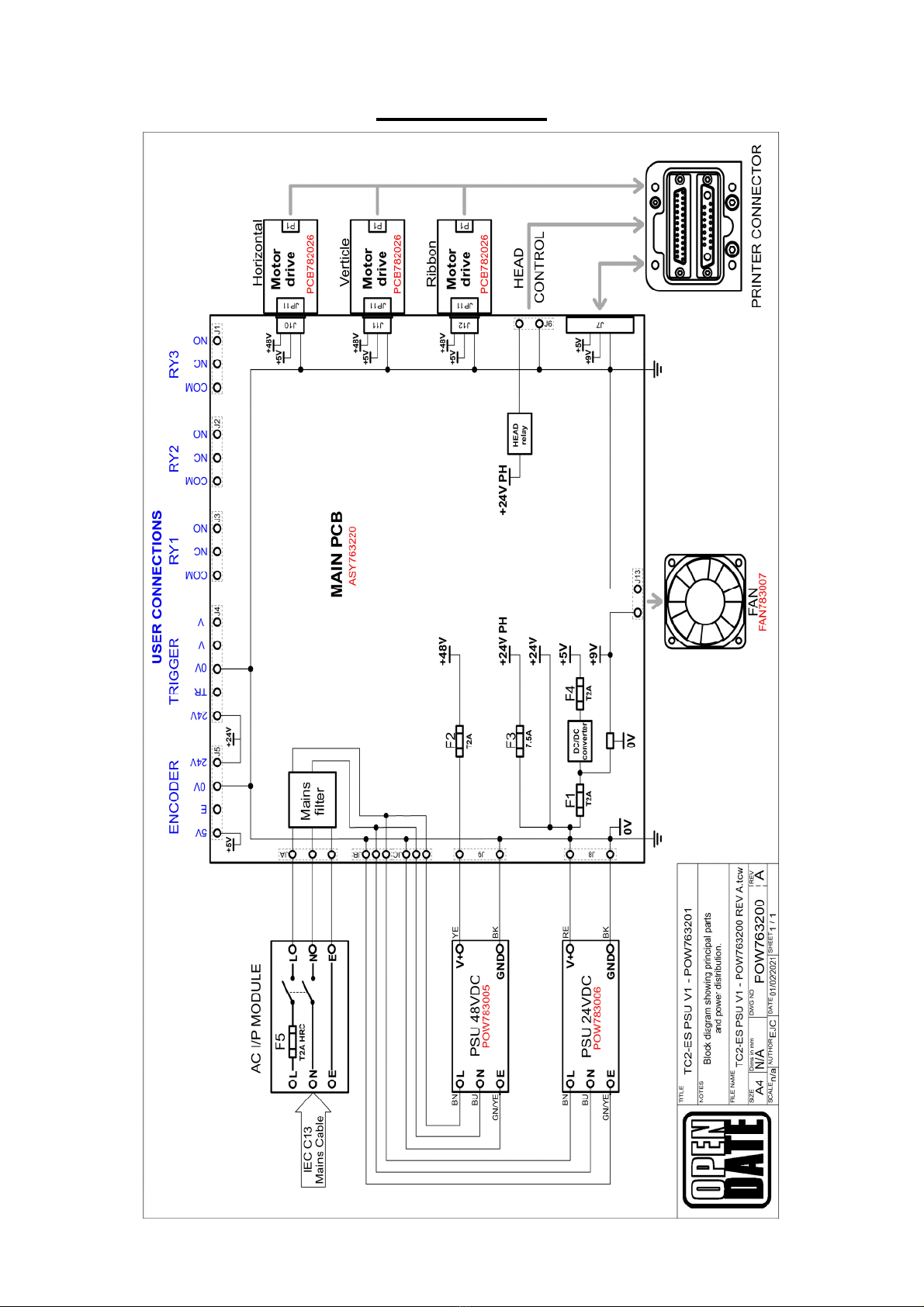
(Refer to the diagram on page 5.)
The protective earth (mains conductor), the 0V terminals of the internal power supply modules,
the 0V of the print head and the 0V from the printer electronics are all common.
ENCODER (J5)
Used with continuous printers only.
Connect encoder +ive wire to 5V or 24V (depending on encoder voltage)
Connect encoder 0V wire to 0V terminal
Connect encoder pulse output (Q) to E terminal
Maximum current from 5V terminal; 100mA
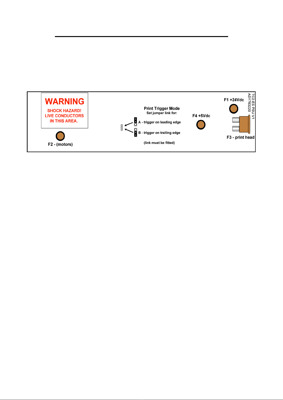
PRINT TRIGGERING:
See page 7 for selection of Leading or Trailing print trigger.
Volt free triggering
Use external relay or switch with volt free contacts.
Connect the Trig (TR) terminal to 24V terminal or.
Connect the Trig (TR) terminal to 0V terminal.
~~~~~~~~~~~~~~Do not connect the 24V and 0V terminals together.~~~~~~~~~~~~~~~
Voltage triggering
Connect voltage trigger source to terminals V and V. Any voltage from 10 to 30V may be used,
polarity is un-important.
PNP/NPN sensor triggering
Connect sensor +ive wire (usually brown) to 24V terminal
Connect sensor 0V wire (usually blue) to 0V terminal
Connect sensor output wire (Q, usually black or white) to TR terminal (See * below)
*Diode type 1N4007 may needed in the Q wire from the sensor for correct
operation. (anode to Q, cathode to TR )
The PSU configures automatically for PNP or NPN sensors.
RELAY 1,2,3
SPCO relays with voltage free contacts.
(Maximum contact ratings; 0.6A @ 125Vac, 0.6A @ 110Vdc, 2A @ 30Vdc)
Relay is energised when blue LED on front panel is lit
COM is connected to NC when the relay is not energised.
COM is connected to NO when the relay is energised.
*If Issues with Voltage triggering are noted an additional Voltage Isolation relay may be installed.
Page 6 ©2021 Open Date Equipment Ltd. All rights reserved. June 2021