Opendesk.ch STEELFORCE PRO 570 SLS User manual

English
Deutsch
Nederlands
Assembly Manual
Read this manual thoroughly and store in a safe place.
Montageanleitung
Bitte sorgfältig lesen und sicher aufbewahren.
Montagehandleiding
Lees deze handleiding aandachtig door en bewaar deze goed.
STEELFORCE PRO 570 SLS
WELDING TABLE
SLS-WDT-EN-DE-NL

2
English
Content
1GENERAL .........................................................................................................................................................................5
1.1 Local value of the assembly/operating manual ..............................................................................................5
1.2 Intended use ........................................................................................................................................................5
1.3 Improper use ........................................................................................................................................................ 5
1.4 Danger .................................................................................................................................................................. 5
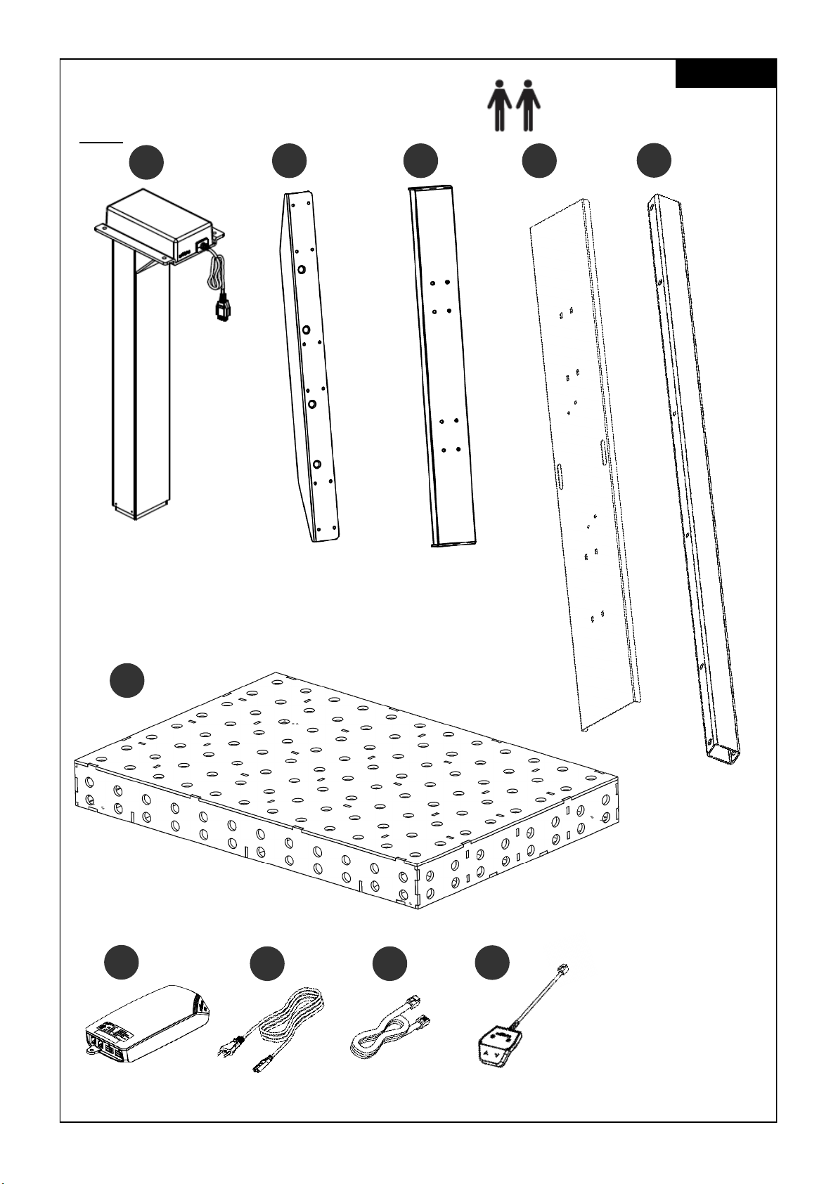
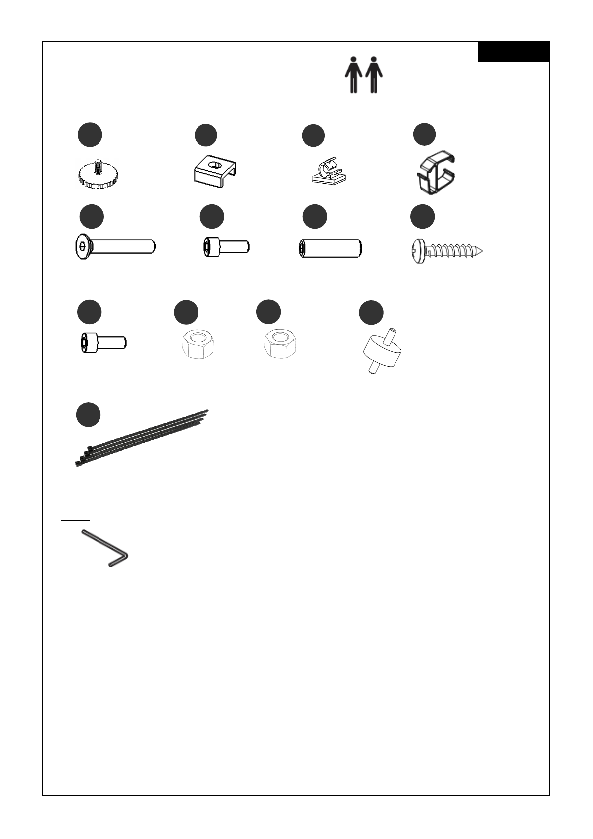
1.5 Content box ......................................................................................................................................................6-7
2SAFETY INFORMATION ....................................................................................................................................................8
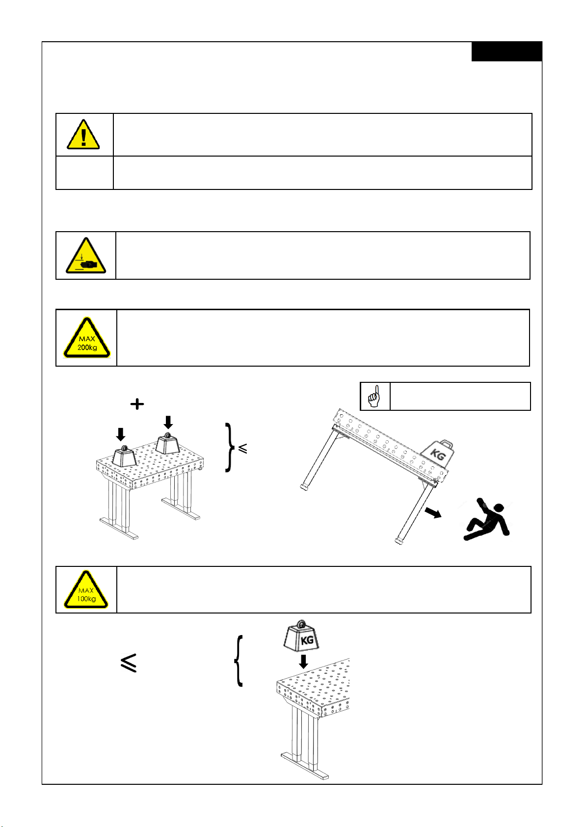
2.1 Symbols/warnings ................................................................................................................................................ 8
2.2 Symbols used on the workstation frame ............................................................................................................8
2.3 Maximum weight allowed on frame .................................................................................................................. 8
2.4 Maximum weight allowed per column ................................................................................................................... 8
2.5 Organizational measures ....................................................................................................................................9
2.6 Informal safety measures ....................................................................................................................................9
2.7 Note for those assembling the workstation .......................................................................................................9
2.8 Transport and assembly ......................................................................................................................................9
2.9 Use of the workstation frame ..............................................................................................................................9
2.10 Specific dangers ..................................................................................................................................................9
2.11 In an emergency ..................................................................................................................................................9
2.12 Maintenance and upkeep .................................................................................................................................9
2.13 Cleaning..............................................................................................................................................................10
2.14 Persistent risks ...................................................................................................................................................... 10
3ASSEMBLY ......................................................................................................................................................................11
3.1 Mounting the Feet ..............................................................................................................................................11
3.2 Mounting the Crossbar and Top Support .........................................................................................................12
3.3 Mounting the Power Supply underneath the Crossbar Cover .......................................................................13
3.4 Mounting the Cossbar Cover.............................................................................................................................13
3.5 Mounting the Rubber Buffer and Welding Top ................................................................................................14
3.6 Mounting the Hand Switch underneath the Welding Top ..............................................................................15
3.7 Connecting the Electrical Components ..........................................................................................................16
3.8 Clearance around the wall or moving parts 25mm of the Welding Top.......................................................16
3.9 Frame Test............................................................................................................................................................ 17
4 TECHNICAL SPECIFICATIONS ..................................................................................................................................18-19
5 OPERATION AND INDICATORS ..................................................................................................................................... 20
5.1Indicators ......................................................................................................................................................................20
6 TROUBLESHOOTING ......................................................................................................................................................20
7 CUSTOMER SERVICE ..................................................................................................................................................... 21
8 MANUFACTURER ...........................................................................................................................................................21
9 RECYCLING ...................................................................................................................................................................21
9.1 Taking the workstation out of active duty ....................................................................................................... 21
9.2 Taking the workstation apart ............................................................................................................................ 21
9.3 Recycling............................................................................................................................................................. 21

3
Inhaltsverzeichnis
1ALLGEMEINES................................................................................................................................................................. 22
1.1 Bedeutung der Betriebs–und Montageanleitung ......................................................................................... 22
1.2 Sachgemäße Verwendung............................................................................................................................... 22
1.3 Sachwidrige Verwendung................................................................................................................................. 22
1.4 Gefahr ................................................................................................................................................................. 22
1.5 Lieferumfang.................................................................................................................................................. 23-24
2SICHERHEITSHINWEISE ................................................................................................................................................... 25
2.1 Symbol–und Hinweiserklärungen ..................................................................................................................... 25
2.2 Verwendete Symbole am Tischgestell ............................................................................................................. 25
2.3 Zulässiges Gesamtgewicht auf dem Tischgestell............................................................................................. 25
2.4 Zulässiges Gesamtgewicht pro Säule ............................................................................................................... 25
2.5 Organisatorische Maßnahmen ......................................................................................................................... 26
2.6 Empfohlene Sicherheitsmaßnahmen ............................................................................................................... 26
2.7 Hinweise zur Montage........................................................................................................................................ 26
2.8 Transport und Montage ..................................................................................................................................... 26
2.9 Benutzung des Tischgestells............................................................................................................................... 26
2.10 Besondere Gefahrenstellen............................................................................................................................... 26
2.11 Hinweise für den Notfall ..................................................................................................................................... 26
2.12 Wartung und Instandhaltung ............................................................................................................................ 26
2.13 Reinigung ............................................................................................................................................................ 27
2.14 Restrisiken ............................................................................................................................................................ 27
3MONTAGE...................................................................................................................................................................... 28
3.1 Montage der Kufen............................................................................................................................................ 28
3.2 Montage der Traverse und Plattenträger......................................................................................................... 29
3.3 Montage des Netzteils unterhalb der Traversenabdeckung.......................................................................... 30
3.4 Montage der Traversenabdeckung ................................................................................................................. 30
3.5 Montage der Gummipuffer und Schweißplatte.............................................................................................. 31
3.6 Montage des Handschalters unterhalb der Schweißplatte ........................................................................... 32
3.7 Verbinden der elektrischen Komponenten...................................................................................................... 33
3.8 Sicherheitsabstand zur Wand oder beweglichen Teilen von 25 mm um die Tischplatte ............................ 33
3.9 Test und Inbetriebnahme................................................................................................................................... 34
4 TECHNISCHE SPEZIFIKATIONEN................................................................................................................................35-36
5 BETRIEBSHINWEISE.......................................................................................................................................................... 37
5.1Fehlfunktionen .............................................................................................................................................................. 37
6 FEHLERBEHEBUNG.......................................................................................................................................................... 37
7 KUNDENDIENST .............................................................................................................................................................. 38
8 HERSTELLER..................................................................................................................................................................... 38
9 ENTSORGUNG................................................................................................................................................................ 38
9.1 Außerbetriebnahme des Tischgestells .............................................................................................................. 38
9.2 Tischgestell abbauen und ggf. zerlegen.......................................................................................................... 38
9.3 Entsorgung .......................................................................................................................................................... 38
Deutsch

4
Nederlands
Inhoudsopgave
1ALGEMEEN ...................................................................................................................................................................39
1.1 Het belang van de montage–en bedieningshandleiding ............................................................................39
1.2 Beoogd gebruik ..................................................................................................................................................39
1.3 Onjuist gebruik.....................................................................................................................................................39
1.4 Gevaar.................................................................................................................................................................39
1.5 Inhoud verpakking ........................................................................................................................................40-41
2VEILIGHEIDSINSTRUCTIES ...............................................................................................................................................42
2.1 Verklaring van symbolen en instructies.............................................................................................................42
2.2 Gebruikte symbolen op het frame....................................................................................................................42
2.3 Maximaal toegestaan gewicht op het frame ................................................................................................42
2.4 Maximaal toegestaan gewicht per kolom .......................................................................................................... 42
2.5 Organisatorische maatregeln ...........................................................................................................................43
2.6 Informele veiligheidsmaatregelen ...................................................................................................................43
2.7 Vereisten aan de monteurs ...............................................................................................................................43
2.8 Transport en montage........................................................................................................................................43
2.9 Gebruik van het frame.......................................................................................................................................43
2.10 Specifieke gevaren.............................................................................................................................................43
2.11 Instructies voor noodgevallen ...........................................................................................................................43
2.12 Onderhoud en instandhouding ........................................................................................................................43
2.13 Reiniging ..............................................................................................................................................................44
2.14 Overige risico’s....................................................................................................................................................44
3MONTAGE .....................................................................................................................................................................45
3.1 Montage van de voeten ...................................................................................................................................45
3.2 Montage van de crossbar en bladdragers......................................................................................................46
3.3 Montage van de elektrische componente onder de crossbar cover...........................................................47
3.4 Montage van de crossbar .................................................................................................................................48
3.5 Montage van de rubberen buffers en lasplaat ...............................................................................................48
3.6 Montage van de handbediening onder de lasplaat .....................................................................................49
3.7 Ansluiten van de elektrische componenten ...................................................................................................50
3.8 Afstand van 25 mm tussen de muur of andere objecten en het werkblad..................................................50
3.9 Frame test............................................................................................................................................................51
4 TECHNISCHE SPECIFICATIES .................................................................................................................................... 52-53
5 BEDIENING EN GEBRUIKSAANWIJZINGEN ...................................................................................................................54
5.1 Gebruiksaanwijzingen ........................................................................................................................................54
6 PROBLEEMOPLOSSINGEN .............................................................................................................................................54
7 KLANTENSERVICE ..........................................................................................................................................................55
8 FABRIKANT ....................................................................................................................................................................55
9 RECYCLING ...................................................................................................................................................................55
9.1 Buitenbedrijfstelling van het frame....................................................................................................................55
9.2 Demontage van het frame ...............................................................................................................................55
9.3 Recycling.............................................................................................................................................................55

5
English
1 General
1.1 Local value of the assembly/Operating Manual
The guiding principle for safe use and trouble-free operation of this workstation frame is knowledge of
basic safety information and regulations. This assembly/operating manual contains the most important
information needed for assembling and operating the workstation frame safely. This assembly/
operating manual, in particular the safety information contained herein, must be observed by any
person building the frame and working on the finished surface. More importantly, the rules and regula-
tions applying to accident prevention in the locality in which the workstation frame is to be used must
be observed at all times.
1.2 Intended use
The workstation frame must be used only as a height-adjustable workstation for sitting/standing use in
offices or other enclosed areas. The frame must be used for this purpose only. Any other use than the
above shall be deemed improper. The manufacturer can in no way be held liable for damage arising
from improper use. This appliance can be used by children aged from 8 years and above and persons
with reduced physical, sensory or mental capabilities or lack of experience and knowledge if they
have been given supervision or instruction concerning use of the appliance in a safe way and under-
stand the hazards involved. Children should be supervised to ensure that they do not play with the
appliance, cleaning and user maintenance shall not be made by children without supervision.
Intended use shall also include:
• Observation of all information from the assembly/operating manual and
• Prohibition of any sort of addition to/conversion of the workstation.
1.3 Improper use
• Never use the workstation frame to lift people or loads.
• Do not exceed the maximum load of the workstation frame.
• Operate workstation only with power supply unit which is included in delivery.
1.4 Danger
Improper connection of the workstation frame grounding conductor can result in a risk of electric
shock. Check with a qualified electrician if you are in doubt as to whether the product is properly
grounded. Do not modify the plug provided with the product.
If the supply cord is damaged, it must be replaced by a special cord or assembly available from the
manufacturer or its service agent.
WARNING: Any changes or modifications not expressly approved by the manufacturer could
void the user’s authority to operate the equipment.

6
1.5 Content Box Assembly requires 2 people!
English
Items
2x
2 2x
4
2x
7 2x
8
4x
1
1x
9 1x
10
2x
3 4x
5
1x
6

7
1.5 Content Box Assembly requires 2 people!
English
Hardware Kit
Tools
M8x50
16x
E 16x
F
M6x16
16x
G
M10x35 4.5x20
H
4x
A 8x
B 2x
C 12x
D
40x
38x
6x
i
M5x12
8x
K 8x
L
Please do not use item B/C/D/G/H for this model.
4x
J
M5 M8
4x
M
You can use the cable ties
to organize he cables.

8
100 kg/ side
2 Safety Information
2.1 Symbols/Warnings
The assembly/operating manual uses the following terms and signs to indicate dangers:
This symbol indicates an immediate threatening situation for any person’s life or health.
Failure to adhere to such information may have serious consequences for health, or
could even result in life-threatening injury or death.
This symbol indicates important information. Failure to adhere to such information
could lead to damage to the workstation.
2.2 Symbols used on the workstation frame
Do not place objects or parts of the body under the workstation frame or between
the cross members. This could cause serious injury or even result in death.
200 kg
> 200 kg
200KG
2.4 Maximum weight allowed per column
Do not exceed the maximum permitted load of 100 kg (including table top) on a
column. Overloading a frame may cause breakage and close by individuals
may suffer serious injuries as a consequence.
English
2.3 Maximum weight allowed on frame
Do not exceed the maximum permitted load of 200 kg including table top
on the workstation frame. Avoid unbalanced load, distribute the weight evenly, oth-
erwise overload may occur. Overloading a frame may cause breakage and close by
individuals may suffer serious injuries as a consequence.
The entire weight should be
evenly distributed.
Example :

9
2.5 Organizational measures
• The workstation frame can best be assembled by two people. Turning the frame, once the work
surface has been fitted, is a task in particular which requires two people!
2.6 Informal safety measures
• Keep the assembly/operating manual in the place where the workstation frame is used at all
times.
• Make sure that all safety information on the table (see Section 2.2, Symbols used on the work-
station frame) is legible, replacing the same if necessary.
2.7 Note for those assembling the workstation
• The workstation must be assembled/worked on by persons over the age of 16.
• The persons referred to above must have read and understood the assembly /operating manu-
al.
2.8 Transport and assembly
• The workstation frame must be moved by two persons only, and in such cases must be retract-
ed.
• Do not drag or pull the workstation frame over the floor.
• Assemble the workstation frame with the supplied tools only. They are the only tools which en-
sure that the screws can be tightened to the correct torque.
2.9 Use of the workstation frame
• Do not allow children to use the workstation frame unsupervised. Children may be unaware of
the dangers presented by the workstation frame. They would be in serious danger of injuring
themselves, possibly even with fatal consequences. Further adjustment must then be impossible
as a safeguard against use by children.
• The workstation frame must only be used in appropriate areas.
• Do not use the workstation frame on an uneven surface. In such conditions it will not be steady.
• Never exceed the maximum load on the workstation frame.
2.10 Specific dangers
• When adjusting the height of the frame there is danger of injury. Make sure that there is no-one
else in the immediate surroundings of the frame.
• When assembling the workstation frame, make sure there is ample space to avoid collisions (i.e.
inclination of roof, fixed objects, filing cabinets, waste-paper bins etc.) in all imaginable direc-
tions.
• Make sure there is ample space to avoid collisions if there are objects on the work surface such
as computers or computer peripherals.
• Make sure there is clearance of at least 25 mm from all other furniture, all around the workstation
frame.
2.11 In an emergency
• Stop using the workstation frame at once if you notice anything unusual (strange sounds etc.).
• Have the workstation frame repaired by specialists. Refrain from using the workstation frame until
it has been successfully repaired.
2.12 Maintenance and upkeep
• The workstation frame and its components are low-maintenance items and need no special
regular maintenance.
• Do not perform any repairs on the work surface or other components yourself.
• Do not alter the construction of the work surface or its frame.
• Any faulty components removed must be replaced with new, original components from the
manufacturer. Use only original replacement parts made by the manufacturer. Have any such
work carried out by a specialist, making reference to this Assembly/operating manual.
English

10
2.13 Cleaning
• Always unplug this workstation from the electrical outlet before cleaning.
• Dust the workstation frame once a week with a dry cloth.
• Clean the workstation frame with a damp cloth and a weak solution of cleaner once a fort-
night.
2.14 Persistent risks
This workstation frame has been built to the state of the art and to recognized safety regulations.
Nonetheless, its use may constitute a risk to the health and safety of users or third parties, damage to
the workstation frame or to other items. The workstation frame must be used only:
• for the purpose for which it was intended.
• if it is completely safe to do so.
English

11
3 Assembly
Before attempting assembly, read the Safety Information in Section 2.
To protect components and the floor from scratches, it is advisable to use a pad before
assembly. You can, for example, use the supplied cardboard by unfolding it.
English
3.1 Mounting the Feet
1
A
F
3
4x
1

12
3.2 Mounting the Crossbar and Top Support English
2
E
2
5

13
English
3.3 Mounting the Power Supply underneath the Crossbar Cover
3.4 Mounting the Crossbar Cover
3
4
J
i
Put the crossbar cover with the mounted power supplies onto the crossbars.
Additional screws are not necessary.
4

14
3.5 Mounting the Rubber Buffer and Welding Top English
5
6
L
K

15
3.6 Mounting the Hand Switch underneath the Welding Top English
6
i
10

16
Connect to “COM“
Keep in mind that the desk which you are assembling is height adjustable.
The cables of the electrical components must be able to freely follow the
movement of the desk.
3.7 Connecting the Electrical Components English
Connect to “HS“
10
8Connect to “HS“
8
Controller 1 Controller 2
7
8 8
9
Controller 1
7
Controller 2
9
10
25mm
(1”)
25mm
(1”)
25mm
(1”)
Allow a minimum clearance of 25mm from the edge of a table top to a wall or
moving parts.
3.8 Clearance around the wall or moving parts 25mm of the table top
7
8
4x
M

17
English
3.9 Frame test
Reset Mode
The first time you put in the plug of the power supply into the socket the height adjustment can only
be operated in the reset-mode. As long as the reset-mode is enabled, the system can only move
downward. In order to use the system normally, please follow the next steps:
• Press and hold the down-button, the system slowly moves downward.
• Please move the system to the lowest position. This position will be used as reference-point (zero-
point).
• Keep the button pressed for a moment when the system has reached the lowest position. This
will end the reset-mode.
• The system can be operated normally now. Press and hold the up- or down-button to move the
system to the desired height. The system stops when you release the buttons.
Please make sure that the workstation frame can move freely and correct at all
times.
In case you need to disconnect cables from the electrical components always be
sure to disconnect power first.
In case the height adjustment is not operating normally, stop using the workstation
frame immediately and disconnect the power. Get in contact with customer service
for further advise
UP DOWN

18
4 Technical Specification
Assembly Manual version SLS-WDT-0EN-DE-NL
Year of construction 2022
Production country Malaysia / Germany
System 1-step
Material Steel, Aluminium and Plastic
Stroke (max.) 330mm (13”)
Frame load (max.) 200 kg
Frame weight ± 55 kg
Speed frame load ± 39 mm/s
Input power 100-120Vac, 60Hz, 5A max
220-220Vac, 50Hz, 2A max
Duty cycle 10 % (2 Minute on / 18 Minutes off)
Noise level < 50 dB(A)
Environmental temperature Use 15 - 30°C
Environmental temperature Storing 10 - 50°C
Humidity Use <85%
Humidity Storing <50%
Maximum Storing time -
Indoor use only!!!
English

19
Minimum Frame Height 830mm (32.7“)
Maximum Frame Height 1160mm (45.7“)
Maximum Stroke 330mm (13“)
Welding Top Width 1200mm (47,2“)
Frame Depth 750mm (29.5“)
Minimum Welding Top Depth 800mm (29.5“)
Maximum Frame Load 200 kg
English
(* General Tolerance = ± 10 mm)
4 Technical Specification
100
128
50
980
649,50
50 50

20
5 Operation and Indicators
Observe the provisions of Section 2, Safety Information on page 7, in particular:
Do not leave children unsupervised with the workstation frame. Children may be un-
aware of the dangers presented by the workstation frame. They would be in serious
danger of injuring themselves, possibly even with fatal consequences.
Do not exceed the maximum time lag of the workstation frame. Make sure there is
ample space to avoid collisions if there are objects on the work surface such as
computers or computer peripherals.
5.1 Indicators
Leave the immediate surroundings of the workstation frame at once if it starts to
move spontaneously. Under no circumstances attempt to operate the workstation
frame.
Stop using the workstation frame at once if you notice anything unusual (strange
sounds, smoke, etc.).
Have the workstation frame repaired by specialists. Refrain from using the workstation
frame until it has been successfully repaired.
Stop using the workstation frame at once if its safety features fail to work as they
should.
6 Troubleshooting
Problem Possible cause Solution
Height adjustment does not
work.
Cables or connectors defective. Check cables for damages
and if necessary replace
them. Power in order?
Height adjustment does not
work.
If cables and connectors have
been checked a possible cause
could be a defective up-down
switch.
Replace up-down switch.
Height adjustment does not
work.
Error in power supply. Initialize reboot.
If your problem couldn´t be solved or is not listed here, please contact your customer
service for further advise.
English
Other manuals for STEELFORCE PRO 570 SLS
1
Table of contents
Popular Welding Accessories manuals by other brands

ThermOweld
ThermOweld CX-7 instructions

ROBOD
ROBOD RINO TEXTILE MAX Manual for Use, Storage and Maintenance

Sundstrom
Sundstrom SR 591 Instructions for use

ESAB
ESAB Warrior YardFeed 200 instruction manual

Miller Electric
Miller Electric and DS-74DX16 owner's manual

Miller Electric
Miller Electric OM-220 390F owner's manual

Lincoln Electric
Lincoln Electric COOLERTIG 4 Operator's manual

InterTest
InterTest iShot Weld-i HD 625 instruction manual

Miller Electric
Miller Electric Arc Welding Power Source Specifications

Miller
Miller MTL-20 Torches owner's manual

Abicor Binzel
Abicor Binzel SR/ABITIG 9 operating instructions

Miller
Miller Axcess 675 owner's manual