manuals.online logo
Brands
  1. Home
  2. •
  3. Brands
  4. •
  5. Opengear
  6. •
  7. Server
  8. •
  9. Opengear IM4000 User manual

Opengear IM4000 User manual

_____________________________________________________________________
Opengear IM4000 and CM4000 User Manual Page 1 of 216
USER MANUAL
IM4200 Infrastructure Manager
and
CM4000 Console Server
User Manual
Rev: 2.1
June 23, 2007
_____________________________________________________________________
Opengear IM4000 and CM4000 User Manual Page 2 of 216
INDEX
INTRODUCTION 7
This Manual 7
Manual Organization 7
Types of users 8
Management Console 9
Manual Conventions 0
INSTALLATION
2.
Models
2.1.1
IM4216-2, IM4216-25 or IM4248-2 Kit Components 12
2.1.2
CM4116 or CM4148 Kit Components 12
2.1.3
CM4008 Kit Components 13
2.1.4
CM4001 Kit Components 14
2.2
Power connection 4
2.1.1
IM4216-2, IM4216-25 and IM4248-2 Power 14
2.2.2
CM4116 or CM4148 Power 15
2.2.3
CM4008 Power 15
2.2.4
CM4001 Power 16
2.2.5
CM4116-48V and CM4148-48V Power 16
2.3
Network connection 7
2.4
Serial Port connection 8
SYSTEM CONFIGURATION 9
3.
Management Console connection 9
3.2
Change the default Password 23
3.3
Set the gateway’s network IP address 24
3.4
System Services selection 27
3.5
Communications Software 29
S TConnector 30
PuTTY 31
SSHTerm 32
3.6
Set the IP address of other IM42xx network ports (IM4200 only) 32
SERIAL PORT AND NETWORK HOST 35
4.
Configuring Serial Ports 36
4.1.1
Common Settings 37
4.1.2
Console Server Mode 38
_____________________________________________________________________
Opengear IM4000 and CM4000 User Manual Page 3 of 216
4.1.3
S T Mode 42
4.1.4
Power Strip Mode 42
4.1.5
Terminal Server Mode 43
4.1.6
Serial Bridging Mode 44
4.1.7
Syslog 45
4.2
Add / Edit Users 46
4.3
Authentication 48
4.4
Network Hosts 50
4.5
Trusted Networks 5
4.6
Serial Port Redirection Client 53
FAILOVER AND OoB DIAL-IN 54
5.
OoB Dial-In access 54
5.1.1
Configure ial-In PPP 55
5.1.2
Set up Windows XP/ 2003 client 58
5.1.3
Set up earlier Windows clients 59
5.1.4
Set up Linux clients 59
5.1.5
Using S TConnector client 60
5.2
OoB broadband access (IM4200 only) 60
5.3
Broadband Ethernet Failover (IM4200 only) 6
5.4
Dial-Out Failover (IM4200 only) 62
SECURE TUNNELING 65
6.
Configuring the IM/CM4000 gateway for SDT Tunneling access to network attached hosts 67
6.2
Establish SDT SSH connection between Client PC and IM/CM4000 gateway 68
6.2.1
etermine the gateway IP address 69
6.2.2
ial in configuration 70
6.2.3
Choosing an SSH client 71
6.2.4
Create the SSH tunnel using S TConnector client 71
6.2.5
Create the SSH tunnel using PuTTY client 73
6.3
Setting up SDT for Remote Desktop access 79
6.3.1
Enable Remote esktop on the target Windows computer to be accessed 79
6.3.2
Configure the Remote esktop Connection client 82
6.4
SDT Secure Tunnel for VNC 87
6.4.1
Install and configure the VNC Server on the computer to be accessed 87
6.4.2
Install, configure and connect the VNC Viewer 90
6.5
Using SDTConnector to browser access the gateway Management Console 93
6.6
Using SDTConnector to Telnet or SSH connect to devices that are serially attached to the gateway 95
6.7
Using SDT to IP connect to hosts that are serially attached to the gateway 98
_____________________________________________________________________
Opengear IM4000 and CM4000 User Manual Page 4 of 216
6.7.1
Establish a PPP connection from the computer’s COM port to IM/CM4000 98
6.7.2
Set up S T Serial Ports on IM/CM4000 104
ALERTS AND LOGGING 06
7.
SMTP and SNMP Settings 06
7.2
Remote Log Storage 08
7.3
Serial Port Logging 08
7.4
Network TCP or UDP Port Logging (IM4200 only) 09
7.5
Configure Port Alerts 0
POWER CONTROL 3
8.
Configuring Serial Port Power Strips 3
8.2
Configuring IPMI Power Management 5
8.2
Configuring browser controlled Power Strips 6
8.3
Controlling Power 7
AUTHENTICATION 8
9.
Remote Authentication Configuration 8
9.2
PAM (Pluggable Authentication Modules) 20
9.3
Secure Management Console Access 2
NAGIOS INTEGRATION 23
0.
Nagios overview 24
0.2
Configuring Nagios 24
0.3 Advanced Configuration 28
0.4 Usage scenarios 33
IM/CM4000 SYSTEM MANAGEMENT 37
.
System Administration and Reset 37
.2
Upgrade Firmware 38
.3
Configure Date and Time 40
STATUS REPORTS 42
2.
Port Access and Active Users 42
2.2
Statistics 43
2.3
Support Reports 43
2.4
Syslog 44
MANAGEMENT 46
3.
Device Management 46
3.2
Port Log Management 47
3.3
Serial Port Terminal Management 47
BASIC CONFIGURATION - LINUX COMMANDS 49
4. The Linux Command line 5
_____________________________________________________________________
Opengear IM4000 and CM4000 User Manual Page 5 of 216
4.2 Administration Configuration 52
System Settings 152
Authentication Configuration 153
4.3 Date and Time Configuration 53
4.4 Network Configuration 54
IP Configuration 154
ial-in Configuration 155
Services Configuration 156
4.5 Serial Port Configuration 57
Serial Port Settings 157
Supported Protocol Configuration 158
Users 158
Trusted Networks 159
4.6 Event Logging Configuration 60
Remote Serial Port Log Storage 160
Alert Configuration 160
4.7 SDT Host Configuration 6
S T host TCP Ports 161
ADVANCED CONFIGURATION 63
5. Advanced Portmanager 64
5.2 External Scripts and Alerts 66
5.3 Raw Access to Serial Ports 68
5.4 IP- Filtering 69
5.5 Modifying SNMP Configuration 7
5.6 Secure Shell (SSH) Support 7
Configuring SSH Public Key Authentication (Linux) 172
Generating non-interactive public/private keys for SSH (Windows) 174
SSH tunneled serial bridging 176
S TConnector Public Key Authentication 179
5.7 Secure Sockets Layer (SSL) Support 80
5.8 HTTPS 8
5.9 Power Strip Control 83
5. 0 IPMItool 86
_____________________________________________________________________
Opengear IM4000 and CM4000 User Manual Page 6 of 216
APPENDIX
A. Linux Commands
B. Hardware Specification
C. Safety and Certifications
D. Connectivity and Serial I/O
E. Hardware Test
F. Terminology
G. End User License Agreement
H. Service and Warranty
_____________________________________________________________________
Opengear IM4000 and CM4000 User Manual Page 7 of 216
Chapter 1
Introduct on
INTRODUCTION
Th s Manual
This Users Manual walks you through installing an configuring your Infrastructure
Management gateway (IM4248, IM4216-2) or Console Server gateway (CM4001,
CM4008, CM4116, CM4116-48V, CM4148, CM4148-48V - V2.2 firmware an later).
These are referre to generically in the manual as IM/CM4000 or gateway.
Once configure , you will be able to use your IM/CM4000 to securely control your
computers, as well as the firewalls, networke evices an power strips in your ata
center; an securely manage these systems in remote sites. This manual gui es you in
managing this infrastructure locally (across your LAN or through the local console port),
an remotely (across the Internet, private network or via ial up).
Manual Organ zat on
This manual contains the following chapters:
1. Intro uction An overview the features IM/CM4000 gateway an information on
this manual
2. Installation Physical installation of the gateway an the interconnecting of
controlle evices
3. System Configuration Describes the initial installation an configuration using the
Management Console. Covers configuration of the gateway on the
network an the services that will be supporte
4. Serial & Network Covers configuring serial ports an connecte network hosts, an
setting up User access
5. Failover an OoB ial-in Describes setting up the high availability access features of the
gateway
_____________________________________________________________________
Opengear IM4000 and CM4000 User Manual Page 8 of 216
6. Secure Tunneling (SDT) Covers secure remote access using SSH an configuring for
RDP, VNC, HTTP, HTTPS etc access to network an serially
connecte evices
7. Alerts an Logging Explains the setting up of local an remote event/ ata logs an
triggering SNMP an email alerts
8. Power Control Local an
remote power control of serial an network
attache power strips an UPS supplies, an IPMI power
control of servers
9. Authentication All access to the gateway requires usernames an passwor s
which are locally or externally authenticate
10. Nagios Integration Configuring the gateway as a istribute Nagios server
11. System Management Covers access to an configuration of services to be run on the
gateway
12. Status Reports View the status an logs
13. Management Inclu es port controls an reports that can accesse by Users
14 Basic Configuration Comman line installation an configuration using the config
comman
15. A vance Config More a vance comman line configuration activities, where you
will nee to use Linux comman s
The latest up ate of this manual can be foun online at
www.opengear.com/ ownloa .html
Types of users
The IM/CM4000 gateway supports two classes of users:
I. Firstly there are those users who will be authorize to configure an control the
gateway; an to access an control all the connecte evices. These a ministrative
users are referre to generically as the Administrator. The A ministrator can access
an control the gateway using the config utility, the Linux comman line or the
browser base Management Console. By efault the A ministrator has access to all
services an ports to control all the serial connecte evices an network connecte
evices (hosts). The A ministrator also sets up Users an specifies the limits of their
access an control authority
_____________________________________________________________________
Opengear IM4000 and CM4000 User Manual Page 9 of 216
II. Those users who are authorize to perform specifie controls on specific connecte
evices are referre to as Users. These Users (when authorize ) can access serial
or network connecte evices; an control these evices using the specifie services
(e.g. Telnet, HHTPS, RDP, IPMI, Serial over LAN, Power Control). An authorize
User can also use the Management Console to access configure evices an
review port logs.
In this manual, when the term user (lower case) is use , it is referring to both the above
classes of users. This ocument also uses the term remote users to escribe users
who are not on the same LAN segment as the gateway. These remote users may be
Users, who are on the roa connecting over the public Internet, or it may be an
A ministrator at another office connecting over the enterprise VPN. Also the remote
users may be in the same room or the same office but connecte on a separate VLAN
to the gateway.
Management Console
The IM/CM4000 Management Console runs in a browser an provi es a view of the
gateway an all the connecte equipment. A ministrators can use the Management
Console, either locally or from a remote location, to configure the gateway, the Users
an the ports an connecte hosts.
An authorize User can then use the Management Console to access an control
configure evices, review port logs, use the in-built java terminal to access serially
attache console an control power to connecte evices.
The Management Console is accesse through the IP Network or through a mo em/
ISDN connection.
The IM/CM4000 runs an embe e Linux operating system, an experience Linux an
UNIX users may prefer to un ertake configuration at the comman line. You can get
_____________________________________________________________________
Opengear IM4000 and CM4000 User Manual Page 10 of 216
comman line access by connecting through a terminal emulator or communications
program to the console serial port; by ssh or telnet connecting through the LAN; or
through an SSH tunneling to the gateway.
Manual Convent ons
This manual uses ifferent fonts an typefaces to show specific actions:
 Text presente with an arrow hea in ent in icates an action you shoul take as
part of the proce ure.
Bold text in icates text that you type, or the name of a screen object (e.g. a menu
or button) on the Management Console.
Italic text is also use to in icate a text comman to be entere at the comman line
level.
WARNING
Text presented like this highlights important issues.
It is essential you read and take head of these arnings.
Note
Text presente like this in icates issues to take note of.
_____________________________________________________________________
Opengear IM4000 and CM4000 User Manual Page 11 of 216
Chapter 2
Installat on
INSTALLATION
Introduct on
This chapter escribes the physical installation of the IM/CM4000 har ware an
interconnection to the network an controlle appliances.
2.1 Models
There are three mo els of IM4200 an six mo els of the CM4000, each with a ifferent
number of network an serial ports or power supply:
Ser al
Ports
Network
Ports
Console
Port
Modem Power
IM4248-2
48 2 1 Internal Dual AC Universal Input
IM4216-2
16 2 1 Internal Dual AC Universal Input
IM4216-25
16 25 1 Internal Dual AC Universal Input
CM4148
48 1 1 AC Universal Input
CM4148-48V
48 1 1 Integral 48 VDC
CM4116
16 1 1 AC Universal Input
CM4116-48V
16 1 1 Integral 48 VDC
CM4008
8 1 1 External AC/DC a apter
CM4001
1 1 1 External AC/DC a apter
The tables below show the components shippe with each mo el.
WARNING
To avoid physical and electrical hazard
please read Appendix C on Safety
_____________________________________________________________________
Opengear IM4000 and CM4000 User Manual Page 12 of 216
2.1.1 IM4216-2, IM4216-25 or IM4248-2 K t Components
Part # 509006
or Part # 50908 /
#509007)
IM4216-2 or IM4216-25 / IM4248-2)
Infrastructure Management Gateway
Part # 440016
2 x Cable UTP Cat5 blue
Part # 319000
and 319001
Connector DB9F-RJ45S straight and
DB9F-RJ45S cross-over
Part # 440001
Dual IEC AC power cord
Part # 539001
Quick Start Guide and CD-ROM
 Unpack your IM4116 (IM4216-25 or IM4248-2) kit an verify you have all the
parts shown above, an that they all appear in goo working or er
 If you are installing your IM4116 (IM4216-25 or IM4248-2) in a rack you will nee
to attach the rack mounting brackets supplie with the unit, an install the unit in
the rack. Take care to hea the Safety Precautions liste in Appen ix C
 Procee to connect your IM4116 (IM4216-25 or IM4248-2) to the network, to the
serial ports of the controlle evices, an to power as outline below
2.1.2 CM4116 or CM4148 K t Components
Part # 509001
or Part # 509002)
CM4116 CM4148) Console Server
Part # 440016
2 x Cable UTP Cat5 blue
Part # 319000
and 319001
Connector DB9F-RJ45S straight
and DB9F-RJ45S cross-over
Part # 440001
IEC AC power cord
_____________________________________________________________________
Opengear IM4000 and CM4000 User Manual Page 13 of 216
Part # 539001
Quick Start Guide and CD-ROM
 Unpack your CM4116 (or CM4148) kit an verify you have all the parts shown
above, an that they all appear in goo working or er
 If you are installing your CM4116 (or CM4148) in a rack you will nee to attach
the rack mounting brackets supplie with the unit, an install the unit in the rack.
Take care to hea the Safety Precautions liste in Appen ix C
 Procee to connect your CM4116 (or CM4148) to the network, to the serial ports
of the controlle evices, an to power as outline below
2.1.3 CM4008 K t Components
Part # 509000
CM4008 Console Server
Part # 440016
2 x Cable UTP Cat5 blue
Part # 319000
and 319001
Connector DB9F-RJ45S straight and
DB9F-RJ45S cross-over
Part # 450006
and 440001
Power Supply 5VDC 2.0A
IEC Socket and AC power cable
Part #539000
Quick Start Guide and CD-ROM
 Unpack your CM4008 kit an verify you have all the parts shown above, an that
they all appear in goo working or er
Note
The CM4116-48V an CM4148-48V pro ucts are DC
powere an the Kits o not inclu e an IEC AC power cor .
_____________________________________________________________________
Opengear IM4000 and CM4000 User Manual Page 14 of 216
 Procee to connect your CM4008 to the network, the serial ports of the controlle
servers an AC power as shown below
2.1.4 CM4001 K t Components
Part # 509003
CM4001 Console Server
Part # 440016
2 x Cable UTP Cat5 blue
Part # 319000
and 319001
Connector DB9F-RJ45S straight and
DB9F-RJ45S cross-over
Part # 4500XX
Power Supply 12VDC 1.0A
Wall mount
Part #539000
Quick Start Guide and CD-ROM
 Unpack your CM4001 an verify you have all the parts shown above, an that
they all appear in goo working or er
 Procee to connect your CM4001 to the network, to the serial ports of the
controlle evices, an to power as outline below
2.2 Power connect on
2.1.1 IM4216-2, IM4216-25 and IM4248-2 Power
The IM4200 gateways all have ual universal AC power supplies with auto failover built
in. These power supplies each accept AC input voltage between 100 an 240 VAC with
a frequency of 50 or 60 Hz an the total power consumption per gateway is less than
30W. Two IEC AC power sockets are locate at the rear of the IM42000 metal case,
an these IEC power inlets use conventional IEC AC power cor s. Power cor s for
various regions are available, although the North American power cor is provi e by
efault. There is a warning notice printe on the back of each unit:
_____________________________________________________________________
Opengear IM4000 and CM4000 User Manual Page 15 of 216
2.2.2 CM4116 or CM4148 Power
The CM4116 an CM4148 mo els have a built-in universal auto-switching AC power
supply. This power supply accepts AC input voltage between 100 an 240 VAC with a
frequency of 50 or 60 Hz an the power consumption is less than 20W.
Both CM4116 an CM4148 mo els have an IEC AC power socket locate at the rear of
the metal case. This IEC power inlet uses a conventional IEC AC power cor , an the
power cor s for various regions are available. (The North American power cor is
provi e by efault). There is a warning notice printe on the back of each unit:
2.2.3 CM4008 Power
The CM4008 is supplie with an external DC power supply unit. This unit accepts an AC
input voltage between 100 an 250 VAC with a frequency of 50 or 60 Hz. The CM4008
DC power supply has an IEC AC power socket, which accepts a conventional IEC AC
power cor . The power cor for North American is provi e by efault. The 5V DC
WARNING
T
o avoid electrical shock the po er cord grounding
conductor must be connected to ground.
WARNING
T
o avoid electrical shock the po er cord grounding
conductor must be connected to ground.
_____________________________________________________________________
Opengear IM4000 and CM4000 User Manual Page 16 of 216
connector from the power supply plugs into the 5VDC power socket on the rear of the
CM4008 chassis.
2.2.4 CM4001 Power
The CM4001 is supplie with an external DC wall mount power supply unit. Specific
units are supplie for North American, Europe, UK, Japan an Australia. The 12V DC
connector from the power supply unit plugs into the 9V-12VDC power socket on the rear
of the CM4001 chassis.
 Plug in the AC power cable (an the DC power cable for CM4001/4008) an turn
AC power On
 Confirm the Power LED on the CM4000 is lit. (Note: When you have applie
power to the CM4008, you will also observe the LEDs P1 through P8 light up in
sequence. On the CM4001 you will observe the Local an Serial LEDs flashing
alternately)
2.2.5 CM4116-48V and CM4148-48V Power
The CM4116-48V an CM4148-48V mo els have a DC power connector block locate
at the rear of the metal case:
WARNING
You must connect the CM41xx-48V only to a DC-
input po er
source that has an input supply voltage from 36 to
72 VDC. If
the supply voltage is not in this range, the
console server
might not operate properly or might be damaged.
_____________________________________________________________________
Opengear IM4000 and CM4000 User Manual Page 17 of 216
You can i entify the positive an negative fee positions from the label on the four way
screw terminal block:
The ‘
+
’ Terminal on the four way screw terminal block shoul always be connect to the
more positive voltage (from 0V to +48 V)
The ‘
-
‘ terminal on the four way screw terminal block shoul connect to the more
negative voltage (from -48V to 0V)
The CM41xx-48V is a floating (wrt Earth), however there are two ‘
E
’ terminals on the
four way screw terminal block which are Earth or Chassis Groun
It is recommen e that 18-gauge copper wire be use to connect to the DC-power
source. Strip each of the wires to 0.25inch (6.6 mm) (stripping more than this can leave
expose wire from the terminal block plug after installation):
Insert the expose wire of each of the DC-input power source wires into the terminal
block plug, making sure that you cannot see any wire lea , an tighten the terminal
block captive screw:
Insert the terminal block plug in the terminal block hea er on the rear panel of the
CM41xx-48V:
2.3 Network connect on
+ E E -
_____________________________________________________________________
Opengear IM4000 and CM4000 User Manual Page 18 of 216
The RJ45 LAN ports are locate on the rear panel of the CM4001/4008, an on the
front panel of the rack-mount CM41xx an IM42xx. All physical connections are ma e
using in ustry stan ar Cat5 cabling an connectors. Ensure you only connect the LAN
port to an Ethernet network that supports 10Base-T/100Base-T. For the initial
configuration of the IM/CM4000 you must connect a PC or workstation to the gateway’s
principal network port (which is labele NETWORK1 on IM42xx an LAN on CM4xxx
gateways)
2.4 Ser al Port connect on
The RJ45 serial ports are locate on the rear panel of the CM4008 an on the front
panel of the rack mount CM41xx an IM42xx. The CM4001 has a DB9 serial port
connector. All evices have a DB9 LOCAL (Console/Mo em) port which is on the rear
of the CM4001/4008 an the front of the CM41xx an IM42xx.
Conventional Cat5 cabling with RJ45 jacks are use for serial connections. Before
connecting the console port of an external evice to the IM/CM4000 serial port, confirm
that the evice oes support the stan ar RS-232C (EIA-232).
Opengear supplies an extensive range of cables an a apters that may be require to
connect to the more popular servers an network appliances. These are overviewe in
Appen ix D (Connectivity an Serial I/O). More etaile information is available online
at http://www.opengear.com/cabling.html
Note
Care shoul be taken in han ling IM/CM4000 pro ucts.
There are no operator serviceable components insi e, so
please o not remove covers, an o refer service to
qualifie personnel.
_____________________________________________________________________
Opengear IM4000 and CM4000 User Manual Page 19 of 216
Chapter 3
In t al System Conf gurat on
SYSTEM CONFIGURATION
Introduct on
This chapter provi es step-by-step instructions for the initial configuration of your
IM/CM4000 gateway, an connecting it to the Management or Operational LAN. This
involves the A ministrator:
 Accessing the Management Console
 Changing the A ministrator passwor
 Setting the IP a ress gateway’s principal LAN port
 Selecting the network services to be supporte
This chapter also iscusses the communications software tools that the A ministrator
may use in accessing the gateway, an configuring of the other LAN ports on the
IM42xx.
3.1 Management Console connect on
Your IM/CM4000 comes configure with a efault IP A ress 192.168.0.1 Subnet Mask
255.255.255.0
 Directly connect a PC or workstation to the IM/CM4000
Note
For initial configuration it is recommen e that the
IM/CM4000 gateway be connecte irectly to a single PC or
workstation. However, if you choose to connect your LAN
before completing the initial setup steps, it is important that:
 you ensure there are no other evices on the LAN with an
address of 192.168.0.1
 the console server an the PC/workstation are on the same
LAN segment, with no interpose router appliances
_____________________________________________________________________
Opengear IM4000 and CM4000 User Manual Page 20 of 216
To configure the IM/CM4000 with a browser, the connecte PC or workstation shoul
have an IP a ress in the same range as the IM/CM4000 (e.g. 192.168.0.100):
 To configure the IP A ress of your Linux or Unix PC/workstation simply run
ifconfig
 For Win ows PCs (Win9x/Me/2000/XP/ NT):
 Click Start -> (Sett ngs ->) Control Panel an ouble click Network
Connect ons (for 95/98/Me, ouble click Network).
 Right click on Local Area Connect on an select Propert es
 Select Internet Protocol (TCP/IP) an click Propert es
 Select Use the follow ng IP address an enter the following etails:
IP a ress: 192.168.0.100
Subnet mask: 255.255.255.0
 If you wish to retain your existing IP settings for this network connection,
click Advanced an Add the above as a secon ary IP connection.
If it is not convenient to change the PC/workstation network a ress, you can use the
ARP-Ping comman as escribe in the Note below to reset the IM/CM4000 IP
a ress:

This manual suits for next models

1

Other Opengear Server manuals

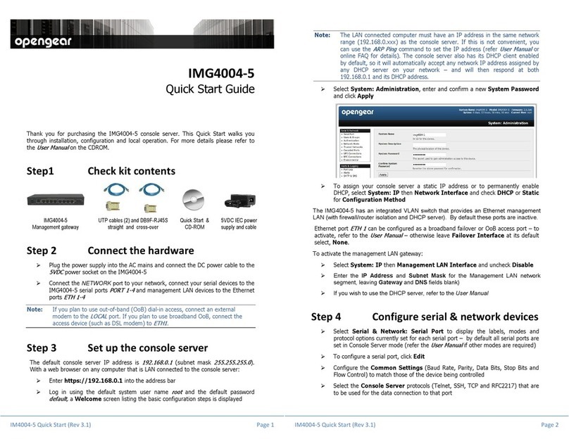
Opengear IMG4004-5 User manual

Opengear

Opengear IMG4004-5 User manual

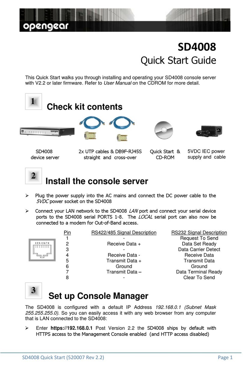
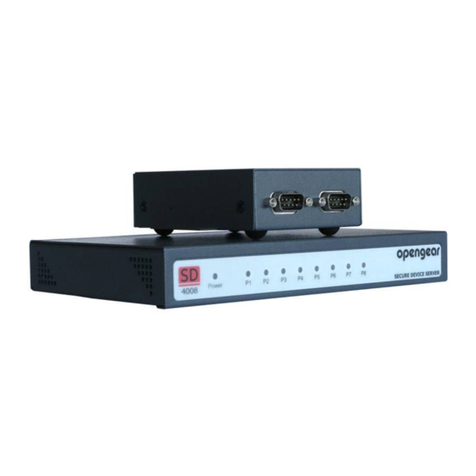
Opengear SD4008 User manual

Opengear

Opengear SD4008 User manual

Opengear SD4002 User manual

Opengear

Opengear SD4002 User manual

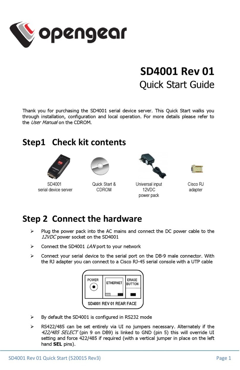
Opengear sd4001 User manual

Opengear

Opengear sd4001 User manual

Opengear ACM7000 User manual

Opengear

Opengear ACM7000 User manual

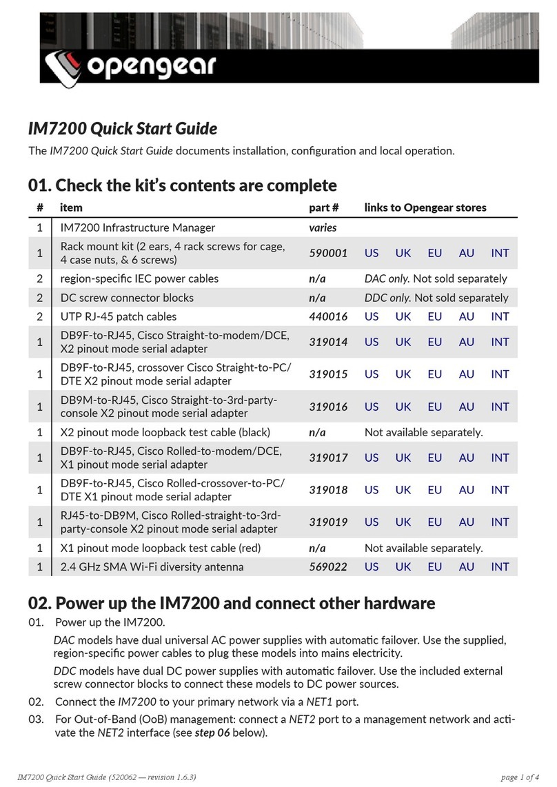
Opengear IM7200 User manual

Opengear

Opengear IM7200 User manual

Opengear SD4000 User manual

Opengear

Opengear SD4000 User manual

Opengear IM7216-2-24E User manual

Opengear

Opengear IM7216-2-24E User manual

Opengear CM4132 User manual

Opengear

Opengear CM4132 User manual

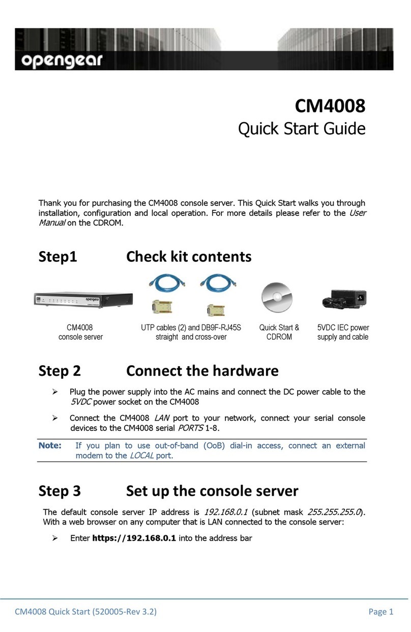
Opengear cm4008 User manual

Opengear

Opengear cm4008 User manual

Opengear SD4001 User manual

Opengear

Opengear SD4001 User manual

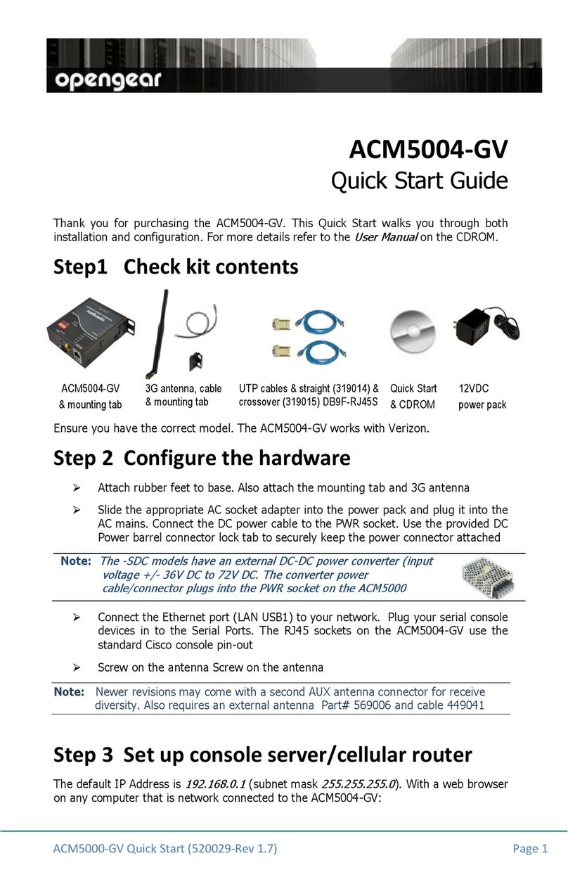
Opengear ACM5004-GV User manual

Opengear

Opengear ACM5004-GV User manual

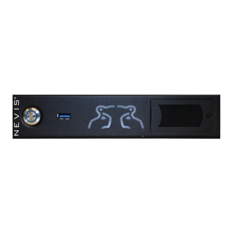
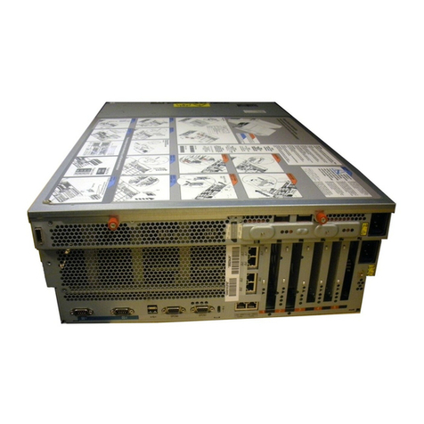
Popular Server manuals by other brands

Intel R2000WF series Service guide

Intel

Intel R2000WF series Service guide

Conceptronic Grab'n'GO CH3WNAS Quick installation guide

Conceptronic

Conceptronic Grab'n'GO CH3WNAS Quick installation guide

Fujitsu ETERNUS CS800 S5 user guide

Fujitsu

Fujitsu ETERNUS CS800 S5 user guide

ASCOM NISM2 installation guide

ASCOM

ASCOM NISM2 installation guide

Dell VxRail P670F Installation and service manual

Dell

Dell VxRail P670F Installation and service manual

HP T5720 - Compaq Thin Client supplementary guide

HP

HP T5720 - Compaq Thin Client supplementary guide

ASTRO U 100-230 operating manual

ASTRO

ASTRO U 100-230 operating manual

Dell PowerEdge R610 Getting started with

Dell

Dell PowerEdge R610 Getting started with

TROY Group TROY500 Series Installation and user guide

TROY Group

TROY Group TROY500 Series Installation and user guide

IEI Technology GRAND-C422-20D-H user manual

IEI Technology

IEI Technology GRAND-C422-20D-H user manual

NEC ExpEther-2S user guide

NEC

NEC ExpEther-2S user guide

Masterclock NTP100 -SERIES user manual

Masterclock

Masterclock NTP100 -SERIES user manual

Supermicro SUPERSERVER 5019S-M user manual

Supermicro

Supermicro SUPERSERVER 5019S-M user manual

Oracle Sun Fire X2270 M2 installation guide

Oracle

Oracle Sun Fire X2270 M2 installation guide

Lenovo 7X69 manual

Lenovo

Lenovo 7X69 manual

Kaleidescape Terra installation guide

Kaleidescape

Kaleidescape Terra installation guide

Oracle Netra SPARC S7-2 installation guide

Oracle

Oracle Netra SPARC S7-2 installation guide

Lantronix SecureBox SDS2100 user guide

Lantronix

Lantronix SecureBox SDS2100 user guide

manuals.online logo
manuals.online logoBrands
  • About & Mission
  • Contact us
  • Privacy Policy
  • Terms and Conditions

Copyright 2025 Manuals.Online. All Rights Reserved.