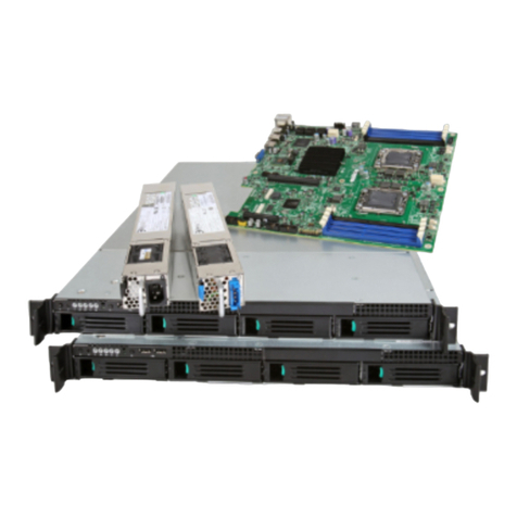
Intel®Server System R2000WF Product Family System Integration and Service Guide
10
2.9.2PCI Add-in Card Installation ......................................................................................................................................58
2.9.3Riser Card Bracket Installation ................................................................................................................................. 59
2.10PCIe* NVMe SSD Support...........................................................................................................................................60
2.10.1Installing the Intel® VROC Upgrade Key ............................................................................................................... 61
2.10.2Removing the Intel® VROC Upgrade Key..............................................................................................................61
2.10.3NVMe* Drive Population Rules for Intel® VROC ................................................................................................61
3.Configuration Options and Accessory Kit Integration and Service............................................................... 66
3.1Power Supply Module – Installation / Removal ................................................................................................67
3.1.12nd Power Supply Module Installation ..................................................................................................................67
3.1.2Power Supply Module Removal...............................................................................................................................67
3.1.3Power Cord Retention Strap Installation ............................................................................................................. 68
3.2ESRT2 SATA RAID 5 Upgrade Key – Installation / Removal......................................................................... 69
3.2.1ESRT2 SATA RAID 5 Upgrade Key Installation.................................................................................................. 69
3.2.2ESRT2 SATA RAID 5 Upgrade Key Removal .......................................................................................................69
3.3Intel®Remote Management Module 4 Lite Key – Installation / Removal................................................ 70
3.3.1Intel® RMM4 Lite Key Installation ............................................................................................................................70
3.3.2Intel® RMM4 Lite Key Removal .................................................................................................................................70
3.4Trusted Platform Module (TPM) Installation...................................................................................................... 71
3.5M.2 Memory Devices.....................................................................................................................................................71
3.5.1M.2 Installation................................................................................................................................................................71
3.5.2M.2 Removal..................................................................................................................................................................... 72
3.6OCP Expansion Module – Installation / Removal .............................................................................................73
3.6.1OCP Expansion Module Installation....................................................................................................................... 73
3.6.2OCP Expansion Module Removal............................................................................................................................74
3.7Intel® SAS RAID Module Installation/Removal...................................................................................................75
3.7.1Intel® SAS RAID Module Installation ...................................................................................................................... 75
3.7.2Intel® SAS RAID Module Removal............................................................................................................................75
3.8Intel®RAID Maintenance Free Backup Unit (RMFBU) – Mounting Bracket Installation ..................... 76
3.9Intel® Omni-Path IFT Carrier Accessory Kit Installation.................................................................................77
3.9.1Intel® Omni-path IFT Carrier Kit (iPC AWF1PFABKITM) – Installation .....................................................77
3.9.2Intel® Omni-path IFT Carrier Kit (iPC AWF1PFABKITP) – Installation ......................................................79
3.102 x 2.5” Rear Mount Backplane Module Accessory Kit (iPC- A2UREARHSDK1)...................................82
3.11Intel® SAS Expander Card Installation...................................................................................................................85
3.11.12.5” Front Drive Bay Support .................................................................................................................................... 85
3.11.23.5” Front Drive Bay Support .................................................................................................................................... 86
3.11.3Intel® RAID Expander Card Cabling Overview.................................................................................................... 86
3.12R2208WF Upgrade to 16 Drive Configuration................................................................................................... 87
3.1324 Drive Upgrade Option............................................................................................................................................88
4.System Software Updates and Configuration.................................................................................................... 93
4.1Updating the System Software Stack....................................................................................................................93
4.2Using the BIOS Setup Utility...................................................................................................................................... 93
4.2.1Entering BIOS Setup .....................................................................................................................................................93
