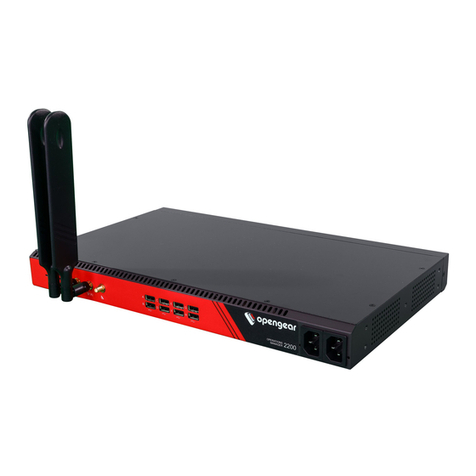
Opengear IP-KVM 1001 User manual

USER MANUAL
IP-KVM 1001
KVM over IP Switch
User Manual
Rev: 1.0
April 30th, 2009

KVM over IP User Manual Page 2 of 109
Copyright & Disclaimers
©Opengear Inc. 2009. All Rights Reserved.
In ormation in this document is subject to change without notice and does not represent a commitment on
the part o Opengear. Opengear provides this document “as is,” without warranty o any kind, expressed or
implied, including, but not limited to, the implied warranties o itness or merchantability or a particular
purpose.
Opengear may make improvements and/or changes in this manual or in the product(s) and/or the
program(s) described in this manual at any time. This product might include technical inaccuracies or
typographical errors. Changes are periodically made to the in ormation herein; these changes may be
incorporated in new editions o the publication.
For Warranty & Support in ormation please re er Appendix G
Notice to Users
Proper back-up systems and necessary sa ety devices should be utilized to protect against injury, death or
property damage due to system ailure. Such protection is the responsibility o the user.
This device is not approved or use as a li e-support or medical system.
Any changes or modi ications made to this device without the explicit approval or consent o Opengear will
void Opengear o any liability or responsibility o injury or loss caused by any mal unction.
This equipment is or indoor use and all the communication wirings are limited to inside o the building.
Ma ual Co ve tio s
This manual uses di erent onts and type aces to show speci ic actions:
Note Text presented like this indicates issues to take note of
Text presented like this highlights important issues and it is essential you read
and take head of these warnings
Text presented with an arrow head indent indicates an action you should take as part o the
procedure
Publishi g history
Date Revisio Update details
April 2009 1.0 Initial release document

KVM over IP User Manual Page 3 of 109
INDEX
1. Product Overview ............................................................................................................... 6
1.1 Introduction .................................................................................................................. 6
1.2 Main eatures ................................................................................................................ 6
2. I stallatio a d Start Up
..................................................................................................... 8
2.1 Package checklist ........................................................................................................... 8
2.2 Product Views ............................................................................................................... 8
2.3 LED indicators and Reset button .................................................................................. 10
2.4 System requirements ................................................................................................... 10
2.5 Hardware installation .................................................................................................. 11
2.6 Cabling the connection to stand-alone computers ....................................................... 11
2.6.1 Stand alone PS/2 ...................................................................................................... 12
2.6.2 Stand alone USB ....................................................................................................... 14
2.6.3 Cascaded connection ................................................................................................ 16
2.7 Cabling the connection to a multi-port KVM switch ..................................................... 17
2.8 When the server is up and running .............................................................................. 19
2.9 When the server is dead .............................................................................................. 19
3. Co figuratio .................................................................................................................... 20
3.1 Initial IP con iguration using psetup ............................................................................. 20
3.1.1 Reset the Super User password ............................................................................. 20
3.1.2 Set up a ixed IP ..................................................................................................... 21
3.1.3 Enable DHCP.......................................................................................................... 21
3.2 Initial IP con iguration using a web browser ................................................................ 23
3.3 Initial IP con iguration using the serial console ............................................................ 24
3.4 Keyboard, mouse and video con iguration ................................................................... 25
3.4.1 IP-KVM keyboard settings ...................................................................................... 25
3.4.2 Remote Mouse Settings
......................................................................................... 25
3.4.3 Automatic mouse speed and mouse synchronization ............................................ 26
3.4.4 Host system mouse settings .................................................................................. 26
3.4.5 Single and Double Mouse Mode ............................................................................ 27
3.4.6 Recommended Mouse Settings ............................................................................. 27
3.4.7 Video Modes ......................................................................................................... 27
4. Usage ................................................................................................................................ 28
4.1 Prerequisites ............................................................................................................... 28
4.1.1 Browser ................................................................................................................. 28
4.2 Logging in and out ....................................................................................................... 29
4.2.1 Log in to the IP-KVM .............................................................................................. 29
4.2.2 Log out rom the IP-KVM ....................................................................................... 31
4.3 The Remote Console .................................................................................................... 32
4.3.1 Main Window o Remote Console ......................................................................... 32
4.3.2 Control Bar o Remote Console .............................................................................. 33
4.3.3 Status Line o Remote Console .............................................................................. 43
5. Me u Optio s ................................................................................................................... 44
5.1 Remote Control ........................................................................................................... 44
5.1.1 KVM Console ......................................................................................................... 45
5.1.2 Telnet/SSH Console................................................................................................ 45
5.2 Virtual Media .............................................................................................................. 48
5.2.1 Drive Redirection ................................................................................................... 49
5.2.2 Virtual Drive .......................................................................................................... 50
5.2.3 CD/DVD Image....................................................................................................... 51
5.2.4 Floppy Disk ............................................................................................................ 56
5.2.5 Creating an Image.................................................................................................. 58
5.2.5.1 Creating a Floppy Image ............................................................................ 58
5.2.5.2 Creating a CD/DVD ISO Image ................................................................... 59

KVM over IP User Manual Page 4 of 109
5.2.6 Making a Drive Redirection .................................................................................... 60
5.3 User Management ....................................................................................................... 64
5.3.1 Change Password .................................................................................................. 64
5.3.2 Users and Groups .................................................................................................. 65
5.4 KVM Settings ............................................................................................................... 66
5.4.1 User Console ......................................................................................................... 66
5.4.2 Keyboard/Mouse ................................................................................................... 70
5.4.3 Video ..................................................................................................................... 71
5.5 Device Settings ............................................................................................................ 72
5.5.1 Network ................................................................................................................ 72
5.5.2 Dynamic DNS
......................................................................................................... 75
5.5.3 Security ................................................................................................................. 77
5.5.4 Certi icate .............................................................................................................. 79
5.5.5 Serial Port .............................................................................................................. 82
5.5.6 Date / Time ........................................................................................................... 84
5.5.7 Event Log ............................................................................................................... 86
5.5.8 Authentication....................................................................................................... 88
5.5.9 USB ....................................................................................................................... 91
5.5.10 Con ig File .......................................................................................................... 91
5.5.11 Authentication ................................................................................................... 92
5.6 Maintenance ............................................................................................................... 94
5.6.1 Device In ormation ................................................................................................ 94
5.6.2 Event log ............................................................................................................... 95
5.6.3 Update Firmware ................................................................................................... 96
5.6.4 Unit Reset .............................................................................................................. 98
5.6.5 Reset to Factory De aults ....................................................................................... 99
6. Adde dum ...................................................................................................................... 102
A. Key Codes ........................................................................................................................ 102
B. Video Modes ................................................................................................................... 103
C. User Role Permissions ...................................................................................................... 103
D. Bandwidth Consumption ................................................................................................. 104
E. Pin-outs o RJ45-DB9F Cable ............................................................................................ 104
F. TCP/UDP Port Numbers
.................................................................................................... 105
G. Protocol Glossary ............................................................................................................ 105
H. Regulation In ormation .................................................................................................... 106
I. Service and warranty ........................................................................................................ 107

KVM over IP User Manual Page 5 of 109
F i g u r e s
Figure 2-1 Product View ............................................................................................................... 9
Figure 2-2 Panel View ................................................................................................................. 10
Figure 2-3 3-in-1 Integrated Adapting Local Cable ...................................................................... 10
Figure 2-4 Serial Cable ................................................................................................................ 10
Figure 2-5 Cable Connections (stand-alone, PS/2) ...................................................................... 13
Figure 2-6 Cable Connections (stand-alone, USB) ....................................................................... 15
Figure 2-7 Cable Connections (stand-alone, PS/2) ...................................................................... 16
Figure 2-8 Cable Connections (with a Multi-port KVM Switch).................................................... 18
Figure 4-1 The Internet Explorer displaying the encryption key length ....................................... 29
Figure 4-2 Remote Console Control Bar ...................................................................................... 33
Figure 4-3 Remote Console Options Menu ................................................................................. 34
Figure 4-4 Remote Console Exclusive Mode ............................................................................... 35
Figure 4-5 Remote Console Options Menu:Scaling ..................................................................... 36
Figure 4-6 Remote Console Options Menu:Cursor ...................................................................... 37
Figure 4-7 Video Settings Panel .................................................................................................. 38
Figure 4-8 So t Keyboard ............................................................................................................ 39
Figure 4-9 So t Keyboard Mapping ............................................................................................. 39
Figure 4-10 Remote Console Con irmation Dialog ...................................................................... 40
Figure 4-11 Encoding Compression ............................................................................................ 41
Figure 4-12 Prede ined Compression.......................................................................................... 42
Figure 4-13 Lossy Compression .................................................................................................. 42
Figure 4-14 Encoding Color depth .............................................................................................. 43
Figure 4-15 Status line ................................................................................................................ 43
Figure 4-16 Status line trans er rate ........................................................................................... 43
Figure 5-1 KVM Console ............................................................................................................. 45
Figure 5-2 Telnet Console ........................................................................................................... 47
Figure 5-3 Options o Drive Redirection...................................................................................... 50
Figure 5-4 USB mass storage option ........................................................................................... 51
Figure 5-5 Virtual Media - CD-ROM Image .................................................................................. 51
Figure 5-6 Explorer Context Menu .............................................................................................. 53
Figure 5-7 Share Con iguration Dialog ........................................................................................ 54
Figure 5-8 Virtual Media - Floppy Disk ........................................................................................ 56
Figure 5-9 RawWrite or Windows selection dialog .................................................................... 58
Figure 5-10 Nero selection dialog ............................................................................................... 59
Figure 5-11 Built-in Java Drive Redirection ................................................................................. 60
Figure 5-12 Setting Password ..................................................................................................... 64
Figure 5-13 User Console Setting ................................................................................................ 68
Figure 5-14 Keyboard and Mouse Settings ................................................................................. 70
Figure 5-15 Video Settings .......................................................................................................... 71
Figure 5-16 Network Settings ..................................................................................................... 73
Figure 5-17 Dynamic DNS ........................................................................................................... 75
Figure 5-18 Dynamic DNS Scenario ............................................................................................. 76
Figure 5-19 Device Security ........................................................................................................ 77
Figure 5-20 Chain Rules o IP Filtering ........................................................................................ 78
Figure 5-21 IP Filter Settings ....................................................................................................... 79
Figure 5-22 Certi icate Settings .................................................................................................. 80
Figure 5-23 SSL Certi icate Upload .............................................................................................. 82
Figure 5-24 CSR string ................................................................................................................ 82
Figure 5-25 Serial Port ................................................................................................................ 83
Figure 5-26 Date / Time .............................................................................................................. 85
Figure 5-27 Event Log ................................................................................................................. 86
Figure 5-28 Device In ormation .................................................................................................. 94
Figure 5-29 Connected Users ...................................................................................................... 95
Figure 5-30 Event Log List ........................................................................................................... 95
Figure 5-31 Update Firmware ..................................................................................................... 96
Figure 5-32 Unit Reset ................................................................................................................ 99

KVM over IP User Manual Page 6 of 109
1. Product Overview
1.1 Itroductio
Opengear’s KVM-over-IP switch (re erred to generically in this manual as the IP-KVM) redirects local
keyboard, mouse and video data to a remote administration console. It allows you to control one
or many computers locally at the server site or remotely via the Internet using a standard browser.
You can securely gain BIOS level access to systems or maintenance, support, or ailure recovery
over the Internet. Communication is secured via SSL authentication and encryption. The IP-KVM
can also be used in conjunction with a KVM switch or multiple-server access.
The IP-KVM provides convenient remote KVM access and control via LAN or Internet. It captures,
digitizes and compresses video signal and transmits it with keyboard and mouse signals to and
rom a remote computer. IP-KVM provides a non-intrusive solution or remote access and control.
Remote access and control so tware runs on its embedded processor only but not on
mission-critical servers, so that there is no inter erence with server operation or impact on
network per ormance.
1.2 Mai features
• Manage servers around the world
• Remote KVM (keyboard, video, and mouse) access over IP network or over a modem link
• Local console port or direct analogous access to KVM switch
• Combo (PS2 + USB) Local Console inter aces
• Dual LAN port or Remote Console and easy cascaded wiring
• Dual USB port or Local Console
• Full control under any OS at BIOS level, during boot, or at Blue Screens
• No additional so tware necessary on client console side
• Remote mass storage control and redirection
• Remote control over Java-enabled browsers
• SSL Secure access through certi icate authentication and data encryption
• SSL 256-bit encryption o all transmitted data
• RSA 2048-bit encryption
• Auto-optimize the rame rate and video quality according to the bandwidth availability
• Automatically senses video resolution or best possible screen capture
• High-per ormance mouse tracking and synchronization
• Interwork with most o KVM switches

KVM over IP User Manual Page 7 of 109
• Firmware update via web inter ace
• Rack mountable
Feature Descriptio
Target Server Side
1x Attached 3-in-1 integrated cable and K/V/M connectors (HDDB15 male plus two
mini din 6-pin PS/2 connectors)
1x USB 2.0 mini receptacle
1x RJ-45 Serial Port
Local Co sole Side 1x 3-in-1 VGA connector (HDDB15 emale)
2x USB type-A connectors
Remote Co sole Side 2x Standard RJ-45 Connectors (LAN ports)
LED I dicators 2x LEDs: Power (red), Ready (green)
Push Butto 1x Reset push button
Video Resolutio up to 2048 x 1536 @60Hz (Local Console)
up to 1600 x 1200 @60Hz (Remote Console)
Protocols TCP, IP, ARP, ICMP, HTTP/HTTPS, SSL, Telnet, DHCP, PPP, SMTP, NTP, DDNS
Security
AES 256-bit encryption or all transmitted data
RSA 2048-bit encryption or authentication
SSHv2
Authe ticatio SSL / Certi icate, RADIUS, LDAP
Virtual Media Floppy/CD/DVD/USB/HD drive redirection
Floppy/CD/DVD/ISO Image redirection
DC Power 12VDC, 1A
Operatio Temperature 0 ~ 50 ℃ (32 ~ 122 ℉)
Humidity 0~80% RH
Housi g Metal
Dime sio (mm) 103 x 87 x 28.5
Weight 1000g

KVM over IP User Manual Page 8 of 109
2. I stallatio a d Start Up
I troductio
This chapter overviews the general installation and con iguration o your IP-KVM and steps through
in detail the physical installation and connection to controlled devices
2.1 Ge eral i stallatio a d co figuratio steps
Step 1 Check kit contents (re er Chapter 2.2)
Step 2 IP-KVM installation and connection to the target server and network (re er Chapter
2.5 - 2.7)
Step 3 Con igure the IP-KVM network settings (re er Chapter 3.1 - 3.3)
Step 4 Con iguring the KVM settings or the Target Server and IP-KVM (re er Chapter 3.4)
2.2 Package checklist
The IP-KVM package consists o the ollowings items:
The IP-KVM unit
CD-ROM (so tware utilities and user manual)
Quick Start Guide
DC power supply adapter
3-in-1 Integrated Adapting Local Cable
USB A-mini cable
Serial cable (RJ45 to DB9F)
Rack mounting kit (with brackets and screws)
Footpads set
2.3 Product Views
The IP-KVM has an attached 3-in-1 Integrated Host Cable to simpli y cable connection. Similarly the
dual LAN ports provides lexibility o cascaded wiring and the palm size orm actor enables lexible
installation.

Figure 2-1 Product View
Power Jack
3-in-1 Integrated KVM Ca le (Host)
Serial Port
3-in-
1 Integrated
Adapting Ca le for
Local Console
Dual USB
2.0 Port for
Local Console
or general
purpose USB devices
Dual LAN Port for
Local Console
USB (Host)
Reset
LEDs

KVM over IP User Manual Page 10 of 109
Figure 2-2 Pa el View
Figure 2-3 3-i -1 I tegrated Adapti g Local Cable
Figure 2-4 Serial Cable
2.4 LED i dicators a d Reset butto
LED I dicatio
Power RED – on when power applied
Ready Gree -- blinking per second when system is ready
<Ether et>
Ether et Li k/Act/10/100Mbps:
Ora ge -- 10BaseT Ethernet connection established
Gree -- 100BaseT Ethernet connection established
Blinking: data in activity
ON: no data in activity and link connected
A recessed RESET button is located on the rear panel. Press the button to reboot the
IP-KVM unit
2.5 System requireme ts
Hardware
Item Descriptio
Local Host side One Computer or Server or the console port o the KVM switch

KVM over IP User Manual Page 11 of 109
Local console side One PS/2 or USB Keyboard and Mouse, and one Monitor
Remote Console side One Computer or Multiple Computers are linked into the network
Software
Item Descriptio
Local Host side <No additional so tware necessary>
Remote Console side
(1) Java Runtime Environment (see Note)
(2) Browser: Microso t Internet Explorer (v6.0 or above), Netscape,
Mozilla, Sa ari, Fire ox, Avant, World, Opera, and others.
Note The Remote Console rowser needs to JRE (Java Runtime Environment) v5.0 (version 1.5) or a ove.
You can get the Java Software from the we site http://www.java.com/en/download/.
It’s recommended to install newer Java version (e.g. version 6 update 11 or a ove) for etter
performance.
2.6 Hardware i stallatio
The IP-KVM can be placed on the desktop or rack mounted on a 19”/1U rack:
Screw the mounting brackets into the side o the unit at the ront, as shown below
Slide the unit into the rack and secure it to the rack
2.7 Cabli g the co ectio to sta d-alo e computers
When connecting cables ensure the IP-
KVM and host computer are powered off

KVM over IP User Manual Page 12 of 109
2.6.1 Sta d alo e PS/2
To cable connect to a stand-alone host computer with PS/2 style keyboard and mouse:
Connect the VGA and PS/2 connectors o the attached 3-in-1 Integrated Host Cable to the
Host computer
Connect the 3-in-1 Integrated Adapting Cable to the Local DB-15 connector o IP-KVM
Connect the monitor to the Adapting Cable
Connect the keyboard to the Adapting Cable
Connect the mouse to the Adapting Cable
Connect one end o Ethernet cable to LAN1 or LAN 2 jack o IP-KVM, and the other end to
the Remote Console computer

KVM over IP User Manual Page 13 of 109
Figure 2-5 Cable Co ectio s (sta d-alo e, PS/2)

KVM over IP User Manual Page 14 of 109
The IP-KVM cabling should now be connected to the Host and Console devices as shown in Figure
2.5 above. Leave the Serial inter ace open or now. Optionally connect the USB connectors o USB
A-mini cable to the Host computer and the IP-KVM ( or remote mass storage control).
Apply power to the Host and IP-KVM. It will take about 60 seconds to complete its startup
processes and enter normal running state
2.6.2 Sta d alo e USB
To cable connect to a stand-alone host computer with USB keyboard /mouse:
Connect the VGA o the attached 3-in-1 Integrated Host Cable to the Host computer
Connect the USB connectors o USB A-mini cable to the host computer and the IP-KVM
module while or remote mass storage control
Connect the 3-in-1 Integrated Adapting Cable to the Local DB-15 connector o IP-KVM
Connect the monitor to the Adapting Cable
Connect the USB keyboard to the USB2 or USB1 connector
Connect the USB mouse to the USB1 or USB2 connector
Connect one end o Ethernet cable to LAN1 or LAN 2 jack o IP-KVM, and the other end to
the Remote Console computer (over your IP network)
Figure 2.6 below depicts the installation cable connections:

KVM over IP User Manual Page 15 of 109
Figure 2-6 Cable Co ectio s (sta d-alo e, USB)

KVM over IP User Manual Page 16 of 109
2.6.3 Cascaded co ectio
The IP-KVM has a built-in Ethernet hub so it is simple to cascade multiple IP-KVM devices to
control multiple host computers:
Figure 2-7 Cable Co ectio s (sta d-alo e, PS/2)
Install cable connections between each stand-alone IP-KVM and Host computer (as
described in 2.6.1 and 2.6.2)

KVM over IP User Manual Page 17 of 109
With straight or cross-over Ethernet cables interconnect the IP-KVM devices using LAN1 or
LAN2 sockets
Connect one end o the Ethernet cable to LAN1 or LAN 2 jack o one o the IP-KVM devices
and the other end to the Remote Console computer
2.8 Cabli g the co ectio to a multi-port KVM switch
As well as connecting to a standalone computer the IP-KVM host side can alternately be connected
to a multi-port KVM switch.
The installation procedures are as or stand-alone computer, except that the host signals are
connected to the PS/2 Local Co sole o the KVM Switch.
Figure 2.8 below depicts the cable connections:

KVM over IP User Manual Page 18 of 109
Figure 2-8 Cable Co ectio s (with a Multi-port KVM Switch)

KVM over IP User Manual Page 19 of 109
2.9 Whe the server is up a d ru i g
The IP-KVM gives you a ull control over the remote server. The Management Console allows you
to access the remote server’s graphics, keyboard and mouse and to send special commands to the
server. You can also per orm periodic maintenance o the server. Using the Console Redirection
Service, you are able to do the ollowing:
- Reboot the system
- Watch the boot process.
- Boot the system rom a separate partition to load the diagnostic environment.
- Run special diagnostic programs
2.10 Whe the server is dead
Obviously ixing hardware de ects is not possible through a remote management device.
Nevertheless IP-KVM gives the administrator valuable in ormation about the type o a hardware
ailure that has occurred so they can initiate appropriate recovery action:
Type of failure Detected by
Hard disk ailure Console screen, CMOS set-up in ormation
Power cable detached, power supply
ailure
Server remains in power o state a ter power on
command has been given.
CPU Controller, main board ailure. Power supply is on, but there is no video output.
CPU an ailure By server speci ic management so tware
RAM ailure Boot-Sequence on boot console

KVM over IP User Manual Page 20 of 109
3. Co figuratio
I troductio
This chapter provides step-by-step instructions or the initial network con iguration and the keyboard,
video and mouse communications settings. The IP-KVM can be set up:
Over the network using the psetup tool
Over the network using a web browser
Over a serial connection using a terminal (emulator)
3.1 I itial IP co figuratio usi g psetup
The actory de ault settings or the IP-KVM unit are:
DHCP: Disable
De ault IP address: 192.168.0.70
De ault Net Mask: 255.255.255.0
I this initial con iguration does not meet your local requirements you can use the psetup setup
tool to change the con iguration to suit your needs. You can be ind psetup on your IP-KVM
CD-ROM. The psetup tool can locate all the IP-KVM units on your IP network and set their network
con iguration (IP address, subnet mask, DHCP etc).
3.1.1 Reset the Super User password
Make sure to change the super user password immediately after you ha e
installed and accessed your IP-KVM for the first time. Not changing this
password for the super user is a se ere security risk and might result in
unauthorized access to the IP-KVM and to the host system
Click Refresh Devices and psetup will detect any network connected IP-KVM devices and
display them by their MAC addresses
You can click Query Device and it will show the current IP con iguration o the selected
MAC address device (i.e. IP address 192.168.0.70)
Enter the Super User login name. The initial name is super with all lower case characters
Enter the current Super User password. This initial value is pass again all lower case
Enter a New Super User password and re-type the New password con irmation
Other manuals for IP-KVM 1001
1
Other Opengear Switch manuals
Popular Switch manuals by other brands

Cisco
Cisco 6503 - Catalyst Firewall Security Sys installation guide

Hisense
Hisense HCHM-N04X installation manual

Huawei
Huawei MA5821 installation guide

Extron electronics
Extron electronics PVS 305SA Setup guide

Ocean Matrix
Ocean Matrix OMX-DEM100 instruction manual

Optical Systems
Optical Systems OSD2251P SERIES Operator's manual

Accton Technology
Accton Technology EH3008D Quick installation guide

IPGARD
IPGARD SDVN-2D user manual

MuxLab
MuxLab Profidigital 500445 installation guide

SP Controls
SP Controls SP-SW1900-HD user guide

Perle
Perle IDS-409F quick start guide

Generac Power Systems
Generac Power Systems RXSW200A3F owner's manual