Opitec Thermo fan 105.434 User manual

1
E105434#1
105.434
Thermo fan
Important Notice:
Beware of fire, never leave a
burning candle unattended!!
Please Note
The OPITEC range of projects is not inten-
ded as play toys for young children.They are
teaching aids for young people learning the
skills of Craft, Design and Technolo- gy.
These projects should only be undertaken
and tested with the guidance of a fully qua-
lified adult. The finished projects are not sui-
table to give to children under 3 years old.
Some parts can be swallowed. Dan- ger of
suffocation!

1. Product information:
Article: electro-mechaniacal model
Use: in Design Technology Key stage 3
2. Material Information:
2.1. Material: Pine (confirous), soft wood
wood should be relativly dry before working
Working: Pine can be sawn, planed, shaped and drilled
mark out with measurements or use paper patterns
Joining: screws
Finish: wax (liquid or solid)
wood varnish (undercoat/clear)
stain (water soluable then varnish)
2.2. Material: Zinc sheet
Working: cut with metal shears / tin snips
fold using a vice
mark out by measurement or use patterns
drilling;
Joining: screws
Finish: none necessary, could be sprayed with clear varnish
2.3. Material: holed metal strip (zinc plated)
Working: cut with a Hacksaw
Bend using a vice
mark out with a scriber
Joining: use screws
Finish: no special finish necessary
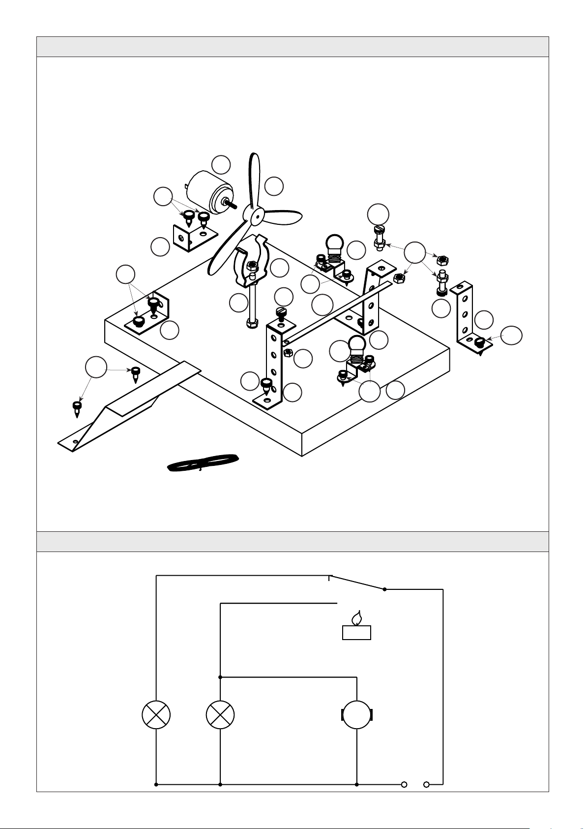
2.3. Electro components:
Bulb holder: with 2 soldering tabs
suitable for E10 bulb
Bulb: 3.5 volts, 0,2A to fit E10 holder
Insulated wire: single strip wire 0.5mm
Bi metal strip: a fusion of two different metals, with different expansions rates
Motor: DC 1.5-4.5 Volt
2E105434#1

3. Tools:
Saws: use a hacksaw for the holed metal strip
Note! hold the work in a vice
make sure that the blade is inserted with the teeth
facing forward
Filing: choose a suitable grade of file
Note! files only cut on the foward stroke
Finishing: use a glasspaper and block for all flat surfaces
and loose paper for curves;
Drilling: use a handrill or electric pillar drill
Note! take care when drilling, wear safety glasses, tie
all long hair back, remove rings and jewellery. Wear an
apron and clamp the work to be drilled safely
Bending: use a vice or folding irons
Note! soft jaws are neede!
Cutting: use side cutters to strip the plastic fom the insulated wire
Tin snips for cutting the metal sheet
Soldering: for soldering use a 15-30Wat fine tipped iron, in conjunction with flux
Note! the soldering iron tip becomes very hot
If you use electronic solder the flux is in the core!
3
E105434#1

4. Parts list
Description Material Quantity Diagram Size
Base Wood 1 15 x 150 x 200 mm
Holder Metal 2 1 x 15 x 255 mm
Shield metal 1 0.29 x 100 x 100 mm
Fan
Motor 1 1.5V -4.5Volts
Propellor 1 115mm dia
Spring clip 1 23 - 27 mm
Set screw 1 M4 x 50/60 mm
Nut 1 M4
Washer 2 M4
Electro components
Bulb holder metal 2 E10
Bulb 3.5 V/0.2A red 1 E10
3.5 V/0.2A green 1 E10
Insulated wire 500 mm 2 500 mm
Bi-metal strip Typ 206-1 1 0.4 x 4.7 x 200mm
Sundries
Washers 12 M4
Nuts 4 M4
Set screws 2 M4 x 16 mm
Nut 1 M3
Set screw 1 M3 x 6 mm
Screws 6 2.9 x 9.5 mm
Screws 12 3.9 x 9.5 mm
Candle 1 32 mm dia
4E105434#1
1
2
3
4
6
7
8
9
10
11
12
13
14
15
16
17
18
19
20
21
22

5. Exploded diagram
6. Wiring diagram
5
E105434#1
Scale 1 : 2
+
M
-
4.5V
Red bulb
Bi metal
Green
bulb
5
6
7
2
2
21
21
21
21
20
2
2
2
1
10
14
19
18
17
17
16
20
20
10
4

7. Planning overview
7.1 Planning and making the base
7.2 Making the supports
7.3 Assembling the bi-metal strip
7.4 Planning and bending the shield
7.5 Assembling the small parts
7.6 Wiring the circuit
7.7 Testing the circuit
7.1. Planning and making the base
7.1.1 Mark out or trace the pattern (page 13) on to the base 10-20 x 150 x 200mm
7.1.2 Mark out the holes for the screws, approx 5mm deep with a bradawl using a bradawl
7.1.3 Drill the 4.5mm dia hole through the base as shown, turn the base over and counter drill on the same spot a
10mm dia hole, 5-15mm deep blind hole, depending on the thickness of the base
Note: do not drill the blind hole (underneath the base) all the way through
7.2. Making the supports
7.2.1 From the holed metal strip (2) saw off a 2 pieces each 4 holes long (approx 45mm) and file the ends smooth
Bend both pieces of metal as shown Bendin pattern
Tip: use protective vice jaws!
6E105434#1
80
80
Ø 4,5
Ø 4,5
15
20
Ø 10
Ø 10
15
90°
45
Bend here
Bending pattern
1
2

7.2.2 From the holed metal strip (2) mark out and saw one piece 6holes long (approx 85mm) and clean up the ends
with a file. Bend the contact strip for the bi-metal strip as shown in the diagram
Tip: use protective soft jaws in the vice !
7.2.3 From the holed metal strip (2) cut a piece 6 holes long (approx 85mm) Then bend it as shown to form the
contact strip for the red bulb and motor
Tip: use protective soft jaws in the vice !
7.2.4 From the holed metal strip (2) saw a piece with 7 holes (approx 105mm long) clean up the ends. This will be
the contact strip for the green bulb
Tip: use protective soft jaws in the vice
7
E105434#1
15 15
90
90°
90°
30
85
10
90°
90°
15
105
30 35
90°
99°
171°
Bend here
Bend here
Bend here
Bending pattern
Bending pattern
Bending pattern
2
2
2
ca. 170°
ca. 98°

7.3. Making the bi-metal strip
7.3.1 Shorten the bi-metal strip to 110mm long and drill the hole in one end
Note! remember the safety rules when drilling
7.4. Planning and bending the shield
7.4.1 Mark out the measurements as shown on to the metal sheet, drill the holes and clean up the edges with a
file
Tip: use protective soft jaws in the vice when bending metal sheet
8E105434#1
Ø 3
5
110
8
15
80
90
10
70
80
121°
121°
Ø 3
Ø 3
bending pattern
14
3
ca. 120°
ca. 120°

7.5. Assembling the parts
7.5.1 The holder for the fan is made up from the parts as shown
7.5.2 Screw the two battery contact holed metal strips (made in step 7.2.1) to the base (1) as shown
Tip: do not insert the screws too tightly. They can be fully tightened after the cable has been added
9
E105434#1
6
1
7
9
8

7.5.3 Fix the bi-metal strip (printed side down) to its holder with a nut and screw (19) and (18) and then mount (21)
the holder, made in step 7.2.2, to the base
Note: do not tighten the screw (21) fully until the wiring has been completed
7.5.4 Mount the sets screws and M4 nuts on the contacts holders made made in steps 7.2.4 amd 7.2.4 as shown in
the diagram
Finally screw the metal strip to the base, adding the two bulb holders at the same time, using screws (20 and
21)
Note: do not tighten the screws fully until the wiring is complete also the contact strip for the green light
may have to be bent slightly
10 E105434#1
2
printed side
17
17
16
20 21
20
20
21

7.5.5 Screw (20) the fan shield to the base as shown
Push the propellor (5) on the motor shaft and insert the motor (4) into the spring clip
7.6. Wiring the circuit
7.6.1 For the motor connection take 2 lengths of different colour cable 100mm long and remove the insulation from
both ends. Twist the cables around a pencil to make them curly and solder one end of each cable to the
motor
The other ends are clamped under the screws as shown on the plan
Tip watch for the polarity of the motor!
the air should blow in the direction of the bi-metal strip
7.6.2 Insert small screws and washers into the remaining holes on the base
Note: do not fully tighten them yet
7.6.3 Complete the remainder of the wiring as shown on the plan
Note: solder the cable to the connections on the bulb holders
11
E105434#1
+ - Pol - - Pol

7.7. Testing the circuit
7.7.1 Screw the red and green bulbs into the holders
7.7.2 Set the distance between the bi-metal strip and the contacts on the metal strips for the red and green lights.
The contact screw for the green light should be adjusted so that it touches the bi- metal strip and the other
screw so that there is a gap of 2mm.(step 7.5.4)
7.7.3 Place the battery onto the correct contacts on the base
Note: Be careful of the polarity
Now the green bulb should light
Light the candle under the bi-metal strip
Note: Never leave a lit candle unattended
In a relatively short time the bi-metal strip will bend towards the contact for the red bulb and the fan will start
up As the fan starts to cool the bi-metal strip it will bend back again.The green bulb will light up and the fan
switch off. The flame warms up the bi-metal and the cycle will start up again
Probelems: Cause:
- Bi-metal strip does not switch - wrong way up,print showing on top
- Motor stays on too long - the rotation is wrong
- The green or red bulb does not light - Bad conection between the contact set
screws and bi-metal strip
- Fan blows the candle out - Tea light in the wrong position behind the
shield
12 E105434#1

13
D105434#1
Driling pattern
Scale 1 : 1
Contact strip
+
Contact strip
-
Battery
shield
Holder strip
for bimetal
Bulb holder,
red bulb
Contact strip,
red bulb
Bulb holder,
green bulb
Contact strip
green bulb
cable
cable
Blind hole in the base
shown in section
cable
cable
cable
Table of contents
Popular Educational Equipment manuals by other brands

Cleaver Scientific
Cleaver Scientific runVIEW Real-Time instruction manual

Copernicus
Copernicus LLS100 Assembly guide

SeaPerch
SeaPerch ROV Construction manual

Simulaids
Simulaids RANDY 9000 Instruction and Care Manual

Quanser
Quanser QNET Physics and Dynamics user manual

Rompa
Rompa Rainbow Bumpas with Vibration manual