Opt Lasers Grav PLH3D-6W Series Quick start guide

Copyright © 2020 by Tomorrow's Sys tem Sp. z o.o. Al l Rights Res erved.
CNC Machines Laser Upgrade Instructions
This part of the documentation is connected with popular CNC machines Laser Upgrades.
Basically, with the help of the PLH3D-CNC Adapter, it is possible to connect the laser head to almost
any CNC machine and turn it into laser engraver. A very important thing besides the connection is G-
Code generating. It differs from the standard G-Code. The laser needs to be switched off during the
idle movement while spindle can be left rotating. The most similar thing in Laser and Spindle G-code
is the power and the rotation speed. PWM signal is controlling the rotation speed of the spindle
while the same signal can be used to control the laser power. Usually, it is done with S0 - S255
command but different CNC Software and Controllers are using different values, for example, S0 -
S1000.

Support and Manua ls
2 / 26
LEAD/WorkBee CNC Laser Upgrade Setup
Guide for PLH3D-6W-Series Laser Heads
Contact and Shipping: Company Information:
Tomorrow's System Sp. z o.o. Tomorrow's System Sp. z o.o.
Okulickiego 7/9 hala G39 Pułaskiego 125/35
05-500 Piaseczno 15-337 Białystok
Poland Poland
tel.: +48 515 180 752 NIP: PL5423238556
e-mail:
contact@optlasers.com
REGON: 200866868

Support and Manua ls
3 / 26
Introduction
The OpenBuilds LEAD CNC is a machine with greatly enhanced functionalities and a vast range of
applications. Thanks to its build, it is very rigid and therefore very accurate. It can be used by
amateurs, hobbyists, and professionals alike for processing various types of soft and hard materials at
scale and with an even higher degree of precision than ever before. Extending the machine by
adding a quality laser head to it, such as Opt Lasers PLH3D-6W-Series laser head, enables
unmatched fast precision engraving and cutting of various types of materials.
The OpenBuilds LEAD CNC machine is available in two versions:
§OpenBuilds LEAD CNC Machine 1515 (60" x 60")
§OpenBuilds LEAD CNC Machine 1010 (40" x 40")
The Z-axis position of the cutting and engraving laser head can be changed at will to enable this
machine to efficiently cut and engrave taller specimens.
The OpenBuilds LEAD CNC machine prices range from $1300 to $1800 depending on the version of
choice. With the amazing material processing capabilities it offers, it is definitely worth the price.
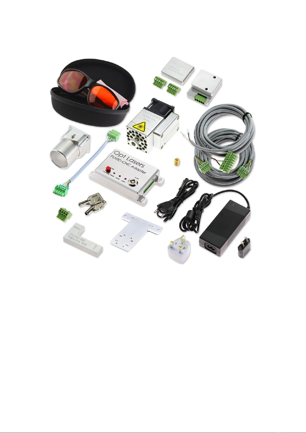
The PLH3D-6W-XF Laser OpenBuilds LEAD CNC Upgrade Kit includes a high-power engraving laser
head equipped with thermal protection and a professional high-speed driver. Its design ensures that
function as an air nozzle, protecting the lens from dirt while cooling the laser head at the same time.
Attaching a magnetic nozzle makes it even more convenient to use.
The laser head, combined with the LEAD CNC machine and the BlackBox controller, allows you to cut
or engrave materials such as rubber, wood, paper, leather, plastic, cardstock, and many others.
Thanks to its PWM/TTL power modulation modes support,
or change the output power between consecutive runs. High-speed modulation (the PLH3D-6W-XF
laser head can handle frequencies up to 100 kHz) allows for a high movement rate during engraving,
even when engraving sophisticated patterns. This rate is more than enough to take advantage of the
Using the PLH3D-CNC Adapter guarantees reliable and safe work via overcurrent protection, an
independent power supply, a key switch, and an arm button. Furthermore, using the Magnetic
Docking station to mount the laser head on the LEAD CNC machine reduces the time needed to
mount/dismount and to secure the laser head to just a few seconds (while it requires no
additional tools). Moreover, it enables a person to operate the laser without the need for
disassembling the spindle. This module operates a brand new NUBM44 450nm diode (capable of
emitti ng up to 6 Watts of power), which is the strongest blue laser diode that is available on the
market. The lifetime of this laser diode amounts to 10 000 hours according to the manufacturer.

Support and Manua ls
4 / 26
Included Parts

Support and Manua ls
5 / 26
Laser Safety
Only person with specialized training and appropriate laser safety knowledge
can use and maintain the laser head. The laser head operator must be aware of
laser radiation hazard.
While laser head is operating protection Laser Glasses designed for 190 – 540 nm
(OD 7+) should be used. Make sure that all personnel in the same room worn
protection glasses.
Eye exposure to the direct or diffusely reflected laser beam is a hazard. The laser
head beam may cause permanent eye damage.
Skin exposure to the laser beam is a hazard. The laser beam may cause serious
skin burns. Laser beam may easily burn cloth.
It is possible to get serious injury while using this product or being in the vicinity of
an individual using it. Improper use of the laser head can result in injury or death.
Flammable substances exposure to the laser beam may pose fire hazard. The
laser head operation in an explosive atmosphere may be dangerous. The
working area must be well ventilated. During the operation laser beam may
ignite gases or flammable liquids.
Before making any adjustments, changing accessories or performing
maintenance, the laser should be pow ered off and disconnected from the
pow er supply and CNC main board.
The laser head must be properly mounted to a rigid body such that it cannot be
mov ed unintentionally. U nintentional mov e of the laser head is dangerous.
The unauthorized personnel must have no access to the system into which the
laser head is integrated. The laser head must be stored out of the reach of
children. Untrained persons are not allowed to operate, maintain and observe
operation of the laser head.
Specular reflection materials should not be placed in front of operating lasers
head. Remember, diffused reflection of the laser beam is uncontrolled and may
pose hazard to eye.
Appropriate shielding should be used around the system into w hich the laser
head is integrated. The system in w hich laser head is used must be equipped
w ith key sw itch and safety interlock.
Responsibility of use or misuse belongs to the end user. Tomorrow 's System and its
affiliates accept no responsibility for use or misuse by the user. If you may not be able
to use this product properly, w e recommend that you do not begin use or cease use
immediately.

Support and Manua ls
6 / 26
Mounting Setup
To mount the PLH3D-6W-Series laser head, the following tools are required:
§Small flat-head screwdriver;
§H2.5 hex key;
§H3 hex key;
§H4 hex key;
§8 mm spanner;
§A few zip ties (optional).
1. Unpack the LEAD PLH3D Mount. All necessary screws have been provided.
2. Unpack the LaserDock Magnetic Docking Station.
3. Screw one side of the docking station onto the LEAD PLH3D Mount and then sandwich the laser
head between the two parts of the docking station as depicted in the steps ato dbelow. Finish
by screwing the second element of the docking station onto the laser head.

Support and Manua ls
7 / 26
4. Install the LEAD mount (with a relevant element of the docking station) onto the spindle holder.
The LEAD mount is designed to be installed on the left, right, or front side of the spindle holder.
·For mounting the docking station on the front side you have to remove the dust shoe. There is
no risk that the laser head would collide with machine parts.

Support and Manua ls
8 / 26
·Use an M5x18mm spacer to be able to install the laser mount without removing the dust
shoe (possible only for mounting on the left- and right-hand sides). Mounting the docking
station on the left-hand side is the recommended option, because, in this scenario, the laser
cable will not face the user. Nevertheless, both left- and right-hand side mounting will
decrease the workspace.
·Use an M5x10mm screw to screw the LEAD PLH3D Mount onto the spacers.

Support and Manua ls
9 / 26
Wiring Setup
1.Connect one end of the PLH3D-CNC Adapter-to-Laser-Head Cable to the docking station on the
LEAD PLH3D Mount. Secure this cable to the mount with a zip tie.
2. Further zip ties can be utilized to fasten the cable at the top of the Z-axis and then along the other
side of the X-axis, as shown below:

Support and Manua ls
10 / 26
3. Next, secure the cable along the X-axis drag chain using zip ties or by putti ng it through it.
4. For the next step, pass the cable around the X-axis motor and then secure the cable along the Y-
axis drag chain in a similar fashion as in the previous step.
For the users who prefer to put the cable through the drag chain, bear in mind that you will have to
remove one of the end connectors in the PLH3D-CNC Adapter to Laser Head Cable. Also, remember
that the 5
wires is flipped).

Support and Manua ls
11 / 26
5. Next, connect the laser head cable to the output of the PLH3D-CNC Adapter.
6. Then, connect the LEAD Signal Cable to the output (TOOL HEAD) of the BlackBox controller.

Support and Manua ls
12 / 26
The appropriate connection diagram between the PLH3D-CNC Adapter and the BlackBox Controller is
as follows:
7. Please follow it by connecting the BlackBox signal cable to the input of the PLH3D-CNC Adapter.
8. Finally, plug the 19 V, 2.5 A desktop power supply into the socket on the PLH3D-CNC Adapter.

Support and Manua ls
13 / 26
PLH3D-CNC Adapter Settings
The PLH3D-CNC Adapter should have the 0program set. A detailed description can be found in the
How to Check Enable Option in PLH3D-CNC Adapter
Note: After turning the key switch On, the current Enable Option setti ng will be displayed with
indication LEDs for a second. Applicable for PLH3D-CNC adapter sold after 20-July-2020. For older
version of PLH3D-CNC Adapter please follow the instruction below.
1. Turn the key switch OFF.
2. Press and hold the mode button.
3. Turn the key switch ON while holding the aforementioned button.
4. Wait approximately one second until any LED is lit and release the button.

Support and Manua ls
14 / 26
5. LEDs will show a combination corresponding to the current setting. Do not press Mode button
again.
6. To quit without saving, wait for five seconds until Power LED is lit or turn the switch key off.
How to Set Enable Option in PLH3D-CNC Adapter
1. Turn the key switch OFF.
2. Press and hold the mode button.
3. Turn the key switch ON while holding the aforementioned button.
4. Wait approximately one second until any LED is lit and release the button.

Support and Manua ls
15 / 26
5. LEDs will show a combination corresponding to the current setti ng.
6. To step to the next setting, press the mode button once. Keep pressing the mode button till you
find the settings that you wish to be set.
7. To save the current setti ng, wait five seconds with the button released. To quit without saving,
turn the key switch off before five seconds elapse.
The chosen setting is kept in non-volatile memory and remains unchanged during power-off.

Support and Manua ls
16 / 26
Software Setup
To cut or engrave, it is necessary to generate the appropriate G-code using the following commands:
M4 Laser ON
M5 Laser OFF
SXXX PWM duty, where XXX is a number between 0 and 1000 (e.g.: 0 = 0% and 255 =
100%.

Support and Manua ls
17 / 26
Setting Working Distance
Some engraving applications may require small focus spot, i.e. high-resolution engraving, detailed
engraving. PLH3D-6W Series laser head has adjustable focal length and exchangeable lens. This
future allows it to fulfill broad range of engraving applications. Shorter focal length of the laser head
produces a smaller beam spot (higher power density).
You can adjust focus spot distance from the front of the laser head by rotating the lens clockwise or
counterclockwise. Note: it is necessary to ensure that the mounted lens is sufficiently deep inside
the laser head, so the lens does not move before powering on the unit.
Once you changed the position of the lens use your CNC machine to find where is the focus spot.
Using the methods described above calibrate the laser head position.
·Coarse adjustment:
a. Set current position as a zero position in your CNC software.
b. Engrave zero positionline on the engraving material. Hint: make this line longer compares
to the next engraved line,
c. Engrave (on the engraving material) 10 lines with step 1 mm in the positive direction of Z-axis
and 3 mm step in X-axis.
d. Go back to zero position.
e. Engrave (on the engraving material) 10 lines with step 1 mm in the negative direction of Z-
axis. and 3 mm step in X-axis.
f. Inspect engraved lines, find the thinnest engraved line.
g. Count how many lines away is the thinnest line from zero line, and in which direction it is
placed.
positive direction of X-axis. In such a case calibration parameter is +5mm.
h. In the CNC software, move zero positionof the laser head by calibration parameter.
·Fine adjustment:

Support and Manua ls
18 / 26
To obtain the highest power density, which results in the better engraving performance, we
recommend making fine adjustments to the distance of the laser head and the engraving material.
This adjustment should be done after performing coarse adjustment.
The process is similar to the coarse adjustment process expect steps in Z-axis, they are smaller to
make adjustment precise.
a. Set laser head at a zero position, which must be calibrated by know.
b. Engrave zero positionline on the engraving material. Hint: make this line longer compares
to the next engraved line,
c. Engrave (on the engraving material) 10 lines with step 0.1mm in the positive direction of Z-
axis and 3 mm step in X-axis. We recommend engraving lines with 50mm length, it is easier
for eye to compare thickness of a line on longer range.
d. Go back to zero position.
e. Engrave (on the engraving material) 10 lines with step 0.1 mm in the negative direction of Z-
axis. and 3 mm step in X-axis.
f. Inspect engraved lines, find the thinnest engraved line.
g. Count how many lines away is the thinnest line from zero line, and in which direction it is
placed.
negative direction of X-axis. In such a case calibration parameter is -0.2 mm.
h. In the CNC software, move zero positionof the laser head by calibration parameter.

Support and Manua ls
19 / 26
First Job
1. Once the PLH3D laser head has been properly connected, place a piece of plywood on the
table within the working range of your LEAD CNC machine. Move the laser head in the X- and Y-
axis to have the laser module stationed just above the bottom left corner of the plywood fragment.
2. Using the PLH3D-6W Height Reference Tool, position the laser head 60 mm above the plywood
3. Attach the nozzle to the laser head using their natural magnetic attraction. Adjust the length of the
nozzle by loosening the screw as shown in the picture below. The distance between the nozzle and
the surface of the material being engraved should be around 5-8 mm.

Support and Manua ls
20 / 26
4. Click the setzero XYZ” button. Doing so will set the XYZ coordinates to zero at this chosen
position.
5. Open the OpenBuilds G-CODE generator.
This manual suits for next models
1
Table of contents
Other Opt Lasers Engraver manuals